pleasant hearth PH35PS Series Owner's Manual
Medium pellet stove with pedestal; large pellet stove with pedestal and base pan; cabinet pellet stove
Hide thumbs
Also See for PH35PS Series:
- Owner's manual (126 pages) ,
- Owner's manual (80 pages) ,
- Owner's manual (120 pages)
Table of Contents
Advertisement
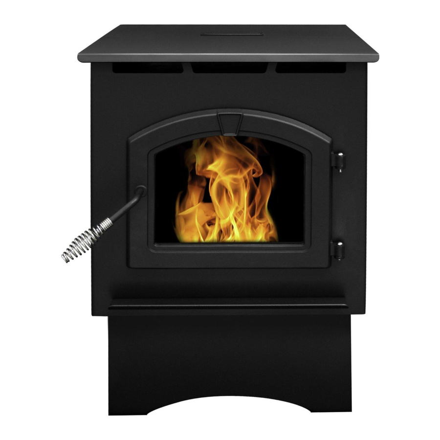
PH35PS
Models:
PH35PS Series - Medium Pellet Stove with Pedestal
PH50PS Series - Large Pellet Stove with Pedestal and Base Pan
PH50CABPS Series - Cabinet Pellet Stove
SAFETY NOTICE: PLEASE READ THIS ENTIRE MANUAL BEFORE INSTALLATION AND USE OF
THIS PELLET FUEL-BURNING ROOM HEATER. FAILURE TO FOLLOW THESE INSTRUCTIONS
COULD RESULT IN PROPERTY DAMAGE, BODILY INJURY OR EVEN DEATH. CONTACT LOCAL
BUILDING OFFICIALS ABOUT RESTRICTIONS AND INSTALLATION INSPECTION REQUIRE-
MENTS IN YOUR AREA.
Questions, problems, missing parts? Before returning to your retailer, call our
8280 Austin Avenue
Morton Grove, IL 60053
customer service department at 877-447-4768 8:30 a.m – 4:30 p.m. CST,
877-447-4768
High Efficiency Pellet Stove
Owner's Manual
Installation and Operation
SAVE THESE INSTRUCTIONS
This heater meets the U.S. Environmental
Protection Agency's emission limits for
wood heaters sold after July 1, 1990.
Monday – Friday or email us at customerservice@ghpgroup.com.
7077-171 • July 16, 2012
PH50PS
PH50CABPS
1
Advertisement
Table of Contents

Related Manuals for pleasant hearth PH35PS Series


Summary of Contents for pleasant hearth PH35PS Series
- Page 1 High Efficiency Pellet Stove PH35PS PH50PS PH50CABPS Models: PH35PS Series - Medium Pellet Stove with Pedestal PH50PS Series - Large Pellet Stove with Pedestal and Base Pan PH50CABPS Series - Cabinet Pellet Stove Owner’s Manual Installation and Operation SAFETY NOTICE: PLEASE READ THIS ENTIRE MANUAL BEFORE INSTALLATION AND USE OF THIS PELLET FUEL-BURNING ROOM HEATER.
- Page 2 CAUTION IMPORTANT It is highly recommended that the pellet heater After reading these instructions, if you have any doubt about your ability to complete your installation in a pro- and chimney be installed by a qualified installer. A fessional manner you should obtain the services of an qualified installer is a person or entity who regularly installer versed in all aspects as to the correct and safe installs solid burning fuel products and chimneys in...
-
Page 3: Listing And Code Approvals
• Install any component not approved by the GHP for replacement glass. manufacturer • Install parts or components not Listed or approved D. Electrical Rating (On High) • Disable safety switches PH35PS Series: 115 VAC, 60 Hz, Start 2.6 Amps, Improper installation, adjustment, alteration, service or Run 0.9 Amps maintenance can cause injury or property damage. PH50PS Series: 115 VAC, 60 Hz, Start 2.6 Amps, For assistance or additional information, consult a qualified Run 0.9 Amps... - Page 4 Hearth & Home Technologies Inc. HEATILATOR ECO-CHOICE WARRANTY User Guide: General Information A. Fire Safety Clinkers Hearth & Home Technologies Inc., on behalf of its hearth brands (“HHT”), extends the following warranty for ECO- To provide reasonable fire safety, the following should be CHOICE by heatilator wood and pellet hearth appliances that are purchased from an HHT authorized dealer.
- Page 5 User Guide: General Operating Information A. User Dial Control The appliance has one dial control located on the side of the unit used for daily operation. There are four primary settings on this dial. 1) Off : When the dial indicator is in the off position the unit will go into a shut down and remain off until the dial is turned to one of the other three settings.
- Page 6 User Guide: General Operating Information C. Priming the Feed Tube F. Starting Your First Fire If the hopper is being filled for the first time or the unit had 1) Turn the dial control to “OFF”. previously run out of pellets, the feed tube may need to 2) Make sure the firepot is clean, inplace, and free of be primed.
- Page 7 User Guide: General Operating Information WARNING HOT SURFACES! Glass and other surfaces are hot during operation AND cool down. Hot glass will cause burns. • DO NOT touch glass until it is cooled • NEVER allow children to touch glass •...
- Page 8 User Guide: General Operating Information I. LED Color Coding Chart and Explanation Number of Description Notes Color Flashes between pauses Green Steady ON Feed Motor is running continuously. When priming the feed system and filling (max time 2 min- (This primes the feed tube). the firepot, NO NOT OVERFILL FIREPOT utes) .
- Page 9 User Guide: General Operating Information J. Ignition Cycles M. Clear Space 1. At the beginning of each ignition cycle, it is normal to see WARNING! RISK OF FIRE! Do NOT place combustible some smoke in the firebox. The smoke will stop once objects in front or to the sides of the appliance. High tem- the fire starts.
- Page 10 Maintaining & Servicing Your Appliance C. General Maintenance A. Proper Shutdown Procedure 1. Types of Fuel CAUTION The type of fuel you are burning will dictate how often you have to clean your firepot. Shock and Smoke Hazard If the fuel you are burning has a high dirt or ash content, it may •...
- Page 11 Maintaining & Servicing Your Appliance 2. Cleaning Firepot with the Firepot Clean-Out Tool; 3. Ash Removal from Firebox • Frequency: Daily or more often as needed • Frequency: Weekly or more frequently depending on • By: Homeowner ash build-up. • By: Homeowner a.
- Page 12 Maintaining & Servicing Your Appliance 6. Cleaning the Glass 8. Cleaning the Exhaust Path, Baffles & Drop Tube • Frequency: Monthly or every 25 bags or more fre- • Frequency: When clear view of the firepot becomes quently depending on ash build-up. obscure •...
- Page 13 Maintaining & Servicing Your Appliance 10. Cleaning Convection Blower - Requires No Lubrication • Frequency: Monthly depending on Dust/Dirt build-up • By: Homeowner or Qualified Service Technician a. Be sure the appliance is allowed to cool and has been unplugged. b.
- Page 14 Maintaining & Servicing Your Appliance D. High Ash Fuel Content Maintenance • Frequency: As needed • By: Homeowner Poor quality pellet fuel, lack of maintenance, or if the small dial control is set to a less than optimum setting, poor com- bustion conditions that make the firepot fill quickly with ashes and clinkers.
- Page 15 Maintaining & Servicing Your Appliance E. Frequently Asked Questions What causes my glass to become dirty? Why is there a black residue building up on the If the glass has white ash build up it is normal and the outside of my home? glass should be cleaned.
-
Page 16: Replacement Parts
Replacement Parts A. Convection Blower Replacement B. Exhaust Blower Replacement 1. Turn the dial control to the off position. Unplug the power 1. Turn the dial control to the off position. Unplug the power to the unit. to the unit. 2. - Page 17 Replacement Parts D. Igniter Replacement . Snap Disc Replacement Power - Manual Reset 1. Turn the dial control to the off position. Unplug the power to the unit. 1. Turn the dial control to the off position. Unplug the power to the unit.
- Page 18 Replacement Parts F. Glass Replacement I. Feed Motor Replacement 1. Turn the dial control to the off position and unplug the WARNING unit. Remove the right side panel and feed motor cover plate in the rear of the unit. • Glass is 5mm thick high temperature heat- 2.
-
Page 19: Getting Started
Getting Started Installer’s Guide A. Design, Installation & Location Considerations B. Draft (Cont’d) NOTICE: Check building codes prior to installation. Correct low draft or low vacuum problems by doing one of the following: • Installation MUST comply with local, regional, state and • Thoroughly clean the exhaust path and venting. See national codes and regulations. -
Page 20: Getting Started
Getting Started Installer’s Guide D. Locating Your Appliance & Chimney F. Tools And Supplies Needed Location of the appliance and chimney will affect Tools and building supplies normally required performance. for installation, unless installing into an existing • Install through the warm airspace enclosed by the building masonry fireplace: envelope. -
Page 21: Dimensions And Clearances
Dimensions and Clearances MODEL: PH35PS MODEL: PH50PS A. Appliance Dimensions A. Appliance Dimensions 23-3/4 [603] 21-3/4 [552] 3-1/2 [102] [89] 24-5/16 21-15/16 [617] [558] [864] [762] 4-1/8 [104] 4-1/8 [105] 26-13/16 30-13/16 [681] [783] [305] [330] 19-7/8 [505] 24-3/8 [620] 7077-171 •... - Page 22 Dimensions and Clearances B. Clearances to Combustibles (UL and ULC) MODEL: PH50CAB A. Appliance Dimensions 23-3/4 [603] 4-1/2 [114] 23-3/16 [590] Vertical Installations Straight Back Against Wall Inches Millimeters Back Wall to Appliance Side Wall to Appliance Corner Installation Inches Millimeters Walls to Appliance Horizontal Installations...
- Page 23 Dimensions and Clearances C. Hearth Pad Requirements (UL and ULC) Use a non-combustible floor protector, extending beneath appliance and to the front, sides and rear as indicated. Measure front distance “M” from the surface of the glass door. Must extend 2 inches (51mm) beyond each side of pipe (shaded area) *C Exception for Horizontal Installations: USA Hearth Pad Requirements...
-
Page 24: Vent Information
Vent Information B. Venting Termination Requirements A. Chimney and Exhaust Connection CAUTION Chimney & Connector: Use 3 or 4 inch (76-102mm) Do not terminate vent in any enclosed or semi-enclosed diameter type "L" or "PL" venting system. It can be vented area such as a carport, garage, attic, crawl space, under a vertically or horizontally. - Page 25 Vent Information C. Pellet Venting Charts The maximum horizontal venting allowed with no vertical vent- WARNING ing attached is 48 inches (1219mm) including one 90° elbow or two 45° elbows. This is our recommended horizontal vent- Fire Risk. ing installation. Addition of any horizontal venting beyond 48 •...
-
Page 26: Venting Systems
Venting Systems B. Through The Wall & Vertical - External A. Vertical - Interior - Typical Installation PREFERRED METHOD #2 PREFERRED METHOD #1 Rain Cap Rain Cap 12 in. Flashing (305mm) 12 in. Minimum Flashing (305mm) Minimum Firestop 10 in. (254 mm) Minimum Support Bracket Every 60 in. - Page 27 Venting Systems WARNING WARNING Fire Risk Improper installation, adjustment, alteration, service or Inspection of Chimney: maintenance can cause injury or property damage. Refer to the owner’s information manual provided with this appli- • Masonry chimney must be in good condition. ance.
- Page 28 Venting Systems F. Through The Wall Horizontal termination cap must be a minimum of 6 inches. (152mm) from the wall. Approved for mobile home instal- In Canada, where passage through a wall or parti- lations. Must use 3 or 4 inch (76-102mm) “L” or “PL” listed tion of combustible construction is desired, the pellet venting or Listed double wall pipe and an authorized installation shall conform to CAN/CSA-B365...
-
Page 29: Mobile Home
Mobile Home A. Mobile Home Installation CAUTION You must use an authorized Outside Air Kit THE STRUCTURAL INTEGRITY OF THE MOBILE HOME for installation in a mobile home. FLOOR, WALL AND CEILING/ROOF MUST BE MAIN- TAINED An outside air inlet must be provided for the combustion Do NOT cut through: air and must remain clear of leaves, debris, ice and/or •... - Page 30 Appliance Set-Up A. Outside Air Kit Instructions CAUTION An outside air kit has been provide standard with the appli- Never draw outside combustion air from: ance. It is highly recommended to use the outside air kit for • Wall, floor or ceiling cavity maximum performance and to reduce effects from negative •...
-
Page 31: Troubleshooting
Troubleshooting Symptom Possible Cause Corrective Action Plug in appliance - No No Power to outlet. Check circuit breaker at service panel. response. 5 amp fuse defective or blown Replace fuse. Snap disc tripped or defective. Reset or replace snap disc. Unit Will Not Light No Fuel Out of fuel. - Page 32 Troubleshooting Symptom Possible Cause Corrective Action Slow or smoky start-up Dirty exhaust and/or venting system. Check for ash build up in unit, including behind rear and/or lazy flame panels, firebox, exhaust blower and venting. Not enough combustion air Adjust the trim Misaligned igniter Center the igniter in the chamber Wet fuel / poor quality fuel...
- Page 33 Troubleshooting Following correction of any Alarm, turn the dial control to the OFF position, wait 10 seconds and turn back to desired setting OR unplug the unit, wait 10 seconds then restore power. Alarm Possible Cause Corrective Action (LED Flashing RED) 1 Flash: Empty Hopper No fuel is delivered to the firepot to sustain flame Fill the hopper, inspect the feed tube for jams, inspect Hopper empty (most likely)
-
Page 34: Reference Materials
Reference Materials A. Component Function When describing the location of a component, it is always AS YOU FACE THE FRONT OF THE 1. Control Board APPLIANCE. The control board is located on the right side of the appliance behind the lower right side panel. Snap Disc (Back Burn Protector) 200°F 2. - Page 35 Reference Materials B. Wiring Diagram IGNITER VACUUM HOPPER FEED MOTOR SWITCH SWITCH EXHAUST BLOWER CONVECTION BLOWER NEUTRAL 110 V LINE SNAP DISC FUSE EXHAUST TEMPERATURE AMBIENT TEMPERATURE SERIAL PORT (SERVICE ONLY) POT SET TEMP VCC POT SET TEMP GND POT SET TEMP SIG POT FEED ADJUST VCC POT FEED ADJUST GND POT FEED ADJUTS SIG...
- Page 36 Reference Materials 10 12 12.7 12.6 12.5 12.4 12.3 12.2 12.1 Replacement Parts 1. Hopper Lid (1 per unit)* 12. Feed Assembly 2. Side Panels (2 per unit)* 12.1 Bronze Bushings (2 per unit) 3. Front Door Assembly 12.2 Auger Assembly 3.1 Spring handle and hinge pins 12.3 Feed Motor Hitch Pin...
-
Page 37: Service And Maintenance Log
Service And Maintenance Log Date of Service Performed By Description of Service 7077-171 • July 16, 2012... - Page 38 Homeowner Notes 7077-171 • July 16, 2012...
- Page 39 Do not attempt to do any service work yourself, unless pre-ap- respect to the sale of this GHP Group product. proved by GHP Group in writing as this will void the warranty. 9. The warranties as outlined within this document do not apply to...
- Page 40 8280 Austin Avenue Morton Grove, IL 60053 877-447-4768 Please contact the GHP Group with any questions or concerns. www.ghpgroupinc.com For Customer Service 1-877-447-4768 Prior to calling, please have the model, serial number, and sales receipt of the unit you are calling about.
Need help?
Do you have a question about the PH35PS Series and is the answer not in the manual?
Questions and answers