Advertisement
CITY MULTI Control System
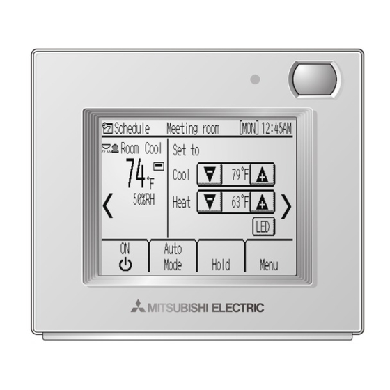
Smart ME Controller
Installation Manual
Chapter 1. Installation
This installation manual describes how to install the Smart ME Controller for use with Mitsubishi
Building Air Conditioning System, direct expansion type CITY MULTI air conditioner indoor units ("-A"
type and later).
Please be sure to read this installation manual and Instruction Book that are supplied with the Remote
Controller before proceeding with the installation. Failure to follow the instructions may result in
equipment damage.
For information on how to wire and install the air conditioning units, refer to the Air Conditioner
Installation Manual.
After the installation, hand over this manual to users.
Smart ME Controller is a type of ME Remote Controllers, sometimes simply referred to as ME Remote
Controller.
1
Safety Precautions
• Read the following safety precautions prior to installation.
• Observe these precautions carefully to ensure safety.
WARNING
CAUTION
• After reading this manual, pass it on to the end user to retain for future reference.
• Keep this manual for future reference and refer to it as necessary. This manual should be made
available to those who repair or relocate the controller. Make sure that the manual is passed on to
any future users.
All electric work must be performed by qualified personnel.
General precautions
WARNING
Do not install the unit in a place where large amounts of
oil, steam, organic solvents, or corrosive gases, such
as sulfuric gas, are present or where acidic/alkaline
solutions or sprays are used frequently. These
substances can compromise the performance of the
unit or cause certain components of the unit to corrode,
which can result in electric shock, malfunctions,
smoke, or fire.
To reduce the risk of shorting, current leakage, electric
shock, malfunctions, smoke, or fire, do not wash the
controller with water or any other liquid.
To reduce the risk of electric shock, malfunctions,
smoke or fire, do not operate the switches or touch
other electrical parts with wet hands.
PAR-U01MEDU
Indicates a risk of death or serious injury.
Indicates a risk of serious injury or structural damage.
For distribution to dealers and contractors
To reduce the risk of injury or electric shock, before
spraying a chemical around the controller, stop the
operation and cover the controller.
To reduce the risk of injury or electric shock, stop the
operation and switch off the power supply before
cleaning, maintaining, or inspecting the controller.
Properly install all required covers to keep moisture
and dust out of the controller. Dust accumulation and
water can cause electric shock, smoke, or fire.
To reduce the risk of injury, keep children away while
installing, inspecting, or repairing the controller.
– 1 –
WT06684X01
GB
Advertisement
Table of Contents

Related Manuals for Mitsubishi Electric Smart ME Controller


Summary of Contents for Mitsubishi Electric Smart ME Controller
-
Page 1: Chapter 1. Installation
For information on how to wire and install the air conditioning units, refer to the Air Conditioner Installation Manual. After the installation, hand over this manual to users. Smart ME Controller is a type of ME Remote Controllers, sometimes simply referred to as ME Remote Controller. Safety Precautions •... -
Page 2: Precautions During Installation
CAUTION To reduce the risk of fire or explosion, do not place To avoid injury from broken glass, do not apply flammable materials or use flammable sprays around excessive force on the glass parts. the controller. To reduce the risk of injury, wear protective gear when To reduce the risk of damage to the controller, do not working on the controller. -
Page 3: Additional Precautions
This controller is designed for exclusive use with the mild detergent, wipe off the detergent with a wet cloth, Building Management System by Mitsubishi Electric. and wipe off water with a dry cloth. The use of this controller for with other systems or for other purposes may cause malfunctions. - Page 4 Component names and supplied parts The following parts are included in the box. Parts name Qty. Remote controller (front cover) *1 Remote controller (top case) *1 Remote controller (bottom case) Front cover Top case Bottom case Roundhead cross slot screws M4×30 *2 Wood screw 4.1×16 *2 (for direct wall installation) Installation Manual (this manual)
-
Page 5: System Diagram
*1 The power consumption coefticient of the Smart ME Controller is “0.5” and that of a ME Remote Controller (PAR-F27MEA-US) is “0.25”. If the number of Smart ME controllers is high and the total power supply they require exceeds the outdoor unit's ability to supply power, a Transmission booster (PAC-SF46EPA) will be required. -
Page 6: How To Install
How To Install This remote controller is for the wall installation. It can be installed either in the switch box or directly on the wall. When performing direct wall installation, cables can be thread through either back or top of the remote controller. (1) Selecting an installation site Install the remote controller (switch box) on the site where the following conditions are met. -
Page 7: Handling Precautions
Occupancy sensor detects occupancy based on the temperature difference between the occupant and its surroundings. To be precise, to enhance the sensitivity of the sensor to occupant movements, the occupancy sensor is designed to detect the changes in the amount of infrared light emitted from an object in the detection zone, including human bodies. - Page 8 (2) Installation space Leave a space around the remote controller as shown in the figure below, regardless of whether the controller is installed in the switch box or directly on the wall. Removing the remote controller will not be easy with insufficient space. Also, leave an operating space in front of the remote controller.
- Page 9 • Cut out the thin-wall part on the cover (indicated with the shaded area in the right figure) with a knife or a nipper. Note: Make sure that the hole edges are smooth and will not damage the wires. 4 Install the bottom case. •...
- Page 10 6 Connect the remote controller cable to the terminal block on the top case. Connect the remote controller cable to the terminal block. Connect the cable to the terminal block, and insert the cable into the groove. To reduce the risk of electric shock, shorting, or malfunctions, keep wire pieces and sheath shavings out of the terminal block.
- Page 11 7 Set the M-NET addresses. Rotary switches 10's digit (Above) 1's digit (Below) (Ex: Address 108) Address range Address setting method Address that equals the lowest address of the Main remote controller 101 to 150 group plus 100 Address that equals the lowest address of the Sub remote controller 151 to 200 group plus 150...
- Page 12 ■ Direct wall installation (when running the cable along the wall) Putty • Thread the cable through the access hole at the top of the remote controller. • Seal the cut-out part of the cover with putty. • Use a cable cover. Installation is complete.
- Page 13 Important ■ Discrepancy between the room temperature measured at the wall and the actual room temperature may occur. If the following conditions are met, the use of the temperature sensor on the indoor unit is recommended. • Air distribution in the space is poor. •...
-
Page 14: Chapter 2. Initial Setting
Chapter 2. Initial Setting This chapter contains information about the settings to be made at the time of installation. Please read the instructions carefully and make the settings accordingly. Refer to Chapter 1 “Installation” for how to install the Remote Controller, and refer to the air conditioning unit installation manuals for how to connect the controller cable to the air conditioning units, or how to install the air conditioning units. - Page 15 (2) Setup screen (a) Group setting Use this screen to register the indoor units and the AHC to be controlled from the controller. 1 Select an indoor unit or an AHC address in the [Address] field. The number of units that can be registered. Indoor unit: 16 units maximum AHC: 1 unit maximum * AHC cannot be controlled from the controller unless indoor...
-
Page 16: Service Menu
Service Menu [HOME screen] [MENU(User) screen] [MENU(Service) screen] A password is required to access the Menu Service screen or some settings under the Menu User screen • The initial Service password is “9999.” The initial User password is “0000.” Change the password as necessary to prevent unauthorized access. - Page 17 Item Detail Description Setting Default (1) Setup (i) Room name Use to enter room names (max. Use a combination of Blank 16 characters). The names capital letters, small- entered here will appear on the case letters, numerical HOME screen. characters and symbols. Telephone Use to enter the telephone Use numerical...
- Page 18 (1) Setup menu (a) Group setting Refer to section 1 "Initial Settings" (2) "Setup screen". (b) LOSSNAY interlock Refer to section 1 "Initial Settings" (2) "Setup screen". (c) Search connection inf. Refer to section 1 "Initial Settings" (2) "Setup screen". (d) Cool/Heat display (e) Override time (f) Temperature sensor offset...
- Page 19 (j) Telephone number (k) IC function setting (max. 13 numbers) 1Select the indoor unit address in the [M-NET address] field. (When [Grp] has been selected, all the indoor units that are controlled from the controller will be selected.) 2Select the desired function number in the [Function number] field.
- Page 20 (m) Reset RC (n) AHC port name (max. 20 characters) (2) Error Menu (a) Error history (b) Self check (max. 16) – 20 –...
- Page 21 (3) Test Run [Indoor unit setting screen] [Test run screen] (a) Read the section about Test run in the indoor unit Installation Manual before performing a test run. (b) During the test run, indoor units will be forced to operate in the Thermo-ON status. Except the set temperature, normal operation functions are accessible during test run.
- Page 22 Receives power from outdoor units via the M-NET 17-32 VDC *1 Power Source transmission cable. The power consumption (for connection to M-NET only) coefficient* of the Smart ME Controller is “0.5”. Operating temperature range 0ºC – +40ºC (+32ºF – +104ºF) Temperature Operating conditions Storage temperature range -20ºC –...
- Page 23 – 23 –...
- Page 24 This product is designed and intended for use in the residential, commercial and light-industrial environment. The product at hand is based on the following EU regulations: • Electromagnetic Compatibility Directive 2004/108/EC • Restriction of Hazardous Substances 2011/65/EU Please be sure to put the contact address/telephone number on this manual before handing it to the customer.
Need help?
Do you have a question about the Smart ME Controller and is the answer not in the manual?
Questions and answers