Table of Contents
Advertisement
Advertisement
Table of Contents

Subscribe to Our Youtube Channel
Related Manuals for Shibaura ST460


Summary of Contents for Shibaura ST460
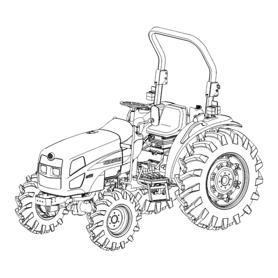
- Page 1 OPERATOR'S MANUAL MODEL ST460...
-
Page 2: To The Owner
This manual contains information concerning the adjustment and maintenance of your SHIBAURA Model ST460. You have purchased a dependable machine, but only by proper care and operation can you expect to receive the performance and long service built into this tractor. Please have all operators read this manual carefully and keep it available for ready reference. -
Page 3: Table Of Contents
CONTENTS GENERAL INFORMATION AND SAFTY ············································································· 1-1 CONTROLS, INSTRUMENTS AND OPERATION ································································ 2-1 LUBRICATION AND MAINTENANCE ·················································································· 3-1 SPECIFICATIONS ················································································································ 4-1 INDEX·································································································································· 4-12 PRE-DELIVERY SERVICE ································································································· 4-15 PRE-DELIVERY CHECKLIST ····························································································· 4-17 0- 2... -
Page 4: General Information And Safty
All data given in this manual is subject to production variations. Dimensions and weights are approximate only and the illustrations do not necessarily show tractors in standard condition. For exact information about any particular tractor please consult your SHIBAURA Tractor Dealer. - Page 5 Ensure that each piece of non-SHIBAURA When using a high pressure washer, do not equipment fitted to the tractor bears the CE stand too close to the tractor and avoid directing mark.
- Page 6 METRIC BOLT TORQUE SPECIFICATION Coarse Thread Fine Thread Bolt Size Grade No. Pitch (mm) Pounds-Feet Newton Meters Pitch (mm) Pounds-Feet Newton-Meters 3.6 – 5.1 4.9 – 6.9 6.1 – 8.3 8.3 – 11.3 – – – 8.7 – 11.6 11.8 – 15.7 9.4 –...
- Page 7 PRECAUTIONARY STATEMENTS PERSONAL SAFETY Throughout this manual and on machine decals, you will find precautionary statements (“CAUTION”, ”WARNING”, and “DANGER”) followed by specific instructions. These specifications are intended for the personal safety of you and those working with you. Please take the time to read them. CAUTION The word “...
-
Page 8: Safety Precautions
Do not exceed the result in death or injury. If your tractor is not legal speed limit set in your country for equipped with a roll bar, see your SHIBAURA agricultural tractors. Dealer. 3. Dip the tractor lights when meeting a vehicle 4. - Page 9 3. Do not bypass the neutral start switches. 14. Ensure attached equipment Consult your SHIBAURA dealer if your accessories correctly installed, neutral start controls malfunction. approved for use with the tractor, do not overload the tractor and are operated and 4.
- Page 10 15. Remember that your tractor, if abused or 5. Ensure the PTO master shield is installed at incorrectly used, can be dangerous and all times. Always replace the PTO shield cap become a hazard both to the operator and to when the PTO is not in use.
- Page 11 This equates but not components carried out by an authorized limited to protection of eyes, lungs, ears, head, SHIBAURA Dealer. If, however, service hands and feet when operating, servicing or operations are to be undertaken on parts that repairing the equipment.
- Page 12 PREVENTION OF FIRE OR EXPLOSION 1. Due to the flammable nature of some crop 8. If a fire extinguisher has been used, always materials, the risk of tractor fire can be high. recharge or replace the extinguisher before This risk can be minimised by frequent operating the tractor in conditions where a fire may occur.
- Page 13 DIESEL FUEL SAFETY FRAME (ROPS) 1. Under no circumstances should gasoline, Your SHIBAURA Tractor is equipped with a alcohol, or blended fuels be added to diesel safety frame. It must be maintained in a fuel. These combinations can create an serviceable condition.
-
Page 14: Ecology And The Environment
ECOLOGY AND THE ENVIRONMENT HELPFUL HINTS Soil air, and water are vital factors of agriculture 1. Avoid filling tanks using cans or inappropriate and life in general. When legislation does not yet pressurized fuel delivery systems, which may rule the treatment of some of the substances, cause considerable spillage. - Page 15 Manual and walk around your tractor, noting the location of the decals and their significance. Review the decals and operating instructions detailed in this Manual with the machine operators. Keep the decals clean and legible. If they become damaged or illegible, obtain replacements from your SHIBAURA dealer. DECAL PLACEMENT GUIDE 1-12...
- Page 16 1. Location: • Left hand side fender. • Inside of hood. WARNING: Read and understand all the warning notes printed in the Operator’s Manual. In particular, read the General Information and Safety section in the Operator’s Manual. Part No. 390197900 2.
- Page 17 5. Location: Front of battery stand. DANGER: Explosive gas. Avoid any open fires. Corrosive acid. Wear eye protection. Part No. 390199450 6. Location: Battery. CAUTION: Comply with legal regulations and guidelines for disposal of battery. Part No. 390199430 7. Location: Starter Motor. WARNIMG: Do not start the engine by shorting across the starter terminals.
- Page 18 9. Location: Beside of fuel filler cap. DANGER: Keep any type of open flame away. Cause an explosion and fire. Diesel fuel only. Part No. 490992430 10. Location: Left hand side fender. WARNIMG: Read the Operator’s Manual before attempting to tow the tractor. Part No.
- Page 19 13. Location: Left hand side ROPS. WARNIMG: Always turn the key to OFF position and remove it, before performing any intervention or service on the tractor; always refer to the Operator’s manual for specific information. WARNIMG: Always wear the seat belt when the tractor is equipped with a ROPS with raised locking position.
- Page 20 16. Location: Right hand side ROPS. WARNIMG: To avoid injury, do not stand on the implement or between the implement and tractor while operating the HPL lift or PTO controls. Always operate the HPL lift or PTO controls from operator seat. Part No.
- Page 21 INSTRUCTION DECALS Front-Wheel Creep shift Lever PTO speed shift Lever Drive Control Lever PART NO: 390170680 PART NO: 390171170 PART NO: 390173871 LOCATION: Lower LOCATION: Left Side LOCATION: Lower Left Side of Operator’s Control Panel Left Side of Operator’s Platform Platform PTO Mode Selector Switch...
- Page 22 Forward/Reverse 4-Speed Turn Signal Shuttle Lever Transmission Lever PART NO: 390380960 PART NO: 390174131 PART NO: 390174140 LOCATION: Left Side LOCATION: Left Side LOCATION: Right Side of Dash of Dash of Dash Road Light Switch Road Light High Horn Switch PART NO: 390380791 Beam Switch PART NO: 390230970...
- Page 23 Differential Lock Starter Switch Flow Control Valve PART NO: 390198301 PART NO: 390197280 PART NO: 390372471 LOCATION: Above LOCATION: Starter LOCATION: Top of Pedal Right Side of Switch, Right Side of Flow Control Knob Operator’s Platform Instrument Panel Engine Oil Power Steering Fluid Rear Remote Control PART NO: 390230220...
-
Page 24: Universal Symbols
UNIVERSAL SYMBOLS As a guide to the operation of your tractor, various universal symbols have been utilized on the instruments, controls, switches, and fuse box. The symbols are shown below with an indication of their meaning. 1-21... -
Page 25: Airborne Noise Emission
Model Transmission Closed – Open – Drive by Stationary dB(A) dB(A) dB(A) dB(A) ST460 4WD EHSS 88.7 79.0 80.0 ST460 4WD 87.0 80.0 80.0 * Test results are in accordance with directive 2009/76/EC Annex II. ** Test results are in accordance with directive 2009/63/EC Annex VI. -
Page 26: Controls, Instruments And Operation
CONTROLS, INSTRUMENTS AND OPERATION SEAT AND MIRROR Adjusting the Tractor Seat Your SHIBAURA tractor equipped with an adjustable suspension seat. To adjust the seat fore and aft, move the release lever ① towards the fender, slide the seat to the desired position, releasing the lever to lock. - Page 27 It is recommended that you equip your tractor with a ROPS. ROPS are effective in reducing injuries during tractor overturn accidents. Overturning tractor without a ROPS can result in serious injury or death. Roll Over Protective Structure (ROPS), is available from your SHIBAURA Tractor Dealer.
- Page 28 SECTION 2 – OPERATION WARNING When improperly operated, a tractor can roll over. For low clearance use only, the ROPS may be lowered. No protection is provided when the tractor is operated with the ROPS in the lowered position. ALWAYS raise ROPS lock...
- Page 29 SECTION 2 – OPERATION INSTRUMENT PANEL 1. Cold Starting Indicator Light 3. Battery Charge Warning Light Illuminate when the key switch is turned to the Illuminates when the key switch is in the "ON" or "HEAT" position. It remains lit for approximately 5 "HEAT"...
- Page 30 SECTION 2 – OPERATION 5. Fuel Gauge 10. Rear PTO Speed Indicates the amount of diesel fuel remaining in Determined by the position of the needle on the the tank. The gauge is activated when the key tachometer. The tachometer is marked to switch is in the "ON"...
- Page 31 SECTION 2 – OPERATION KEY SWITCH The key switch ① is located on the right-hand side of the console, just below the hand throttle. Turning the key clockwise, to the "ON" position, activates the warning lights and instruments. The pre-heat system is activated when the key is turned farther clockwise to the "HEAT"...
- Page 32 SECTION 2 – OPERATION STARTING THE ENGINE The key switch ① allows activation of the starter motor and fuel delivery only when: The PTO control switch ③ is in the “OFF” position. Forward/Reverse shuttle lever ② is in the “NEUTRAL” position. ④...
- Page 33 BREAK-IN PROCEDURES 3. Set the PTO control switch is in the “OFF” Your SHIBAURA tractor will provide long and position. dependable service if given proper care during 4. Connect one end of the jumper cable to the the first 50-hour break-in period.
- Page 34 SECTION 2 – OPERATION LIGHTING Your tractor equipped with: • Headlights ① Side and Taillights / Brake Lights ② • • Flasher Warning Lights / Turn Signals ③...
- Page 35 SECTION 2 – OPERATION Headlights and Taillights There are headlights located in the front of the tractor hood, dual element road lights ①. The key switch must be in the “ON” position for the lights to operate. Light Switches Road Lights Switch ③ Rear Position “OFF”.
- Page 36 SECTION 2 – OPERATION Flasher Warning (Hazard) Lights The flasher warning lights ① are activated by placing rocker switch ② in the front position. The flasher warning lights can be activated with the key switch in any position. For your protection, use the flasher warning lights when traveling on public roads, day or night.
- Page 37 SECTION 2 – OPERATION Brake Lights The brake lights ① are activated when the brake pedals are depressed, with the key switch in any position. The brake lights illuminating, warns anyone following the tractor, the brakes are being applied and the tractor ground speed is being reduced.
- Page 38 SECTION 2 – OPERATION THROTTLE CONTROLS The hand throttle ① is located on the RH side of the console. Push the throttle forward to increase the engine RPM, Pull the throttle rearward to decrease the RPM. The foot throttle ② is located on the right-hand foot platform and can be used separately, or in conjunction with the hand throttle.
- Page 39 SECTION 2 – OPERATION BRAKE CONTROLS Brake Pedals The right brake pedal controls the braking action of the right rear wheel. The left brake pedal controls the left rear wheel brake. Depress both pedals ① simultaneously to stop the tractor. To assist in making sharp turns at slow speed, depress the right or left brake pedal as required.
- Page 40 SECTION 2 – OPERATION TRANSMISSION, FRONT-WHEEL DRIVE AND P.T.O FRONT-WHEEL DRIVE The front-wheel drive is controlled by a lever ① located on the left lower side of operator’s platform. To engage front-wheel drive, move the lever completely upwards. To disengage front-wheel drive, move the lever fully downward.
- Page 41 SECTION 2 – OPERATION EHSS OR SSS 24 x 24 TRANSMISSION The 24 x 24 shuttle transmission operates through the use of a inching pedal (EHSS) or clutch pedal (SSS) ① a forward / reverse shuttle lever ② a main shift lever ③ and a range speed selector lever ④...
- Page 42 SECTION 2 – OPERATION TRANSMISSION SHUTTLE LEVER (FORWARD OR REVERSE) EHSS The shuttle shift lever ② is used to engage the transmission into the forward or reverse mode. Move the lever first upwards, then frontward for forward and rearward for reverse travel. The inching pedal does not need to be depressed while changing direction of travel with shuttle lever.
- Page 43 SECTION 2 – OPERATION TRANSMISSION MAIN SHIFT LEVER (1st, 2nd, 3rd, 4th) The transmission main shift lever ③ is located on the right-hand side of the dash console. A decal of the shift pattern is located on the console. Each of the three ranges and creep gear has four forward gears and four reverse gears, providing a total of twenty-four forward and twenty-four reverse speeds.
- Page 44 SECTION 2 – OPERATION INCHING PEDAL (EHSS) The foot operated inching pedal ① must be completely depressed to stop forward or reverse travel. Always depress the inching pedal fully when changing main shift, and range gears, also when engaging the creep gear, and front wheel drive.
- Page 45 SECTION 2 – OPERATION DIFFERENTIAL CONTROL The differential lock pedal ① is located on the right-hand foot platform. The differential lock is used to obtain additional traction in wet or loose soil. When differential lock pedal depressed, both final drive pinion gear shafts are locked together, preventing one wheel from rotating independently of the other.
- Page 46 SECTION 2 – OPERATION POWER TAKE-OFF (PTO) The power take-off (PTO) on your tractor transfers engine power directly to mounted or trailed equipment. All models operate through the standard 1 3/8 in. (34.9mm) diameter, 6-spline output shaft rotating at 540rpm, the speed at which most PTO driven equipment is designed to operate.
- Page 47 SECTION 2 – OPERATION PTO SPEED SHIFT LEVER The PTO speed shift lever ① is located by the left-hand fender. It has two PTO speed positions. Always turn “OFF” position the PTO control switch and bring the PTO drive to a complete stop before moving the PTO speed shift lever.
- Page 48 SECTION 2 – OPERATION POWER TAKE-OFF (PTO) OPERATION PTO speeds relative to engine speeds are shown in the following tables: WARNING Speed selector PTO Speed Engine To reduce the possibility of personal injury, position (rpm) speed (rpm) comply with the following guidelines before 2475 attaching or detaching PTO equipment, and before...
- Page 49 SECTION 2 – OPERATION EXTENSION / CLEVIS DRAWBAR Your tractor is equipped with a extension / clevis type drawbar for towing equipment behind the tractor. This drawbar may be extended for sliding it rearward, 145 mm. IMPORTANT: When transporting equipment on highways, a safety chain with a tensile strength equal to the gross weight of the implement should always be installed between the tractor...
- Page 50 SECTION 2 – OPERATION HOOD LATCH As viewed from the front of tractor: 1. To raise the hood, insert the thin stick such as screwdriver, in the hole that located under the front of right side of hood and push up the latch release rod ①, and lift the hood to its fully raised position.
- Page 51 SECTION 2 – OPERATION DELUXE THREE-POINT LINKAGE The three-point linkage has easy to adjust sway bars ① to control lateral movement of the lift The tractor’s three-point linkage is used to attach arms. The height of the right-hand lift arm and three-point mounted equipment which is usually the top link can be adjusted by turning the PTO operated, such as rotary mowers, tillers, flail...
- Page 52 SECTION 2 – OPERATION TOOL BOX A tool box ① with a magnetically latched lid, is located behind the seat and between the ROPS uprights. The tool box also incorporates a hanger bracket ② to support the top link of the three-point hitch, when not attached to an implement DRINK HOLDER...
- Page 53 TRACTOR HYDRAULICS HYDRAULIC POWER LIFT (H.P.L.) (3 PT) The HPL lever ① is located on the right-hand control pod. The lever controls the position of the two lift arms. To lower the lift arms, first make sure the drop rate control valve ③ is open, then move the HPL lever forward.
- Page 54 SECTION 2 – OPERATION DRATFT CONTROL When operating in draft control, the draft control lever ② used to adjust sensitivity to draft loads. Once the lever is positioned, the hydraulic lift system will automatically adjust the depth of the equipment to maintain an even load on the tractor as soil conditions vary.
- Page 55 SECTION 2 – OPERATION TWO LEVER CONTROLS POSITION CONTROL OPERATION Position control is obtained by placing the draft control lever ② all the way forward and then moving the outer (Position) control lever ① to position the equipment as desired. The outer (Position) lever is used to set the desired working height or depth.
- Page 56 SECTION 2 – OPERATION POSITION CONTROL ADJUSTMENT Linkage Adjustments The length of the position control rod is critical and careful adjustment must be observed for proper operation. If the control rod is adjusted too short, the control valve spool will remain in the raised position when the lift arms have reached their maximum height and the system relief valve will open to relieve hydraulic pressure.
- Page 57 SECTION 2 – OPERATION DRAFT CONTROL ADJUSTMENT NOTE: Adjust the draft rod only after completing the position control adjustment. 1. Set the draft control lever to the most sensitive “+” position of rearward. 2. Loosen the locknut ① on the draft control rod, ②.
- Page 58 SECTION 2 – OPERATION HYDRAULIC LIFT ROCKER The hydraulic lift rocker has two holes for attaching the upper link. Attach the link using the lower hole ① for light draft loads, such as mowers. Attach the link to the top hole ② for heavier draft loads, such as ground engaging equipment.
- Page 59 SECTION 2 – OPERATION HYDRAULIC MANIFOLD BLOCK/DIVERTER VALVE The hydraulic manifold block/diverter valve is located on the right-hand side of the tractor below platform. manifold block distributes pump oil to the HPL valve, optional rear remote valves, the transmission / rear axle reservoir and the valve for attached implement.
- Page 60 SECTION 2 – OPERATION REAR REMOTE CONTROL VALVE(S) (OPTIONAL) Your tractor can be equipped with one, two or three rear remote valves. The control lever(s) are located on the right-hand control pod, #1 remote ①, #2 remote ②, #3 remote ③. To operate the single-spool valve, pull the control lever rearward to extend the cylinder.
- Page 61 If necessary, readjust to eliminate tight or loose applications of the tractor brakes when chain. Safety chains and suitable hardware are pulling heavy towed loads at road speeds. available from your SHIBAURA Tractor Dealer Always sit in the driver's seat while starting or driving the tractor. 2-36...
- Page 62 SECTION 2 – OPERATION WHEEL TREAD SETTINGS NOTE: Tread settings are measured from center of tire to center of tire. Front Wheel Settings Tire Type Setting Note (AG) 8 - 16 1335 mm Not Adjustable (AG) 9.5 - 16 1442 mm Not Adjustable (TURF) 27 x 10.5 - 15 1462 mm...
- Page 63 SECTION 2 – OPERATION Position Rear FWD Tire Dimensions, mm Tire Type Inside To Inside Tread Setting Outside To Outside 1240 1575 1003 1338 1673 1109 1444 1779 1207 1542 1877 (AG) 13.6 - 28 1305 1640 1975 1403 1738 2073 1509 1844...
- Page 64 TRACTOR WEIGHTING When a mounted implement is raised to the transport position, the front wheel reaction For sufficient traction and maximum performance should be at least 20% of tractor weight. in heavy draft operations, and to counterbalance rear-mounted equipment, weight should be Add additional front end ballast as required for added to tractor in the form of liquid ballast, cast stability during operation and transport.
- Page 65 SECTION 2 – OPERATION CAST IRON WEIGHTS (OPTIONAL) Cast iron weights are available as accessories from your SHIBAURA Dealer. Weights can be mounted on the front end of the tractor and on the rearmost wheels. Front End Weights Tire Type...
- Page 66 Because special equipment is tractor or damage to the tractor may occur. required to fill the tires, consult your SHIBAURA Dealer. The chart below outlines tire inflation pressures. FRONT TIRE INFLATION PRESSURES...
- Page 67 SECTION 2 – OPERATION 2-42...
-
Page 68: Lubrication And Maintenance
See your SHIBAURA dealer for additional oil quantities. CAUTION Some illustrations in this manual show GENERAL INFORMATION shields opened or removed to show areas being serviced. Replace all shields before Regular lubrication is the best insurance against operating this machine. - Page 69 SECTION 3 – LUBRICATION AND MAINTENANCE LUBRICATION AND MAINTENANCE CHART SHIBAURA ST460 – FRONT-WHEEL DRIVE LUBRICATION & SERVICE LUBRICATION & SERVICE MAINTENANCE ITEMS INTERVALS MAINTENANCE ITEMS INTERVALS Engine Oil Level × Every Brake Pedal Free play × Every Air Cleaner ×...
- Page 70 • If the original fuel tank cap is lost, always 3. Wipe away any excess grease. replace it with a SHIBAURA approved cap. A "will-fit" cap may not be safe. DIESEL FUEL • Keep equipment properly maintained.
- Page 71 The tractor fuel tank capacity is 54 L. NOTE: The fuel cap is a vented-type. Use only an approved SHIBAURA replacement cap to prevent fuel system-related problems. If there is no filter on the storage tank or fuel container, filter the fuel through a 100-mesh or finer screen when filling the tractor fuel tank.
- Page 72 SAE 40 (CD) or SAE 50 (CD) in extremely high temperatures. IMPORTANT: Engine crankcase drain intervals should be adjusted downward when diesel fuel sulfur content is over 0.5%. Consult your SHIBAURA dealer for details of Engine Crank case Oil usage.
- Page 73 SECTION 3 – LUBRICATION AND MAINTENANCE FUEL AND LUBRICANT SERVICE PROCEDURES ENGINE Checking the engine oil level NOTE: Check the engine oil level daily, or after every 10 hours of operation. 1. After the engine has been stopped for a period of time, and with the tractor standing level, check the oil level using the dipstick ①.
- Page 74 SECTION 3 – LUBRICATION AND MAINTENANCE 2. Next, Place a suitable container below the oil filter ① to catch the used oil and unscrew the oil filter. Discard the used oil and filter. 3. Coat the gasket on the new filter with a thin film of new oil.
- Page 75 SECTION 3 – LUBRICATION AND MAINTENANCE FUEL FILTER Draining the Fuel Filter NOTE: The fuel filter should be drained after every 100 hours of operation. 1. Make sure there is adequate fuel in the fuel ① tank and close the fuel shutoff valve (the handle should be pointing to the "OFF"...
- Page 76 SECTION 3 – LUBRICATION AND MAINTENANCE Bleeding Air From the Fuel System The vehicle has an auto-bleed system, which should exhaust all air if the engine is cranking. The system should bleed with minimal cranking if the sediment bowl is filled with fuel. If the bowl is slow in filling, there is likely a blockage in the return vent lines.
- Page 77 SECTION 3 – LUBRICATION AND MAINTENANCE To bleed the fuel system: 1. Make sure there is adequate fuel in the fuel tank. 2. Open the fuel shutoff valve ①. 3. Remove hose ②, from the top of the bleed fitting. Reinstall hose when air-free fuel starts to flow.
- Page 78 SECTION 3 – LUBRICATION AND MAINTENANCE AIR CLEANER The air cleaner ① is accessed by opening the tractor hood. The air cleaner assembly contains two elements: an outer (primary) element, and an inner (safety) element. To remove the primary element, release the clips ②...
- Page 79 SECTION 3 – LUBRICATION AND MAINTENANCE Air Cleaner Primary Element NOTE: Clean the primary element after every 100 hours of service. Extremely dusty conditions may require more frequent service intervals. 1. Pull the primary element ③ from the canister. Clean any loose dirt from the canister and inspect the end of the canister for dirt, which may prevent the new element from sealing properly.
- Page 80 SECTION 3 – LUBRICATION AND MAINTENANCE Air Cleaner Inner Safety Element NOTE: For maximum engine protection and air cleaner service life, install a new inner safety element every third primary element change or after every 1000 hours of operation, whichever comes first.
- Page 81 SECTION 3 – LUBRICATION AND MAINTENANCE TRANSMISSION, REAR AXLE, AND HYDRAULIC SYSTEM Checking the Transmission, Rear Axle, and Hydraulic System Oil Level NOTE: Check the transmission, rear axle, and hydraulic system oil level after every 50 hours of operation. 1. With the engine off and the tractor standing level, check the oil level using the dipstick ①.
- Page 82 SECTION 3 – LUBRICATION AND MAINTENANCE Changing the Transmission, Rear Axle, and Hydraulic System Oil NOTE: Change the transmission, rear axle, and hydraulic system oil after every 300 hours of operation. NOTE: During cold weather operation, tractor hydraulic oil can be changed to ISO VG 46 oil is a multiviscosity oil which has improved flow characteristics in low temperatures and can be used year round.
- Page 83 SECTION 3 – LUBRICATION AND MAINTENANCE POWER STEERING Checking the Power Steering Oil Level NOTE: Check the power steering oil level after every 50 hours of operation. 1. With the tractor standing level and the engine off, check the oil level using the dipstick ①. 2.
- Page 84 SECTION 3 – LUBRICATION AND MAINTENANCE GENERAL MAINTENANCE COOLING SYSTEM The tractor engine must operate at the correct temperature to obtain maximum efficiency and service life. This is dependent on the cooling system. Always fill the system with a 50/50 solution of ethylene glycol antifreeze and water.
- Page 85 SECTION 3 – LUBRICATION AND MAINTENANCE Draining and Flushing the Cooling System NOTE: Drain and flush the radiator and engine block every 12 months. Refill with a 50/50 mixture of ethylene glycol antifreeze and clear water. To drain the cooling system: 1.
- Page 86 SECTION 3 – LUBRICATION AND MAINTENANCE Thermostat The thermostat ① , is a heat-sensitive valve located in the coolant outlet connection in the front of the cylinder head. When the engine is cold, the thermostat shuts off the flow of coolant to the radiator, allowing for rapid engine warm-up.
- Page 87 SECTION 3 – LUBRICATION AND MAINTENANCE MAINTENANCE AND INSPECTION OF THE ROLLOVER PROTECTIVE STRUCTURE (ROPS) NOTE: Inspect the ROPS after the first 50 hours of operation. Following the initial inspection, check the ROPS after every 200 hours of operation or every six months, whichever comes first.
- Page 88 SECTION 3 – LUBRICATION AND MAINTENANCE BATTERY The tractor is equipped with a 12-volt battery, with a minimum cold cranking ability of 700 amps at -18ºC. Keep the battery connections tight and free of corrosion. An ammonia or baking soda-water solution is good for washing the outside surface and terminals of the battery.
- Page 89 If the battery charge warning light illuminates, indicating that the alternator is not charging the battery, check the fan belt and the wiring connections. If these items are in satisfactory condition and the warning light continues to indicate no charge, consult your SHIBAURA Dealer. 3-22...
- Page 90 SECTION 3 – LUBRICATION AND MAINTENANCE FUSE BLOCK The fuse block is located in the engine compartment on the right side of the tractor firewall. Always replace blown fuses with the size specified for that circuit. WARNING Always Disconnect the negative (-) battery cable from the negative (-) battery terminal before replace the fuses.
- Page 91 SECTION 3 – LUBRICATION AND MAINTENANCE HEAD LAMP If any of the two head lamps fails to operate, the bulb must be replaced. To change the bulb: 1. Open the tractor hood. 2. Disconnect the negative (-) battery cable from the negative (-) battery terminal before replace the fuses.
- Page 92 SECTION 3 – LUBRICATION AND MAINTENANCE INSTRUMENT LIGHTS To change a burned out instrument panel bulb: 1. Disconnect the negative (-) battery cable from the negative (-) battery terminal before replace the fuses. 2. Remove right rear hood ① , and left rear hood ②, by removing retaining bolts ③, ④, ⑤.
- Page 93 SECTION 3 – LUBRICATION AND MAINTENANCE TIRES • NEVER INFLATE TO OVER 2.4 BAR TO SEAT BEADS. If beads have not been NOTE: Check tire pressure after every 50 hours seated by the time pressure reaches 2.4 bar of operation or weekly. deflate the assembly, reposition the tire on Tire inflation pressure affects the amount of the rim, relubricate both tire bead and rim...
- Page 94 SECTION 3 – LUBRICATION AND MAINTENANCE WHEEL BOLT TORQUE Tighten the wheel bolts ① to the specified torque any time the wheel assembly is removed from the tractor or the wheel bolts are loosened. Front Wheel Torque 175 N·m Rear Wheel Torque 175 N·m Check wheel bolt ②...
- Page 95 SECTION 3 – LUBRICATION AND MAINTENANCE FRONT WHEEL TOE-IN Front wheel toe-in adjustments were made on your tractor at the factory. Normally, the wheels maintain their toe-in; however, an occasional check should be made. Checking Toe-In To check toe-in: 1. With the front wheels in the straight-ahead position, mark the front of the wheels ①...
- Page 96 SECTION 3 – LUBRICATION AND MAINTENANCE BRAKE ADJUSTMENT Whenever brake pedal travel becomes excessive, or if the travel of one pedal is unequal to that of the other, each pedal should be adjusted. 1. Loosen the locknut ① and rotate the brake rod ②...
- Page 97 SECTION 3 – LUBRICATION AND MAINTENANCE CLUTCH PEDAL ADJUSTMENT (SSS) To adjust the clutch pedal: NOTE: Check clutch pedal free travel after every 1. Loosen jam nut ①. 50 hours of operation. 2. Remove cotter pin ②, and remove rod ③, Clutch pedal free travel should be maintained at from pedal bracket.
- Page 98 SECTION 3 – LUBRICATION AND MAINTENANCE INCHING PEDAL CABLE ADJUSTMENT (EHSS) The inching pedal controls the dump valve, via a control cable, for the hydraulic shuttle shift transmission. When inching pedal depressed the dump valve releases all the hydraulic pressure to the transmission hydraulic clutch packs.
- Page 99 SECTION 3 – LUBRICATION AND MAINTENANCE FRONT-WHEEL DRIVE FRONT AXLE DIFFERENTIAL CASE AND FINAL REDUCTION GEAR CASES Checking the Front Axle Differential Case and Final Reduction Gear Case Oil Levels NOTE: Check the front axle differential case and final reduction gear case oil level after every 50 hours of operation.
- Page 100 SECTION 3 – LUBRICATION AND MAINTENANCE Changing the Front Axle Differential Case and Final Reduction Gear Case Oil NOTE: The front axle differential case and final reduction gear case oil should be changed after every 300 operating hours. 1. Place a suitable container beneath the oil plug.
- Page 101 SECTION 3 – LUBRICATION AND MAINTENANCE FRONT AXLE PIVOT FWD AXLE ① NOTE: The center housing pivot points (front ② side) and (rear side) should be greased after every 50 hours of operation under normal conditions. Under extremely dirty conditions, lubrication should be carried out more frequently than every 50 hours.
- Page 102 SECTION 3 – LUBRICATION AND MAINTENANCE TRACTOR STORAGE 8. Place blocking under the tractor axles to remove the weight from the tires. Below is a list of protective measures which should be taken if your tractor is to be stored for 9.
- Page 103 SECTION 3 – LUBRICATION AND MAINTENANCE 3-36...
- Page 104 SECTION 3 – LUBRICATION AND MAINTENANCE 3-37...
- Page 105 SECTION 3 – LUBRICATION AND MAINTENANCE METRIC BOLT TORQUE SPECIFICATION Coarse Thread Fine Thread Bolt Size Grade No. Pitch (mm) Pounds-Feet Newton Meters Pitch (mm) Pounds-Feet Newton-Meters 3.6 – 5.1 4.9 – 6.9 6.1 – 8.3 8.3 – 11.3 – –...
-
Page 106: Specifications
SECTION 4 SPECIFICATIONS Model ST460 SSS Model ST460 EHSS (Synchro Shuttle Shift) (Electro Hydro Shuttle Shift) ENGINE Type N844LT Diesel N844LT Diesel Engine Gross Horsepower 44.7 kw (60hp) 44.7 kw (60hp) Cylinders Bore 75 mm (2.95") 84 mm 84 mm... - Page 107 SECTION 4 – SPECIFICATIONS Model ST460 SSS Model ST460 EHSS (Synchro Shuttle Shift) (Electro Hydro Shuttle Shift) COOLING SYSTEM Type Pressurized Liquid with Pressurized Liquid with Recirculating Bypass Recirculating Bypass Water Pump: Type Centrifugal Centrifugal Drive V – Belt V – Belt Belt Deflection 10 –...
- Page 108 SECTION 4 – SPECIFICATIONS Model ST460 SSS Model ST460 EHSS (Synchro Shuttle Shift) (Electro Hydro Shuttle Shift) BRAKES Type Wet Disc Wet Disc 4 Discs per Side 175 mm × 143 mm Diameter 175 mm × 143 mm Diameter STEERING...
- Page 109 SECTION 4 – SPECIFICATIONS ST460 SSS TRANS MISSION SPEEDS: KPH (AT 2800 ENGINE RATED RPM) Speed Creep Range Main Small AG Lage AG Turf Metric AG 13.6 - 28 14.9 - 28 475/65D20 380/70R28 0.17 0.17 0.14 0.16 0.22 0.24 0.19...
- Page 110 SECTION 4 – SPECIFICATIONS ST460 EHSS TRANS MISSION SPEEDS: KPH (AT 2800 ENGINE RATED RPM) Speed Creep Range Main Small AG Lage AG Turf Metric AG 13.6 - 28 14.9 - 28 475/65D20 380/70R28 0.18 0.19 0.15 0.18 0.24 0.25 0.20...
- Page 111 SECTION 4 – SPECIFICATIONS Model ST460 SSS Model ST460 EHSS (Synchro Shuttle Shift) (Electro Hydro Shuttle Shift) CAST IRON WEIGHTS Front End: (2) weights @ 30 kg each or (2) weights @ 30 kg each or (5) weights @ 30 kg with...
- Page 112 SECTION 4 – SPECIFICATIONS...
- Page 113 SECTION 4 – SPECIFICATIONS GENERAL DIMENSIONS Model ST460 SSS Model ST460 EHSS (Synchro Shuttle Shift) (Electro Hydro Shuttle Shift) ① – LENGTH, Overall: STD 4WD (Less 3-pt hitch and 3225 mm 3225 mm tires, to end of drawbar) STD 4WD (With 3-pt hitch in...
- Page 114 SECTION 4 – SPECIFICATIONS...
- Page 115 SECTION 4 – SPECIFICATIONS Model ST460 SSS Model ST460 EHSS (Synchro Shuttle Shift) (Electro Hydro Shuttle Shift) WEIGHT (With ROPS) Small Ag. Tires 1845 kg 1860 kg Large Ag. Tires 1905 kg 1920 kg Turf Tires 1820 kg 1835 kg Metric Ag.
- Page 116 SECTION 4 – SPECIFICATIONS Position Rear FWD Tire Dimensions, mm Tire Type Inside To Inside Tread Setting Outside To Outside 1240 1575 1003 1338 1673 1109 1444 1779 1207 1542 1877 (AG) 13.6 - 28 1305 1640 1975 1403 1738 2073 1509 1844...
-
Page 117: Index
SECTION 4 – SPECIFICATIONS INDEX Airborne Noise Emission ······························ 1-22 Horn ····························································· 2-12 Air Cleaner ··················································· 3-11 HPL Drop Rate Control Valve ······················· 2-33 Alternator ······················································ 3-22 Hydraulic Lift Rocker ····································· 2-33 Battery ·························································· 3-21 Hydraulic Manifold Block/Diverter Valve ······· 2-34 Brake Adjustment ·········································... - Page 118 SECTION 4 – SPECIFICATIONS Rim to Disc Bolt Torque ······························· 3-27 Rollover Protective Structure (ROPS) ··· 1-10, 2-2 Safety Precautions ········································· 1-5 Safety Decals ··············································· 1-12 Safety Frame (ROPS) ·································· 1-10 Seat and Mirror ·············································· 2-1 Service Parts ·················································· 1-2 Servicing the Tractor ······································...
- Page 119 SECTION 4 – SPECIFICATIONS 4-14...
-
Page 120: Pre-Delivery Service
SECTION 4 – SPECIFICATIONS OWNER COPY PRE-DELIVERY SERVICE CHECK AND ADJUST AS REQUIRED Tractor ST460 INOPERATIVE SERVICE CHECKS 1. _____ Tire Pressure – 2-41 3. _____ ROPS Bolt Torque – 74.5 N·m/108 N·m – 3-20 2. _____ Air Cleaner Element &... - Page 121 SECTION 4 – SPECIFICATIONS 4-16...
- Page 122 SECTION 4 – SPECIFICATIONS DEALER COPY PRE-DELIVERY SERVICE CHECK AND ADJUST AS REQUIRED Tractor ST460 INOPERATIVE SERVICE CHECKS 1. _____ Tire Pressure – 2-41 3. _____ ROPS Bolt Torque – 74.5 N·m/108 N·m – 3-20 2. _____ Air Cleaner Element &...
- Page 123 SECTION 4 – SPECIFICATIONS 4-18...
- Page 124 SECTION 4 – SPECIFICATIONS NOTES 4-19...
- Page 125 SECTION 4 – SPECIFICATIONS 4-20...
- Page 126 HEAD OFFICE BYGS Shinjuku Bldg, 2-19-1, Shinjuku, Shinjuku-ku, Tokyo 160-0022, Japan ST460, 300813390 110301-001 R URL: http://www.ihi-shibaura.com Printed in Japan...
Need help?
Do you have a question about the ST460 and is the answer not in the manual?
Questions and answers