Table of Contents
Advertisement
Quick Links
Advertisement
Table of Contents

Subscribe to Our Youtube Channel
Related Manuals for CDA HVC70


Summary of Contents for CDA HVC70
- Page 1 Manual for Installation, Use and Maintenance Passionate about style Customer Care Department • The Group Ltd. • Harby Road • Langar • Nottinghamshire • NG13 9HY T : 01949 862 012 F : 01949 862 003 E : service@cda.eu W : www.cda.eu...
- Page 2 Dear Customer, Thank you for having purchased and given your preference to our product. The safety precautions and recommendations reported below are for your own safety and that of others. They will also provide a means by which to make full use of the features offered by your appliance. Please preserve this booklet carefully.
-
Page 3: Before Using For The First Time
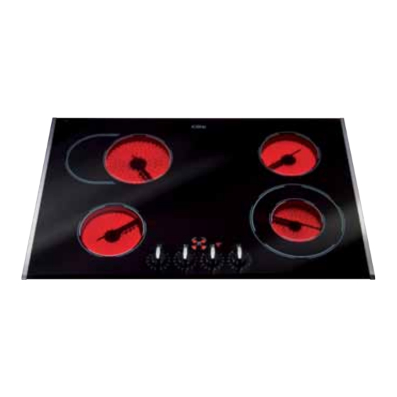
BEFORE USING FOR THE FIRST TIME • Read the instructions carefully before installing and using the appliance • After unpacking the appliance, make sure it is not damaged. In case of doubt, do not use the appliance and contact your supplier or a qualified engineer. •... - Page 4 FEATURES 60 cm models Fig. 1.1 Fig. 1.2 9 10 9 10 Electrical insulation Class I Electrical insulation Class I COOKING POINTS COOKING POINTS (Fig. 1.1) (Fig. 1.2) 1. Hi-light cooking zone Ø 140 mm 1. Hi-light cooking zone Ø 180 mm - 1200 W - 1800 W 2.
- Page 5 80 cm models Fig. 1.3 9 10 Electrical insulation Class I COOKING POINTS (Fig. 1.3) 1. Hi-light cooking zone Ø 140 mm - 1200 W 2. Oval double hi-light cooking zone Ø 180 x 260 mm - 800/2200 W 3. Hi-light cooking zone Ø 140 mm - 1200 W 4.
- Page 6 90 cm models Fig. 1.4 Electrical insulation Class I COOKING POINTS (Fig. 1.4) 1. Hi-light cooking zone Ø 180 mm - 1800 W 2. Hi-light cooking zone Ø 140 mm - 1200 W 3. Oval double hi-light cooking zone Ø 180 x 260 mm - 800/2200 W 4.
-
Page 7: Important Note
HOW TO USE THE HOB The ceramic surface of the hob allows a fast transmission of heat in the vertical direc- tion, from the heating elements underneath the ceramic glass to the pans set on it. The heat does not spread in a horizontal direction, so that the glass stays “cool” at only a few centimeters from the cooking plate. - Page 8 HI-LIGHT DOUBLE ZONE and HI-LIGHT OVAL ZONES The heating element is formed of a 2 coils of resistant material which reaches the work- ing temperature quickly. These zones are controlled by a continuous energy regulator switch (figs. 2.3a - 2.3b). The heat intensity can be regulated continuously from “0”...
- Page 9 CO0KING HINTS Cooking zone Knob knob TYPE OF COOKING setting setting Switched OFF For melting operations (butter, chocolate). To maintain food hot and to heat small quantities of liquid (sauces, eggs). To heat bigger quantities; to whip creams and sauces. (vegetables, fruits, soups).
-
Page 10: Residual Heat Indicators
RESIDUAL HEAT INDICATORS The hob also features 4 or 5 warning lamps which are wired to the corresponding plate. When the temperature of a cooking plate is over 60°C, the relevant warning lamp is also lit- up to warn of heat on the surface of the hob. These lamps also stay on after the cooking plates have been switched off to shown that the hob surface is still hot. -
Page 11: Safety Hints
SAFETY HINTS DISTORTED • Before you switch the hob on, make PANBASE sure you know which knob controls the WRONG required cooking zone. We advise you to set the pan over the cooking zone before switching it on. • Do not use pots and pans with rough DISTORTED bases (pay attention to cookware made PANBASE... -
Page 12: Cleaning The Ceramic Hob
CLEANING THE CERAMIC HOB Before you begin cleaning make sure that the hob is switched off. • Remove spillages and other types of incrustations. • Dust or food particles can be removed with a damp cloth. • If you use a detergent, please make sure that it is not abrasive or scouring. Abrasive or scouring powders can damage the glass surface of the hob. - Page 13 ADVICE FOR THE INSTALLER...
- Page 14 INSTALLATION CAUTION: • This appliance shall only be serviced by authorized personnel. • This appliance is to be installed only by an authorised person according to the cur- rent local regulations and in observation of the manufacturer’s instructions. • Incorrect installation, for which the manufacturer accepts no responsibility, may cause personal injury of damage.
- Page 15 This cooktop can be built into a working surface 30 to 40 mm thick and 600 mm deep. In order to install the ceramic hob into the kitchen fixture, a hole with the dimensions shown in figures 3.1a,b,c has to be made, keeping in consideration the following: •...
-
Page 16: Fastening The Cooktop
FASTENING THE COOKTOP Each cooktop is supplied with a set of tabs and screws to fasten it on units with a work- ing surface from 3 to 4 cm deep. The kit includes 4 tabs A and 4 self-threading screws B (fig. 3.4). •... -
Page 17: Electrical Connection
ELECTRICAL CONNECTION for the UNITED KINGDOM only IMPORTANT: Installation must be carried out according to the manufacturer's instructions. Incorrect installation may cause harm and damage to people, ani- mals or property, for which the manufacturer accepts no responsibility. Before carrying out any work on the electrical section of the appliance, it must be disconnected from the mains. - Page 18 • The wires in the mains lead are coloured in accordance with the following code: Green & Yellow = Earth Blue = Neutral Brown = Live. As the colours of the wires in the mains lead for the appliance, may not correspond with the coloured markings identifying the terminals in your spur box, proceed as fol- lows: 1) The wire which is coloured green and yellow must be connected to the terminal...
- Page 19 CONNECTING THE FEEDER CABLE To connect the feeder cable to the hob it is necessary to carry out the following opera- tions: • Unscrew the screw A of the terminal board at the bottom of the hob (fig. 4.1). • Unlock the 2 clips B and open the cover C.
-
Page 20: Electrical Requirements
for the other countries IMPORTANT: Installation must be carried out according to the manufacturer's instructions. Incorrect installation may cause harm and damage to people, ani- mals or property, for which the manufacturer accepts no responsibility. Before carrying out any work on the electrical section of the appliance, it must be disconnected from the mains. - Page 21 CONNECTING THE FEEDER CABLE To connect the feeder cable to the hob it is necessary to carry out the following opera- tions: • Unscrew the screw A of the terminal board at the bottom of the hob (fig. 4.4). • Unlock the 2 clips B and open the cover C.
- Page 22 220 - 240 V N L2 N (L 380 - 415 V 2N 220-240 V Fig. 4.6 380 - 415 V 3N 380-415 V 2N Fig. 4.5 Fig. 4.7 380-415 V 3N Fig. 4.8...
- Page 24 Descriptions and illustrations in this booklet are given as simply indicative. The manufacturer reserves the right, considering the characteristics of the models described here, at any time and without notice, to make eventual necessary modifications for their construction or for commercial needs. Cod.
Need help?
Do you have a question about the HVC70 and is the answer not in the manual?
Questions and answers