Table of Contents
Advertisement
Quick Links
Advertisement
Table of Contents

Subscribe to Our Youtube Channel
Related Manuals for CDA HVN 32 Series


Summary of Contents for CDA HVN 32 Series
- Page 1 Induction Cooking Hob Manual for Installation, Use and Maintenance Customer Care Department • The Group Ltd. • Harby Road • Langar • Nottinghamshire • NG13 9HY T : 01949 862 012 F : 01949 862 003 E : service@cda.eu W : www.cda.eu...
-
Page 2: Appliance Information
The CDA Group Ltd cannot be held responsible for injuries or losses caused by incorrect use or installation of this product. Please note that CDA reserve the right to invalidate the guarantee supplied with this product following incorrect installation or misuse of the appliance. -
Page 3: Before Using For The First Time
Before Using for the First Time – Read the instructions carefully before installing and using the appliance. – After unpacking the appliance, make sure it is not damaged. In case of doubt, do not use the appliance and contact your supplier or a qualified engineer. –... - Page 4 Important Safeguards and Recommendations – Do not carry out any cleaning or maintenance without first disconnecting the appliance from the electrical supply. – During and after use of the hob, certain parts will become hot. Do not touch hot parts. –...
-
Page 5: Features And Technical Data
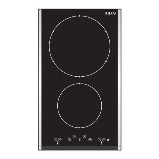
Features and Technical Data Fig. 1 Cooking Zones 1. Induction cooking zone Ø 140 mm - 1400 W 2. Induction cooking zone Ø 210 mm - 2200 W (3000 W with Booster function) Note: The Nominal and Booster Power may change depending on the size and material of the pan set on the cooking zone. -
Page 6: Use Of Induction Hob
Any time the cooktop is connected to the electrical supply or after a power failure (that generates a reset in the user interface), the first time the Key-Lock sensibility of the keyboard is readjusted. -
Page 7: Thermal Protection
Thermal Protection The induction cooktop is fitted with safety devices to protect the electronic system and each cooking zone from overheating. Overheating of Cooking Zone – Cooking zone OFF: the cooking zone display shows " and " " alternating or just "... - Page 8 The ceramic cooktop is fitted with induction cooking zones. These zones, shown by painted disks on the ceramic surface, are controlled by a touch control system. Induction Cooking System When your induction hob is switched on and a cooking zone has been selected, the electronic circuits produce induced currents that instantaneously heat the bottom of the pan which then transfers this heat to the food.
- Page 9 How To Turn the Touch Control ON and OFF Switching ON Press the key and keep it pressed until the touch control is lighted. The displays of the cooking zones read " Notes: – If the safety key-lock protection is active, the touch control can be turned ON only after having deactivated this protection.
- Page 10 Power Ignition and Adjustment of a Cooking Zone To turn ON a cooking zone the touch control must be switched ON (see section “ How To Turn the Touch Control ON and OFF ”). Press the key and keep it pressed until the desired power level, ranging between As an alternative, press the key level...
- Page 11 " Induction Heaters Power Management The maximum power of the cooktop is limited to 3600 W. This means that the electronic interface automatically manages the power levels of the heaters in order to not exceed the maximum power limit (see also table on the previous page).
- Page 12 – Cooking zone/s operating (power level already set) - with the key-lock protection active it is only possible to switch off the cooktop. – Cooktop off - with the key-lock protection active it is not possible to use the cooktop. To use the cooktop deactivate this protection.
- Page 13 Program for Automatic Switching OFF of One Cooking Zone This function permits to set a timer from automatic turning OFF of one cooking zone only. Note: It is not possible to set this program for both the cooking zones. With the touch control switched ON: –...
- Page 14 Operation Time Limit of Cooking Zones Each cooking zone is automatically switched OFF after a maximum preset time if no operation is performed. The maximum preset time limit depends on the set power level, as illustrated in this schedule. Each operation on the cooking hob by using the keys reset the maximum operation time at its initial value.
- Page 15 4. If the problem does not disappear repeat step from 1 to 3. 5. If the problem continues, disconnect the cooktop from the mains and contact your Authorised Service Centre. Important: In the case of error message "...
-
Page 16: Cleaning And Maintenance
Cleaning and Maintenance Cleaning the Ceramic Hob – Before you begin cleaning make sure that the hob is switched off. – Remove spillages and other types of incrustations. – Dust or food particles can be removed with a damp cloth. –... -
Page 17: Tips For Installation
– Incorrect installation, for which the manufacturer accepts no responsibility, may cause personal injury of damage. – Always disconnect the cooktop from mains power supply before carrying out any maintenance operations or repairs. WARNING ! –... - Page 18 This cooktop can be built into a working surface 30 to 40 mm thick and 600 mm deep. In order to install the ceramic hob into the kitchen fixture, a hole with the dimensions shown in figure 3 has to be made, keeping in consideration the following: –...
-
Page 19: Fastening The Cooktop
Fastening the Cooktop Each cooktop is supplied with a set of tabs and screws to fasten it on units with a working surface from 3 to 4 cm deep. The kit includes 4 tabs A and 4 self-threading screws B (fig. 6). -
Page 20: Mains Electricity Connection
Mains Electricity Connection Incorrect installation may be dangerous and the manufacturer can not be held responsible. Warning! This appliance must be earthed The manufacturer declines all responsibility for any problem caused by failure to observe this rule. THIS APPLIANCE MUST BE CONNECTED TO THE MAINS SUPPLY BY A COMPETENT PERSON, USING FIXED WIRING VIA A DOUBLE POLE SWITCH AND PROTECTED BY A SUITABLE FUSE. - Page 21 Connection of the Power Supply Cable Unhook the terminal board cover by inserting a screwdriver into the two hooks A (fig. 8). Open the cable gland by unscrewing screw F (fig. 9), unscrew the terminal screws and remove the cable. The new supply cable, of suitable type and section, is connected to the terminal board following the diagram of fig.
-
Page 22: Appliance Servicing
Appliance Servicing CDA provide a quality and effective after-sales service to cover all your servicing needs. Please attach your receipt to this page for safekeeping. Please help us to help you by having the following information available when booking a service-call: 1. - Page 24 Customer Care Department • The Group Ltd. • Harby Road • Langar • Nottinghamshire • NG13 9HY T : 01949 862 012 F : 01949 862 003 E : service@cda.eu W : www.cda.eu...
Need help?
Do you have a question about the HVN 32 Series and is the answer not in the manual?
Questions and answers