Table of Contents
Advertisement
Quick Links
Advertisement
Table of Contents

Subscribe to Our Youtube Channel
Related Manuals for Idis DR-2100P Series


Summary of Contents for Idis DR-2100P Series
- Page 1 Network Video Recorder Operation Manual DR-2100P Series Powered by...
-
Page 2: Safety Precautions
Before reading this manual This operation manual contains basic instructions on installing and using DirectIP™ Network Video Recorder, an IDIS product. Users who are using this product for the first time, as well as users with experience using comparable products, must read this operation manual carefully before use and heed to the warnings and precautions contained herein while using the product. -
Page 3: Important Safeguards
Before reading this manual Important Safeguards 1. Read Instructions 14. Damage requiring Service All the safety and operating instructions should be read before the Unplug this equipment from the wall outlet and refer servicing to qualified appliance is operated. service personnel under the following conditions: 2. - Page 4 Before reading this manual In-Text Symbol Type Description Caution Important information concerning a specific function. Note Useful information concerning a specific function. User’s Caution Statement Caution: Any changes or modifications to the equipment not expressly approved by the party responsible for compliance could void your authority to operate the equipment.
- Page 5 © 2013 IDIS Co., Ltd. IDIS Co., Ltd. reserves all rights concerning this operation manual. Use or duplication of this operation manual in part or whole without the prior consent of IDIS Co., Ltd. is strictly prohibited. Contents of this operation manual are subject to change without prior notice.
-
Page 6: Table Of Contents
Table of Contents Part 1 – Introduction ....... . . 9 Product Features . - Page 7 Table of Contents Remote Control Buttons during Playback ........32 Context Menu .
- Page 8 Part 5 - IDIS Web ........
-
Page 9: Part 1 - Introduction
Part 1 – Introduction Product Features This is a DirectIP™-enabled video recorder that supports surveillance, video recording, and video playback using a network of cameras. This NVR (Network Video Recorder) unit offers the following features: • Real-time 4/8/16-channel DirectIP™ network surveillance •... -
Page 10: Accessories
Upon unpackaging the product, check the contents inside to ensure that all the following accessories are included. DR-2100P Series Power Cable / DC Adapter(12V, 48V) Quick Guide Operation Manual and IDIS Center Optical USB Mouse IR Remote Control Program CD Assembly Screws for Adding Hard... -
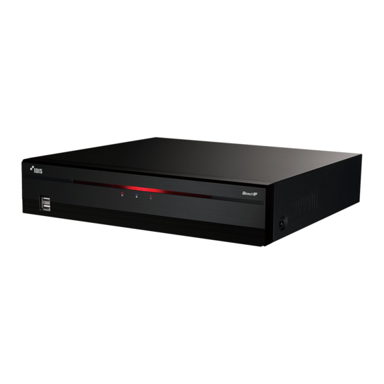
Page 11: Overview
Part 1 – Introduction Overview Front Panel USB Ports LEDs • Remote control sensor is located on the bottom center of the front panel. Ensure that the sensor remains unobstructed at all times. If obstructed, the sensor might not be able to receive remote control signals. •... - Page 12 Part 1 – Introduction 2 LEDs • Power LED: Lights up while the main unit is in operation. • HDD LED: Flashes when data is being written on the HDD or a video search is in progress. Network LED: Flashes when linked remotely over an ethernet. •...
-
Page 13: Rear Panel
Part 1 – Introduction Rear Panel Factory Reset Button Audio Ports VGA Out Port HDMI Out Port Video In / PoE Ports Network Port Video In / Ext. Port Alarm Connection Ports RS232 Port Power In Port (12V) Power In Port (48V) Rear Panel Connections Monitor Connection Video Connection... - Page 14 Part 1 – Introduction • Video In/Ext. Port Alarm Connection Connect alarm connectors to these ports. This port does not support PoE. It's possible to establish a network with network cameras and external hubs using Cat5, Cat5e, and Cat6 cables. •...
- Page 15 Part 1 – Introduction • Connector Arrangement Factory Reset ALARM IN Alarm In 1 through 4 1 through 4 Ground ALARM OUT COM Relay Common Located next to the Audio Out port on the rear of the NVR is a switch that, once activated, will reset the Normally Open Relay Alarm ALARM OUT NO NVR to all its initial factory settings.
- Page 16 Part 1 – Introduction Connections on the Rear Panel Speaker VGA Monitor Camera DirectIP™ Gigabit PoE Switch HDMI Monitor Camera Alarm Network Sensor IDIS Center Power (48V) Remote Power (12V) Keyboard Monitoring...
-
Page 17: Remote Control
Part 1 – Introduction Remote Control ID Button PANIC Button Camera Buttons STATUS Button LAYOUT Button PTZ Control Buttons REGISTER MODE Button THUMBNAIL Button CALENDAR Button KEYLOCK Button SETUP Button FREEZE Button LOG Button Enter Button Arrow Buttons ALARM Button SEQUENCE Button &... - Page 18 Part 1 – Introduction 1 ID Button 9 CALENDAR Button Used to assign remote control ID values. Displays a video recording playback screen that includes a calendar. No additional remote control assignment is necessary if the system's ID is 0. If the system's 0 KEYLOCK Button ID is a number between 1 and 9, however, you Locks out all remote control keys.
- Page 19 Part 1 – Introduction ( PTZ Button Initiates PTZ mode and allows you to control the selected PTZ camera. ) VIEW Button Pressing the VIEW button while in PTZ mode displays the preset list. a SAVE Button Press the SAVE button while in PTZ mode to save the current position as a preset.
-
Page 20: Part 2 - Getting Started
Part 2 - Getting Started Setup Wizard Quick Wizard Setup Wizard lets you configure basic settings Select Quick Wizard. required for operating the system. Setup Wizard only appears during initial booting. To use Wizard after initial booting, go to the system menu and select General >... - Page 21 Part 2 - Getting Started Choose the desired Recording Method and click – Recording resolutions used under each recording method and record video quality setting are as follows: Next. High Video Standard Longer Quality Priority Recording Recording Time Profile Profile Priority Profile Motion Event...
- Page 22 NVR. Once registered, the name can be used to access the NVR directly from clients Select Network Configuration and then click such as the IDIS Center. Check the name's Next. Select either Auto Configuration or Manual availability to complete the registration Configuration and then click Test to test the process.
-
Page 23: Camera Registration
Part 2 - Getting Started Camera Registration Once Network Setup Wizard is complete, the system will automatically enter Camera Registration mode and scan for cameras connected to the NVR. – Run DHCP Server: Allocates IP automatically to the camera connected to VIDEO IN port using DHCP. -
Page 24: Camera View Buttons
Part 2 - Getting Started Camera List Area • Only cameras that are connected to the NVR via VIDEO IN ports can be scanned and registered. • Selecting Auto Scan (LAN) as the mode scans for network devices matching the selected protocol. -
Page 25: Video Display Area
Part 2 - Getting Started Video Display Area • Information is not indicated on the bottom of the screen for cameras already registered to the NVR, and the Screen Position/Registration Info icon Left-click on the video display area to toggle between is shown with a black background. -
Page 26: Camera Registration Mode
Part 2 - Getting Started Camera Registration Mode Login While in Live mode, right-click and select Camera Configuring the NVR's settings and accessing its Registration. searching and other functions require an authorized user login. Bring up the Live menu and either press the SETUP button on the remote control or click on (Login) using the mouse. -
Page 27: Live Mode
Part 2 - Getting Started Live Mode Live Menu Press the MENU button on the remote control while in Live mode to bring up the Live menu on the top of the screen. Press MENU button once more to hide the menu. Use the Arrow buttons on the remote control to select the menu options. -
Page 28: Zoom
Part 2 - Getting Started Full Sequence # Status Indication Sequence Displays system status icons. Displays all channels in sequence while in Live mode (single and split screen settings). In order to use the Full Sequence feature, Full Sequence (Display Setup Status Indication - Main Monitor >... -
Page 29: Ptz Control
Part 2 - Getting Started PTZ Control Setting Up a PTZ Preset While in PTZ mode, select the VIEW button on the While in Live mode, right-click and select PTZ from the remote control to display the Set Preset window and context menu or press the PTZ button on the remote assign the current position as a preset. -
Page 30: Event Monitoring
Part 2 - Getting Started Event Monitoring Advanced Settings In PTZ mode, selecting a camera and then clicking When an event occurs, the NVR automatically displays Menu button loads the Advanced PTZ screen as shown below. This menu lists Speed, Auto Pan, and the channel linked to the event and shows the icon on the system status area on the upper right other advanced PTZ camera control options available... -
Page 31: Context Menu Access
Part 2 - Getting Started Video Recording Context Menu Access While in Live mode, press the remote control's Video recording will only take place if all the button and then the Menu button to display the connections are made correctly as per information Context Menu window. -
Page 32: Audio Recording
Part 2 - Getting Started Audio Recording Remote Control Buttons during Playback If the Record Audio option under Record Setup > General has been enabled, the camera will record audio along with video. For more information, refer to Camera Button: Displays the selected recording the Audio on page 46, Record Setup on page in full screen. -
Page 33: Part 3 - Configuration
Part 3 - Configuration Menu Use Change the setting and then select Apply or OK to save the change. To apply default settings, select the Default button Information contained in this section (Menu Use) located on the left bottom corner of the setup applies to all other instructions found throughout Part window. -
Page 34: Mouse
Part 3 - Configuration Mouse If an upgrade attempt fails, an upgrade failure message will be displayed. Refer to Error Code Types on page 78 for more details. Using a mouse makes it easier to configure the settings. A mouse lets you make selections faster and use its wheel to scroll through long menus. -
Page 35: Date/Time
Part 3 - Configuration • Time Zone: Used to designate the system's time In order to display the system_log.txt file, you must zone. use the correct character encoding settings and use a fixed-width font. Refer to the map displayed on the screen and change the time zone using the mouse or the arrow •... -
Page 36: User
Part 3 - Configuration Select OK to apply and exit. Select + User and then enter a user name. Select a group for the user and then enter a password. The password can be up to 16 characters in length and may include letters, symbols, and numbers. - Page 37 Part 3 - Configuration Group Permissions System Shutdown May shutdown the system from the system menu. Upgrade May upgrade the system from the system menu (System Setup). May adjust each camera's brightness, contrast, saturation, and hue Color Control settings. System Check May view System Check results.
-
Page 38: Storage
Part 3 - Configuration Storage Monitoring Use this option to configure storage settings. Use this option to configure Monitoring settings. • Settings: Configure when and what the system • Type: Indicates the type of the installed disk. should monitor for. •... - Page 39 Part 3 - Configuration Monitoring Options Define monitoring times. If self-diagnosis is not performed on a regular basis, the System system will assume an error. Panic Record Define panic recording actions. The system will assume an error if the system has been scheduled to record normally but recording does not take place during scheduled intervals.
-
Page 40: Camera Setup
Part 3 - Configuration Camera Setup Advanced Setup Configure security and other advanced camera Refer to the Menu Use on page 33 for basic settings. information on using the Setup menus. General Enable/disable and rename cameras. • Video: Adjust the camera image sensor settings such as white balance and exposure. - Page 41 Part 3 - Configuration • Set: Choose a preset number and then enter a Types of configuration options shown vary depending on the PTZ functions supported by the name. This saves the current preset under the camera. specified preset number and name. •...
- Page 42 Part 3 - Configuration • Set: Used to set up a tour profile. 3 Pattern Used to set up a pattern profile for the camera to follow along. - Name: Enter a name for the tour profile. • Start recording: Select a pattern number, - No.: Indicates the order of the function in the enter a name for the pattern, and then click OK tour sequence.
- Page 43 Part 3 - Configuration 6 Auto Run: Specify which action to take if the camera has not been controlled for the specified duration of time. 7 Auto Pan: Specify the camera's panning direction. When Auto Pan is selected from • Edit: Rename the selected privacy masking area. a remote program, the camera pans in the •...
- Page 44 Part 3 - Configuration • IR Mode: IR Mode blocks out the infrared White Balance Options spectrum. You can ensure clear images at all times by blocking out the infrared spectrum in high-lighting conditions and allowing the infrared spectrum to pass through in low-lighting conditions.
-
Page 45: Stream
Part 3 - Configuration • Local Exposure: Activate Local Exposure. Use Stream Local Exposure on images that appear too dark due to backlighting conditions and on images containing over-exposed sections. Greater the value, clearer the image. e.g.) Dark parking lot entrances and gas station entrances at night (Local Exposure compensates for the bright light coming from incoming vehicle headlights and makes it possible... -
Page 46: Audio
Part 3 - Configuration Audio Configure audio recording settings for all cameras simultaneously. • If an upgrade attempt fails, an upgrade failure message will be displayed. Refer to Error Code Types on page 78 for more details. • The camera will reboot after the upgrade and then reconnect automatically. -
Page 47: Schedule
Part 3 - Configuration • Auto Deletion: Configure this option to delete Schedule recording data automatically after the specified number of days has elapsed. Select between 1 day and 999 days. To disable Auto Deletion, select Never. If enabled, recording data will be stored on the NVR for the specified number of days and then deleted automatically. -
Page 48: Pre-Event
Part 3 - Configuration Simple Mode Options Advanced Mode Options • Mode: Select No Record, Time, Event, or Time Select to configure event types and video profiles. & Event. • Type: Event-specific and time recording icons are as follows: Unless the Panic Record button is Time Lapse pressed, no recording will take place Audio Detection... -
Page 49: Event Setup
Part 3 - Configuration • If no event mode schedule exists in the schedule, a warning message prompting you to add an event mode schedule will be displayed. • The warning message will appear even in Time & Event mode. Event Setup Use the remote control's arrow buttons to move the block selection window up, down, left, and right. - Page 50 Part 3 - Configuration • Min. Blocks: Motion needs to be detected in more Trip Zone than the specified number of blocks in order to trigger a Motion Detection event. You may select a value between 1 and the number of blocks selected under Zone for daytime and nighttime, each.
- Page 51 Part 3 - Configuration - Reverse: Clear the blocks selected within the • Daytime Setup: Specify when daytime starts selection window and select all unselected blocks and ends. Adjust the time frame in 15-minute within the selection window. increments. Times outside the specified range will be assumed as nighttime by the system.
-
Page 52: Alarm-In
Part 3 - Configuration Alarm-In Video Loss • No.: Enable / disable alarm-ins. • Actions: Specify which actions to take when a Video Loss event occurs. This option includes both local and network camera - Record: Specify which cameras to begin linked alarm-ins. -
Page 53: Text-In
Part 3 - Configuration • Activation Time: Specify how long audio detection has to last in order for it to be considered an event. Audio detections that do not last for the specified duration of time will not be considered as events. •... -
Page 54: Device Setup
Part 3 - Configuration Device Setup • Time Out: Once Time Out has been enabled, the system will assume the end of a transaction if no new string is entered within the specified duration of Refer to the Menu Use on page 33 for basic time. -
Page 55: Network Setup
• To use the UPnP (Universal Plug and Play) feature, select Use UPnP. If using an IP router (or NAT), • IDIS Web: If you wish to use IDIS Web, select IDIS UPnP service allows the device to automatically Web - Use IDIS Web Service. Select IDIS Web - forward the port to the NVR. -
Page 56: Fen
• If the device name contains the #, \, and/or % symbol, it might not be able to connect to the NVR • With DHCP, the NVR's IP address might change from the IDIS Web program. with each startup. • Status: Used to check the status of the device There is a limit to the number of users allowed to being registered to the FEN server. -
Page 57: Notification Setup
Part 3 - Configuration Notification Setup Callback Configure Callback settings. Schedule Select the + icon at the lower left corner of the screen to add a notification schedule. Enter the IP address of the receiving server and set Retry to between 1 and 10 in case of connection failure. -
Page 58: Sns
Part 3 - Configuration Select MP4 Clip to attach event recordings to Select OK to apply and exit. outgoing mails. This product contains content developed by The event recordings generated by a camera can OpenSSL Project for use in Open SSL Toolkit (http:// be attached only. -
Page 59: Push
Part 3 - Configuration Push Status • Date and Time: Displays the date and time. Configure Push settings. Camera • No.: Displays the camera number on the upper left corner of the camera screen. • Title: Displays the camera name on the upper left corner of the camera screen. -
Page 60: Status Setup
Part 3 - Configuration Status Setup Refer to the Menu Use on page 33 for basic information on using the Setup menus. Event This screen displays an overview of all events. When an event occurs, the corresponding channel flashes for 5 seconds. Event Types Alarm-In Check Alarm-In... -
Page 61: Storage
Part 3 - Configuration Storage Indicates each disk's status. Configure Disk Bad and Disk Temperature settings under Setup > System > Monitoring. Not Formatted A disk that has never been used before. • Disk performing normally. Good • If the HDD is partially damaged, indicates the bad sector Disk Bad percentage. -
Page 62: Network
Part 3 - Configuration Network This page provides a complete overview of the network status in real-time. Information shown include camera connection status, LAN port link status, power consumption, number of connected clients, and network connection info. Camera Connection indicates the camera is connected. indicates the camera is not connected. -
Page 63: Part 4 - Search
Search Part 4 - Search Time-Lapse Search While in Live mode, select the Search Mode icon and select Time-Laspe Search or Event Log Search. Select MENU button on the remote control while in Search mode to display a menu from which you can select Control Area. -
Page 64: Search Menu
Part 4 - Search Search Menu 4 5 6 7 8 9 1 Layout Used to change the screen layout to single screen, 2x2, 3x3, or 4x4. 2 Previous/Next Group Loads the previous/next screen group. 3 Display • OSD On/Off: Enables/disables the OSD feature. •... - Page 65 Part 4 - Search CAM3 4 5 6 7 8 1 Bookmark • Select the icon to add a bookmark to the current playback position. • Select a bookmark from the Bookmark setup window on the right side of the Time-Lapse Search mode screen to move to the registered playback position.
- Page 66 Part 4 - Search 4 Event Search • Farther back the data is on the record table, the Selecting Event Search provides Motion Search and more recent it is. Text-In Search options. • If the system's clock is changed to a previous •...
-
Page 67: Context Menu
Part 4 - Search Context Menu • Type: Motion Search looks for motion in the selected area by comparing individual frames against their preceding frames. This means slow Select the Menu button or right-click on the Camera and gradual movements, no matter how long screen to access the context menu. -
Page 68: Clip Copy
Part 4 - Search Select Option... to configure Text-In Search options. • Channels: Specify which channel to save the recording to. • Select First under From and Last under To • Password: Enable password protection for the to search the recording from start to finish. saved video clip and assign a password. -
Page 69: Print
Event Log Search One-Touch Clip Copy files is 2GB. • Clip Copy files can be played back on Windows systems. For more information, refer to the IDIS Select Search Mode > Event Log Search to bring Center operation manual. up the Event Log Search window. -
Page 70: Overlapped Recording Search
Part 4 - Search • Use event filters to include/exclude specific system When searching overlapped video recordings, you can events such as Panic Record, Check Recording, choose a specific point in time or a time frame. If you Check Alarm-In, Disk Almost Full, Disk Bad, use the Go to the Date/Time option and select a Disk Temperature, Disk S.M.A.R.T., Fan Error point within the overlapped time period (4 o'clock, for... -
Page 71: Part 5 - Idis Web
IDIS Web program. • If running IDIS Web, the bottom section of the screen may get cut off if the address bar or the status bar is shown. In this case, change Internet Options so that the address bar or the status bar is hidden. (Tools →... -
Page 72: Web Live Mode
Part 5 - IDIS Web • Launching a new version of IDIS Web for the first time can cause Internet Explorer to load information from the previous version. In this case, navigate to Tools → Internet Options → General, delete temporary Internet files, and then restart IDIS Web. - Page 73 Part 5 - IDIS Web Click to print the current video screen using a printer connected to the computer. Click to save the current video screen as an image file. Click to configure rendering mode and OSD settings. Select rendering mode to adjust the video output rate or select which OSD elements to display on the screen from the OSD list.
-
Page 74: Web Search Mode
& Press to terminate IDIS Web. Place the mouse pointer on the logo to check IDIS Web's version. Displays time information of the video recording from the remote DVR. Select the desired mode. Click to print the current video screen using a printer connected to the computer. - Page 75 Part 5 - IDIS Web Click to switch over to Web Live mode. Shows login information. Select the camera you wish to search. Use the arrow buttons to navigate to the previous/next camera group. Zoom in or out on the video.
- Page 76 Part 5 - IDIS Web Select a camera from the screen and right-click to bring up the pop-up menu. • Change Camera Title: Used to change the camera's name. Renaming the camera in Web Search mode does not affect the camera's name on the remote system.
-
Page 77: Part 6 - Appendix
Part 6 - Appendix System Log Types Boot Up Panic On System Shutdown Panic Off Restart Clear All Data Upgrade Success Clear Disk Upgrade Error Format Disk Power Failure Disk Full Time Changed Auto Deletion Time Zone Change Search Begin Time Sync. -
Page 78: Error Code Types
Part 6 - Appendix Error Code Types Upgrade Error Codes Type Type Unknown Error Remote Network Error Incorrect File Version No Remote Upgrade Permission Incorrect OS Version Remote Upgrade File Save Failure Incorrect Software Version Remote Upgrade Cancelled by User Incorrect Kernel Version USB Storage Device Mount Failure Storage Device Mount Failure... - Page 79 Part 6 - Appendix Network Error Codes Type Type Cause of Failure Unknown Connection Cancelled by User Normal Logout No Response from Network Device Host All Channels in Use - Connection Denied High Network Noise Level Incorrect Product Version Info Transmission Queue Full Incorrect User Name or Password Incorrect OEM Info...
-
Page 80: Troubleshooting
Part 6 - Appendix Troubleshooting Problem Solution • Check the power cable connection status. The main unit won't turn on. • Check the power outlet. • Check the camera's video cable connection status. • Check the monitor's video cable connection status. Unable to display Live video. -
Page 81: Specifications
Part 6 - Appendix Specifications These product specifications may change without prior notice. General Exterior Dimensions 300mm x 61mm x 231mm (W x H x D) Weight (Main Unit) 2.3kg (with 2HDDs) Weight (Packaging) 4.5kg (with 2HDDs) Packaging Dimensions 460mm x 113mm x 360mm (W x H x D) Working Temperature 5°C –... - Page 82 Part 6 - Appendix Connectors Video In Ethernet: 4/9/9 ports Camera Power Out Ethernet: 4/8/8 ports HDMI: 1 HDMI Monitor Out VGA: 1 DB15 Audio Out 1 RCA connector Alarm Terminal block Ethernet Port 1 RJ-45 RS232 Serial Port Terminal block, text insertion (POS/ATM) IR Remote Control Port Remote Control USB Ports...
-
Page 83: Index
Alarm-Out Pre-Event Audio Recording Print PTZ Control Camera Registration Clip Copy Recording Record Setup Event Monitoring Schedule Search Storage Stream IDIS Web Text-In IP Address Text-In Search Timelapse Mode Live Mode Login Upgrade Motion Search Video-Analytics Mouse Wizard Ver. 1.1... - Page 84 IDIS Co., Ltd. For more information, please visit at www.idisglobal.com...
Need help?
Do you have a question about the DR-2100P Series and is the answer not in the manual?
Questions and answers