Vertex VXR-1000 Service Manual
Vhf vehicular cross-band repeater
Hide thumbs
Also See for VXR-1000:
- Specifications (2 pages) ,
- Service manual (48 pages) ,
- Accessory installation manual (2 pages)
Table of Contents
Advertisement
Quick Links
Vehicular
Cross-band Repeater
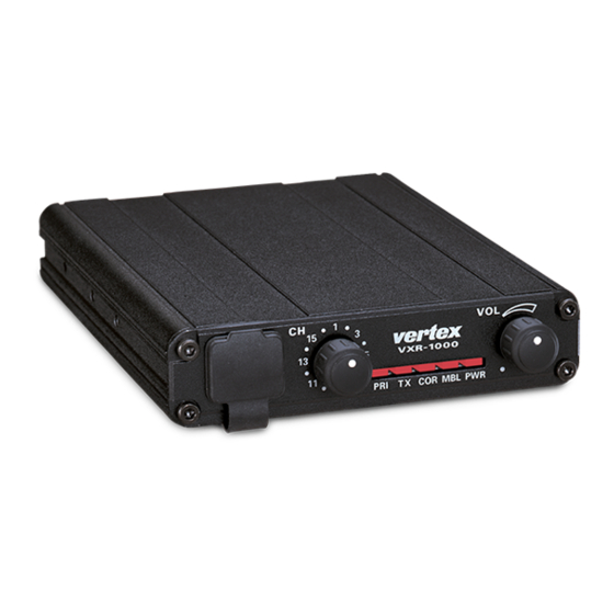
VXR-1000
Service Manual
©2009 VERTEX STANDARD CO., LTD.
The VXR-1000 Series is designed to provide extended handheld coverage by repeating transmissions
in both directions through an existing high power mobile radio.
Reliability is assured by a highly integrated surface mount circuit design and a aluminum extrusion
chassis. Important channel frequency data is stored in EEPROM, and is easily programmable by
dealers using a personal computer and the Vertex VPL-1 Programming Cable and CE-22 Software.
Please take a few minutes to read this manual carefully. The information presented here will allow
you to derive maximum performance from your VXR-1000. After reading it, keep the manual handy
for quick reference, in case questions arise later on.
We're glad you joined the Vertex team. Call on us any time, because our business is communications.
Let us help you get your message across.
Operating Manual Reprint ........................ 2
Specifications ............................................... 4
Installations .................................................. 5
Interconnection with
Vertex VX- Series Transceiver ........ 7
Vxr-1000 Trunking Interface Manual ....... 11
CE-22 Programming Software .................. 14
(VHF)
E137190B
Contents
VERTEX STANDARD CO., LTD.
4-8-8 Nakameguro, Meguro-Ku, Tokyo 153-8644, Japan
VERTEX STANDARD
US Headquarters
10900 Walker Street, Cypress, CA 90630, U.S.A.
YAESU UK LTD.
Unit 12, Sun Valley Business Park, Winnall Close
Winchester, Hampshire, SO23 0LB, U.K.
VERTEX STANDARD HK LTD.
Unit 5, 20/F., Seaview Centre, 139-141 Hoi Bun Road,
Kwun Tong, Kowloon, Hong Kong
VERTEX STANDARD ( AUSTRALIA ) PTY., LTD.
Normanby Business Park, Unit 14/45 Normanby Road
Notting Hill 3168, Victoria, Australia
Exploded View & Miscellaneous Parts ........ 25
Block Diagram .............................................. 26
Circuit Description ...................................... 27
Alignment ...................................................... 29
Repeater Cloning.......................................... 32
Board Unit (Schematics, Layouts & Parts)
Main Unit ............................................................... 33
1
Advertisement
Table of Contents

Subscribe to Our Youtube Channel
Related Manuals for Vertex VXR-1000


Summary of Contents for Vertex VXR-1000
- Page 1 Please take a few minutes to read this manual carefully. The information presented here will allow you to derive maximum performance from your VXR-1000. After reading it, keep the manual handy for quick reference, in case questions arise later on.
-
Page 2: Operating Manual Reprint
Detect/Mobile COR Indicator Audio Microphone PTT This lamp blinks red when the VXR-1000 is Antenna Socket receiving a signal from a handheld, and glows The Antenna socket is a standard 50 Ω BNC red while the VXR-1000 is receiving a sub- antenna connector. - Page 3 “on-air detect” line from the mobile. If Short: low level output (0-100 mV)*; the VXR-1000 does not see the radio transmit at open: high level output (0-5 V). all (system is busy), it will send a low tone to the JP1001/1002/1003: handheld to alert you that the system is busy.
-
Page 4: Specifications
Specifications GENERAL Frequency Range: 150 - 174 MHz (Receive frequencies within a ±5 MHz spread over the range 150 - 174 MHz) Number of Channels: 16 Channels Channel Spacing: 12.5/25 kHz Supply Voltage: 13.8V DC, negative ground −30 °C to +60 °C Ambient Temperature Range: Frequency Stability: ±2.5 ppm... - Page 5 Installations VXR-1000 Connections The VXR-1000 must only be installed in vehi- cles having a negative ground electrical system. The VXR-1000 provides a convenient rear-pan- Mount the transceiver where the Indicators, con- el Accessory Connector for easy connections to trols, and microphone are easily accessible, us- your transceiver.
- Page 6 This pin is an open-collector, “active-low” circuit. Input impedance: 10 kΩ. When this pin closes to ground, Note:, When the VXR-1000 is used in a Trunking sys- the mobile transceiver is switched into the T RANSMIT tem, the “Mobile TX Detect” input signal must be re- mode.
- Page 7 VXR-1000 Compact Mobile Repeater to the Vertex VX- series of mobile transceivers. 1. Interconnections to Mobile Transceivers The chart below shows the interconnections between J1004 on the VXR-1000 and the correspond- ing interface jacks on the compatible mobile transceivers.
- Page 8 4-2: VX-3000 Software Settings in CE-19 for : JP1001 Open OWER UPPLY ONTROL PTT and MIC JP1002 Open These settings must be set appropriately JP1003 Jumper within CE19 in order for the VXR-1000 to VXR-1000 O JP1004 Open UTPUT work correctly with the VX-3000. JP1005 Jumper...
- Page 9 VXR-1000, should produced a transmitted signal from The configuration version can be identified the VXR-1000 with 1 kHz deviation at not by looking for the presence of a jumper con- less than ±3.0 kHz (±1.5 kHz for the “Nar- nection at jumper pad JP1002 in the VX- row”...
- Page 10 Interconnection with Vertex VX- Series Transceivers VX-3000U VX-3000L If JP1002 is not jumpered, connect this If JP1016 is not jumpered, connect this line to Pin 8 of Q1043. line to Pin 8 of Q1043. If JP1002 is jumpered, connect the If JP1016 is jumpered, connect the Mobile COR Detect line to JP1002.
- Page 11 2-1-2: VXR-1000 Interconnections to FTL-7011 hardware settings required for interface of the VXR-1000 DSUB 9-pin FTL-7011 Vertex VXR-1000 Compact Mobile Repeater to Accessory Connector Pin 1: GND Pin 8 of J2006 the Vertex VX- series of mobile transceivers in a...
- Page 12 4-1: Making a Call from the Portable 2-3-2: VX-3000 Internal Jumpers 1. Press the portable's PTT key for longer than *JP1003 Open the "Sampling Time" of the VXR-1000, so as *JP1004 Jumpered to ensure that the VXR-1000 receives the por- *JP1005 Open table's signal, then press "3 *"...
- Page 13 VXR-1000 for re-transmis- sion to the portable. In order for the portable 5-2: VXR-1000 Local Microphone to be able to "capture" the VXR-1000 to make In order to facilitate the above sampling fea- a transmission back to the other party, the ture, it is not possible to use a "Local"...
- Page 14 CE-22 Program Software The Vertex CE-22 program is a software package which controls the VXR-1000's "Clone Edit" feature. This manual outlines the installation and use of the CE-22 software when used with the VXR-1000. 1. CE-22 Installation The CE-22 program will now start. After five...
- Page 15 "-- --" in place of the field used. Standard DOS file name specifications entries. On the VXR-1000, if you select a should be used (e.g. no more than eight "hidden" channel, three indicators will blink characters in the file name).
- Page 16 CE-22 Program Software "active" status (except for CHANNEL 1, played, press [ENTER] to accept this value. which cannot be hidden). If you keyed in an invalid frequency (not among the "standard" CTCSS tone list), the Hidden channels will show "-- --" in place TONE SELECT window will appear, with of the various field entries, and they are not the nearest valid CTCSS frequency pre-se-...
- Page 17 Decode are both required for ARTS available: 25 seconds or 55 seconds. The operation. portable radio's ARTS Interval setting must match that of the VXR-1000 in order for 6. ARTS (Automatic Range Transpon- ARTS to function correctly. der System) Operation...
- Page 18 When ON, the VXR-1000 operates in the the receive audio from the connected mo- "Encrypted' mode on this channel. The en- bile radio will be routed to the VXR-1000's cryption type is compatible with the encryp- EXTERNAL SPEAKER jack. tion system used in the Vertex VX-10 (FTT-...
- Page 19 If the mobile radio is a trunked radio (Smar- 16-2: Trunking Mode Trunk, LTR, etc.), this function should be set If the VXR-1000 is used in a Trunking envi- ON. Also, set the Trunking Data parame- ronment (with the Trunking command in ters in the "Common Data"...
- Page 20 RX: Signals received by the mobile radio units are at a common location. One (and will be re-transmitted to the portable only one) VXR-1000 must act as the "Mas- radio, but signals from the portable ter" to provide portable-to-base relay for all radio WILL NOT be re-transmitted by portable units at the scene.
- Page 21 VXR-1000s, status of the "Mobile TX Detect" line applied whereby the first VXR-1000 on the scene to Pin 9 of J1004 on the VXR-1000. This al- announces itself as the Master. lows either "Active High" or "Active Low"...
- Page 22 21-8: COM Port mobile (received from the base station) is Set this parameter for the COM port you will applied to the VXR-1000 via Pin 6 of J1004. use for data uploading and downloading. This command allows de-emphasis to be Either COM1 or COM2 may be used.
- Page 23 In the Master/Slave mode of operation, the When you have completed the program- interval between Master Tone polling trans- ming steps for the VXR-1000 to be pro- missions can be set via this parameter. grammed, the Write ROM command is used...
- Page 24 CE-22 Program Software [F8] Ch Edit nel data file, when it is no longer needed This optional causes you to exit the [F2] for archive purposes. (Common) window and return to the Chan- [F8] Ch Edit nel Editing screen. This optional causes you to exit the [F3] B-2: Sub-Functions within [F3] (Disk Load) and (Disk Load) or [F4] (Disk Save) window and [F4] (Disk Save)
- Page 25 Exploded View & Miscellaneous Parts Accessories YAESU P/N Description Qty. SEMS SCREW HSM 2.6× × × × × 4 Description VXSTD P/N Qty. U04204001 TAPTITE SCREW M3× × × × × 6B CT CABLE T9101496A U24306007 BINDING HEAD SCREW M2.6× × × × × 6 FOOT S4000046 U20206001...
- Page 26 Block Diagram...
-
Page 27: Circuit Description
Circuit Description Reception and transmission are switched by ceramic filters CF2001 and CF2002. After pass- "RX5V" and "TX5V" lines from the microproces- ing through a limiter amplifier, the signal is de- sor unit (MPU). The receiver uses double-conver- modulated by the FM detector. sion superheterodyne circuitry, with a 21.4 MHz Demodulated receive audio from the IF-IC is 1st IF and 455 kHz 2nd IF. - Page 28 Circuit Description sizer, and is composed of crystal X2001 (12.8 frequency being equal to the final transmitting MHz), the temperature compensation circuit frequency, modulated directly in the transmit which includes D2007 (1SS353) and thermostats VCO. Additional harmonic suppression is pro- TH2001 and TH2002, and the transmit (DCS) vided by a low-pass filter consisting of L2001, modulation circuit D2005/ D2006 (HVU350 ×...
- Page 29 Alignment The VXR-1000 has been aligned at the factory Store this data in a disk file so that it can be for the specified performance across the frequen- saved and retrieved later. Using the table below, cy range specified for each version.
- Page 30 MAIN Unit for 0.75 kHz (±0.05 kHz) devia- Ë Press and hold in the PTT switch while you tion as indicated on the deviation meter. turn the VXR-1000 on, then rotate the CHAN- DCS Modulation Level. NEL Selector Knob counter-clockwise to the Ë...
- Page 31 Press and hold in the PTT switch while you Ë Select channel #3, and adjust the signal gen- turn the VXR-1000 on, then rotate the CHAN- erator level for 0 dBµ (1.0 µV). NEL Selector Knob counter-clockwise to the Ë...
- Page 32 Repeater Cloning You can transfer data stored in one VXR-1000 to another VXR-1000 by utilizing the handy “Cloning” feature. This requires the optional T9101411 Cable and FRB-4 Alignment Interface Box, so as to connect the Microphone jacks on the two repeaters as shown below.
- Page 33 Main Unit Circuit Diagram 5.0V(0.2V) 0.2V(5.0V) 10.5V 5.0V 12.6V 2.2V 13.8V 2.2V 2.2V 5.0V(4.3V) 2.2V 2.2V 13.8V 9.0V 5.0V 13.7V 4.3V(5.0V) 5.0V 13.1V 5.0V 0V(5.0V) 2.9V(0V) 0.7V 5.0V 0V(5.0V) 3.7V 3.7V 3.7V 3.2V 5.0V 3.7V LED ON: 3.0V LED OFF: 5.0V 4.9V LED ON: 0V LED OFF: 5.0V...
- Page 34 Main Unit 3.8V 3.7V 4.3V (0.8V) 0.7V 0.6V 0.7V 0.7V 4.3V 3.8V 0.3V 2.7V 5.0V (4.7V) 2.0V (1.7V) (2.0V) 0.6V 1.8V 0.6V 2.0V 1.1V (4.3V) 1.4V 3.4V 3.7V 4.4V (4.9V) 12.6V 4.4V 4.0V 4.1V 4.8V 3.3V 1.4V 4.8V 4.0V 2.6V 0.7V 2.0V 0.8V...
- Page 35 Main Unit Parts Layout MC145191FR(Lot.1-) M68739M-01(Lot.1-) MC145193FR2(Lot.10-) M68739M-21(Lot.3-) HD64F3334YTF16 (Q2009) RA08N1317M(Lot.29-) (Q1039) (Q2003) MX165CDW MC14053BFR MC3372ML (Q1016) (Q1019) (Q2013) BR93LC66RF (Lot.1-) NJM2902M LA4425A BR93L66RF-WE2 (Lot.13-) (Q1005, 1037, 1040) (Q1003) (Q1051) 2SD1667R µPC2710T (C1F) IMH11 (H11) (Q1010) (Q2015) (Q1028, 1032, 1036) 2SJ125D (JD) DTC114EK (24) 2SC3356 (R25)
- Page 36 Main Unit M64026FP µPD74HC4066G (Lot.1-) L78M05T (Q1059) 74HC4066D (Lot.30-) (Q1023) (Q1001) NJM2902M (Q1002, 1006) TA75S01F (SA) RH5VL45AA (D5) NJM78L09UA (8H) (Q2018) (Q1022) (Q1055) SGM2016AM (M-) IMH11 (H11) 2SD1767Q (DC) (Q2002) (Q2004) (Q1009, 1027, 1053, 1054) DTC114EK (24) 2SD1368CB (CB) 2SB1132R (BA) (Q1004, 1007, 1012, 1024, (Q1017) (Q1015, 1033, 1034)
-
Page 37: Parts List
MAIN Unit Parts List REF. DESCRIPTION VALUE TOL. MFR’S DESIG YAESU P/N VERS. LOT. SIDE LAY ADR *** MAIN UNIT *** PCB with Components (w/ Q1010 2SD1667R) CS1630001 Printed Circuit Board FR003310B C 1001 CHIP CAP. 0.1uF GRM21BB11E104KA01L K22140811 C 1002 CHIP CAP. 0.1uF GRM21BB11E104KA01L K22140811... - Page 38 MAIN Unit REF. DESCRIPTION VALUE TOL. MFR’S DESIG YAESU P/N VERS. LOT. SIDE LAY ADR C 1055 CHIP CAP. 470pF GRM216B11H471KA01D K22170801 C 1056 CHIP CAP. 47pF GRM2162C1H470JZ01D K22170227 C 1057 CHIP CAP. 100pF GRM2162C1H101JA01D K22170235 C 1058 CHIP CAP. 0.0047uF GRM216B11H472KA01D K22170813...
- Page 39 MAIN Unit REF. DESCRIPTION VALUE TOL. MFR’S DESIG YAESU P/N VERS. LOT. SIDE LAY ADR C 1116 CHIP CAP. 0.0022uF GRM216B11H222KA01D K22170809 C 1117 CHIP CAP. 150pF GRM2162C1H151JA01D K22170239 C 1118 CHIP CAP. 0.1uF GRM21BB11E104KA01L K22140811 C 1119 CHIP CAP. 0.001uF GRM216B11H102KA01D K22170805...
- Page 40 MAIN Unit REF. DESCRIPTION VALUE TOL. MFR’S DESIG YAESU P/N VERS. LOT. SIDE LAY ADR C 2053 CHIP CAP. GRM2162C1H5R0CD01D K22170206 C 2055 CHIP CAP. 10pF GRM2162C1H100JZ01D K22170211 C 2056 CHIP CAP. 0.01uF GRM40B103M50PT K22170817 C 2058 CHIP CAP. 0.1uF GRM21BB11E104KA01L K22140811 C 2059 CHIP CAP.
- Page 41 MAIN Unit REF. DESCRIPTION VALUE TOL. MFR’S DESIG YAESU P/N VERS. LOT. SIDE LAY ADR C 2126 CHIP CAP. 0.001uF GRM216B11H102KA01D K22170805 C 2128 CHIP CAP. 22pF GRM2162C1H220JZ01D K22170219 C 2129 CHIP CAP. 220pF GRM2162C1H221JZ01D K22170243 C 2130 CHIP CAP. 0.001uF GRM216B11H102KA01D K22170805...
- Page 42 G1091305 Q 1056 TRANSISTOR DTC114EK T146 G3070002 Q 1057 TRANSISTOR DTC114EK T146 G3070002 Q 1058 FET 2SJ125D-T12-1D G3701257D Q 1059 IC M64026FP-650C G1092754 Q 1060 TRANSISTOR DTC114EK T146 G3070002 Q 1061 TRANSISTOR DTC114EK T146 G3070002 : Please contact Vertex Standard...
- Page 43 MAIN Unit REF. DESCRIPTION VALUE TOL. MFR’S DESIG YAESU P/N VERS. LOT. SIDE LAY ADR Q 2001 TRANSISTOR 2SC3356-T2B R24 G3333567D Q 2002 TRANSISTOR 2SD1767 T100 Q G3417677Q Q 2003 IC M68739M-01 G1092902 Q 2003 IC M68739M-01 G1092902 Q 2003 IC M68739M-21 G1092922 Q 2003 IC...
- Page 44 MAIN Unit REF. DESCRIPTION VALUE TOL. MFR’S DESIG YAESU P/N VERS. LOT. SIDE LAY ADR R 1040 CHIP RES. 4.7k 1/10W 5% RMC1/10T 472J J24205472 R 1041 CHIP RES. 100k 1/10W 5% RMC1/10T 104J J24205104 R 1042 CHIP RES. 1/10W 5% RMC1/10T 223J J24205223 R 1043 CHIP RES.
- Page 45 MAIN Unit REF. DESCRIPTION VALUE TOL. MFR’S DESIG YAESU P/N VERS. LOT. SIDE LAY ADR R 1100 CHIP RES. 1/10W 5% RMC1/10T 473J J24205473 R 1101 CHIP RES. 1/10W 5% RMC1/10T 123J J24205123 R 1102 CHIP RES. 270k 1/10W 5% RMC1/10T 274J J24205274 R 1103 CHIP RES.
- Page 46 MAIN Unit REF. DESCRIPTION VALUE TOL. MFR’S DESIG YAESU P/N VERS. LOT. SIDE LAY ADR R 1163 CHIP RES. 1/10W 5% RMC1/10T 103J J24205103 R 1164 CHIP RES. 1/10W 5% RMC1/10T 103J J24205103 R 1165 CHIP RES. 3.9k 1/10W 5% RMC1/10T 392J J24205392 R 1166 CHIP RES.
- Page 47 MAIN Unit REF. DESCRIPTION VALUE TOL. MFR’S DESIG YAESU P/N VERS. LOT. SIDE LAY ADR R 2057 CHIP RES. 1/10W 5% RMC1/10T 221J J24205221 R 2058 CHIP RES. 1/10W 5% RMC1/10T 561J J24205561 R 2059 CHIP RES. 1/10W 5% RMC1/10T 560J J24205560 R 2060 CHIP RES.
- Page 48 REF. DESCRIPTION VALUE TOL. MFR’S DESIG YAESU P/N VERS. LOT. SIDE LAY ADR X 1002 XTAL CSA-309 9.8304MHz 9.8304MHZ-10 H0103050A X 1003 XTAL SX-1315 3.6263MHz 3.6263MHZ H0103183 X 1003 XTAL SL-MG 3.6263MHz 3.6263MHZ H0103343 X 2001 XTAL UM-5 12.8MHz 12.8MHZ H0103109 X 2001 XTAL UM-5 12.8MHz...
- Page 50 No portion of this manual may be © Copyright 2009 reproduced without the permission VERTEX STANDARD CO., LTD. of VERTEX STANDARD CO., LTD. All rights reserved...
Need help?
Do you have a question about the VXR-1000 and is the answer not in the manual?
Questions and answers