Table of Contents
Advertisement
Quick Links
Advertisement
Table of Contents

Related Manuals for Robin America EH63


Summary of Contents for Robin America EH63
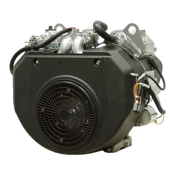
- Page 1 SERVICE MANUAL Models EH63, 64, 65 and EH72 ENGINES PUB-ES2158 Rev. 08/09...
- Page 2 Robin America, Inc. 905 Telser Road • Lake Zurich, IL 60047 • Phone: 847-540-7300 • Fax: 847-438-5012 e-mail: sales@robinamerica.com • www.subarupower.com © Copyright 2009 Robin America, Inc.
-
Page 3: Table Of Contents
CONTENTS Section Title Page 1. SPECIFICATIONS ..........1 2. -
Page 4: Specifications
1. SPECIFICATIONS MODEL EH63D EH64D EH65D EH72D Type Air-Cooled, 4-Stroke, V-Twin Cylinder, Horizontal P.T.O. shaft, OHV Gasoline Engine Bore x stroke mm (in.) 2 - 80 x 65 (3.15 x 2.56) 2 - 84 x 65 (3.31 x 2.56) Displacement (cu. -
Page 5: Maximum Output
2. PERFORMANCE 2-1 MAXIMUM OUTPUT The maximum output is the output of an engine with its throttle valve fully opened under the condition that all the moving parts are properly worn in after the initial break-in period. A new engine may not produce full maximum output while its moving parts are still not broken-in. NOTE : Power curves shown in the following charts are made in conformity to SAE internal combustion engine standard test code J1349... - Page 6 2-4 PERFORMANCE CURVES EH63D ( kgf-m ) 45 ( 4.59 ) 35 ( 3.57 ) MAXIMUM TORQUE MAXIMUM HORSEPOWER ( 20.1 ) ( HP ) CONTINUOUS ( 13.4 ) RATED HP RECOMMENDED HORSEPOWER RANGE ( 6.7 ) 2000 2400 2800 3200 3600 REVOLUTION...
- Page 7 EH64D ( kgf-m ) 45 ( 4.59 ) 35 ( 3.57 ) MAXIMUM TORQUE MAXIMUM HORSEPOWER ( 20.1 ) ( HP ) CONTINUOUS RATED HP ( 13.4 ) RECOMMENDED HORSEPOWER RANGE ( 6.7 ) 2000 2400 2800 3200 3600 REVOLUTION r.p.m –...
- Page 8 EH65D ( kgf-m ) 45 ( 4.59 ) 35 ( 3.57 ) MAXIMUM TORQUE MAXIMUM HORSEPOWER ( 20.1 ) ( HP ) CONTINUOUS RATED HP ( 13.4 ) RECOMMENDED HORSEPOWER RANGE ( 6.7 ) 2000 2400 2800 3200 3600 REVOLUTION r.p.m –...
- Page 9 EH72D ( kgf-m ) 55 ( 5.61 ) 45 ( 4.59 ) MAXIMUM TORQUE ( 26.8 ) MAXIMUM HORSEPOWER ( HP ) (20.1) CONTINUOUS RATED HP (13.4) RECOMMENDED HORSEPOWER RANGE ( 6.7 ) 2000 2400 2800 3200 3600 REVOLUTION r.p.m –...
- Page 10 3. FEATURES Highly rigid structure High-carbon steel, forged crank shaft Light-weight , tough alminum forged connectiong rod Ball-bearing Special cast iron cylinder liner Long-lasting structure Forced pressure lubrication of crankshaft by directly connected trochoid pump Standard equipped oil cooler ensures a good lubrication environment Ball bearing installed in the throttle bearing of the carbureter Reliability Unusually high dust proofing by a double compartment air cleaner and inner vent type carbureter...
-
Page 11: General Description Of Engine Components
4. GENERAL DESCRIPTION OF ENGINE COMPONENTS ROBIN EH63D/64D/65D/72D engine is air-cooled, 4-stroke, twin-cylinder, OHV arrangement gasoline engine. The twin-cylinder is located in the angle of 90 degree; #1 cylinder is in the RH side and #2 cylinder in LH side as viewed from flywheel (cooling fan) side. - Page 12 4-4 CONNECTING ROD AND PISTON The connecting rod is forged aluminum alloy, and its large and small ends function as bearings. The piston is an aluminum alloy casting, and carries two compression rings and one oil ring. 4-5 PISTON RINGS The piston rings are made of special cast iron.
- Page 13 4-7 CYLINDER HEAD The cylinder head is an aluminum die-casting which utilizes semi-spherical type combustion chamber for the high combustion efficiency. 4-8 VALVE ARRANGEMENT The intake valve is located on flywheel side of the cylinder head. The cooling fins and passages design lead cooling air to the exhaust valve area for the optimum cooling.
- Page 14 4-10 COOLING SYSTEM The large fins on the flywheel provide sufficient cooling air capacity for cylinder and cylinder head. The cylinder baffle helps the cooling air flow efficiently. 4-11 LUBRICATION SYSTEM The engine is furnished with full pressure lubrication system. The trochoid type oil pump is driven by crankshaft and delivers pressurized engine oil through the full- flow type oil filter to the journal and pin portions of...
- Page 15 4-14 CARBURETOR The engine is equipped with a down draft carburetor that has a float controlled fuel system and a fixed main jet. The carburetors are calibrated carefully for the sure FUEL CUT SOLENOID VALVE starting, low fuel consumption and sufficient output. Fuel cut solenoid valve is provided to prevent engine running on when the key switch is turned to off.
-
Page 16: Sectional View Of Engine
4-17 SECTIONAL VIEW OF ENGINE CARBURETOR INTAKE MANIFOLD IGNITION COIL P.T.O.SHAFT OIL PUMP MAIN BEARING COVER FLYWHEEL OIL PUMP FILTER – 13 –... - Page 17 AIR CLEANER CAMSHAFT GOVERNOR LEVER PUSH ROD ROCKER ARM INTAKE AND EXHAUST VALVES SPARK PLUG PISTON RING PISTON PISTON PIN TAPPET OIL COOLER (EH72D) OIL FILTER ELECTRIC STARTER CRANKCASE CRANKSHAFT CONNECTING ROD – 14 –...
-
Page 18: Preparations And Suggestions
No Special Tool is needed for disassembling and reassembling the engine. For pulling off the flywheel, universal type puller being popular in the market place as shown in the illustration is needed. Tool No. Tool 228-95001-17 Flywheel puller with bolt EH63,64,65,72 / DY30,35,41,42 FLYWHEEL PULLER – 15 –... -
Page 19: Disassembly Procedures
5-3 DISASSEMBLY PROCEDURES Step Parts to remove Remarks and procedures Fasteners Drain engine oil by removing plugs located Engine oil drain M14 x 12 Drain plug : 2 pcs. on both side of crankcase. M6 x 14 Flange bolt : 4 pcs. Muffler cover M6 x 8 Flange bolt : 2 pcs. - Page 20 Step Parts to remove Remarks and procedures Fasteners Air cleaner cover and elements Remove cleaner cover and cleaner element. Air cleaner base Remove breather pipe from #1 cylinder head. M6 x 12 Flange bolt : 3 pcs. WING NUT CLEANER COVER BREATHER PIPE STEP 5...
- Page 21 Step Parts to remove Remarks and procedures Fasteners Blower housing Disconnect fuel pipe and remove blower M6 x 18 Flange bolt : 2 pcs. Control box housing along with control box. M6 x 14 Flange bolt : 6 pcs. (1) Remove the choke knob. Chock control lever and link M6 bolt : 1 pc.
- Page 22 Step Parts to remove Remarks and procedures Fasteners Carburetor M8 x 80 Flange bolt : 2 pcs. At first remove fuel pipe. Take out carburetor along with governor rod and rod spring. M8 FLANGE BOLT CARBURETOR FUEL PIPE STEP 9 GASKET, carburetor –...
- Page 23 Step Parts to remove Remarks and procedures Fasteners Governor lever 1. Remove bolt and take out lever. M6 x 12 bolt and (Make sure the fitting location of governor washer : 3 pcs. springs.) Speed control lever M6 self-lock nut : 1 pc. 2.
- Page 24 Step Parts to remove Remarks and procedures Fasteners Remove pluse pipe at first. Remove fuel pump ASSY and detach M6 x 12 Flange bolt : 2 pcs. Fuel pump bracket. M6 x 12 Flange bolt : 2 pcs. Ignition coil (1) Take out plug cap.
- Page 25 Step Parts to remove Remarks and procedures Fasteners Intake manifold M8 flange nut : 4 pcs. Disconnect wire connector from regulator, Regulator and Wire CP M6 x 12 Flange bolt : 2 pcs. and then remove regulator from #1 cylinder baffle.
- Page 26 Step Parts to remove Remarks and procedures Fasteners Cylinder baffles M6 x 12 flange bolt : 8 pcs. (#1, #2, #3 & #4) M6 FLANGE BOLT CYLINDER BAFFLE #3 CYLINDER BAFFLE #1 CYLINDER BAFFLE #4 M6 FLANGE BOLT STEP 17 M6 FLANGE BOLT M6 FLANGE BOLT CYLINDER...
- Page 27 Step Parts to remove Remarks and procedures Fasteners Cooling fan Remove cooling fan from flywheel. M6 x 16 bolt & washer : 4 pcs. Untighten flywheel nut and leave it to Flywheel M18 Flange nut: 1 pc. avoid the flywheel fell out. Take out flywheel by means of flywheel puller.
- Page 28 Step Parts to remove Remarks and procedures Fasteners Take care the spark plug is hot just after Spark plug NGK : BPR4EY stopping engine. 1. Disconnect oil hoses with clamps detached. Oil cooler (EH72) 2. Remove oil cooler. M6 x 12 Flange bolt : 4 pcs. 3.
- Page 29 Step Parts to remove Remarks and procedures Fasteners Rocker cover Remove rocker cover along with hook. M6 x 28 Flange bolt : 8 pcs. When removing “rocker arm” and “Bolt,pivot”, M10 x 65 Flange bolt : 8 pcs. turn and adjust flywheel at TDC with the marking “T”...
- Page 30 Step Parts to remove Remarks and procedures Fasteners Intake & exhaust valves Take out collet-valves with spring retainer depressed by hand. Take out valve springs. Breather cover M6 x 14 Flange bolt : 2 pcs. Breather plate COLLET-VALVE COLLET-VALVE SPRING RETAINER SPRING RETAINER VALVE SPRING VALVE SPRING...
- Page 31 Step Parts to remove Remarks and procedures Fasteners Main bearing cover Take out key from PTO shaft. M8 x 45 Flange bolt : 10 pcs. Wrap PTO shaft with polyvinyl tape not to damage oil seal by key groove edge. Tapping with plastic hummer, take out main bearing cover.
- Page 32 Step Parts to remove Remarks and procedures Fasteners Camshaft Mate the markings both on crankshaft gear and camshaft gear and then take out camshaft. tappet Put the marking of original position onto each tappet for reassembly. CAMSHAFT TAPPET STEP 27 TAPPET CAMSHAFT –...
- Page 33 Step Parts to remove Remarks and procedures Fasteners Connecting rod (1) Remove connecting rod bolts. M8 Connecting rod bolt : 4 pcs. Take out connecting rod cap. Piston (2) Push the connecting rod upwards and take out *Piston pin clip along with piston.
- Page 34 Step Parts to remove Remarks and procedures Fasteners Crankcase (1) Disconnect wire connector from oil pressure *Oil pump switch, and remove switch. *Oil filter *Oil pressure switch (2) Remove oil filter and adapter. M6 x 28 Flange bolt : 3 pcs. *Oil pump filetr *Oil relief spring &...
-
Page 35: Reassembly Procedures
5-4 REASSEMBLY PROCEDURES 5-4-1 PRECAUTIONS FOR REASSEMBLY 1) Clean parts thoroughly before reassembly. Pay most attention to cleanliness of piston, cylinder, crankshaft, connecting rod and bearings. 2) Scrape off all carbon deposits from cylinder head, piston top and piston ring grooves. 3) Check lip of oil seals. - Page 36 B. CYLINDER HEAD, VALVES and ROCKER ARM NOTE ; * Clean valves and wash cylinder head thoroughly. * Remove carbon and gum deposits from the valves, seats, ports and guides. * Inspect valves, valve seats and valve guides. * Replace valves that are badly burned, pitted or warped. * Valve guides should be replaced when valve stem clearance exceeds specifications.
- Page 37 C. PISTON RING and CONNECTING ROD (1) PISTON and PISTON RING NOTE ; * Top ring can be fit either way. Install oil ring first, then second ring and top ring. * Install second ring with punched mark Spread ring only far enough to slip over piston and beside the gap on the top side.
- Page 38 5-4-3 Re-assembly CRANKSHAFT 1) CRANKSHAFT Install crankshaft onto crankcase. NOTE ; * Apply enough oil to bearing portion of crankcase. * For smooth fitting of crankshaft, assemble oil pump related parts later. * For easy installation, put crankcase on box or wood blocks.
- Page 39 3) TAPPET and CAMSHAFT CAMSHAFT GEAR (1) Apply oil to tappets and install in their original position. Push in fully to avoid damage during camshaft installation. (2) Lubricate bearing surfaces of camshaft. Install camshaft into the crankcase with the timing mark on both crankshaft gear and camshaft alined.
- Page 40 5) MAIN BEARING COVER (1) Put a oil seal guide onto PTO shaft portion to avoid damaging the main bearing cover oil seal. (2) Place gasket onto the mating surface of crankcase. (3) Lubricate oil seal lip portion and bearing surfaces, and install main bearing cover. Tighten bolts evenly to the specified torque.
- Page 41 8) PUSH RODS Rotate crankshaft to the position in the no lifted condition of tappet. Be sure to loose the rocker arm adjust screw. (1) Insert push rods into the concave portion of tappet and set the other end to the concave portion of rocker arm adjust screw with valve spring depressed.
- Page 42 11) BREATHER PIPE and COVER GASKET , breather plate Attach breather plate (breather valve) and BREATHER PLATE breather cover to crankcase using proper gaskets. Put breather plate in such position as its reed valve opens outside. M6 x 14 Flange bolt : 2 pcs. Tightening torque 2.9 - 4.9 N m GASKET , breather plate...
- Page 43 16) INTAKE MANIFOLD GASKET, muffler (1) Set gasket (stainless steel) onto both #1 and #2 M8 FLANGE NUT cylinder head. (2) Install intake manifold. INTAKE MANIFOLD M8 flange nut : 4 pcs. Tightening torque 16.6 - 18.6 N m M8 FLANGE (170 - 190 kgf cm) (12.3 - 13.7 ft lb.) GASKET, muffler...
- Page 44 20) IGNITION COIL and WIRE CP Temporally fit ignition coil to crankcase. THICKNESS GAUGE IGNITION COIL Adjust air gap between ignition coil and flywheel using a thickness gauge and tighten bolts. Ignition coil air gap WIRE 0.3 - 0.5 mm (0.012 - 0.020 in.) M6 x 30 bolt &...
- Page 45 22) CARBURETOR M8 FLANGEBOLT Set gasket onto intake manifold and install carburetor. CARBURETOR M8 x 80 Flange bolt : 2 pcs. Tightening Torque 16.6 - 18.6 N m (170 - 190 kgf cm) (12.3 - 13.7 ft lb.) GASKET, carburetor 23) CHOKE CONTROL LINK PIVOT Attach chock control link between carburetor...
- Page 46 GEAR GOVERNOR LEVER ROD SPRING GOVERNOR ROD FULL OPEN FULL CLOSE LOCK NUT Fitting location of governor rod and governor spring 50Hz 60Hz GOVERNOR SPRING EH63 A-3(b) A-2(b) ADJUSTING SCREW EH64 A-3(b) A-2(b) SPEED CONTROL LEVER EH65 A-3(a) A-2(a) HIGH SPEED...
- Page 47 26) ADJUST GOVERNOR SYSTEM Governor system is centrifugal flyweight type. Governor weight is installed into governor gear driven by crankshaft. Governor weight movement is transferred to carburetor throttle lever via governor shaft and lever. GOVERNOR LEVER Engine speed is maintained at the constant speed GOVERNOR SHAFT by carburetor throttle valve opening and closing operation in accordance with load condition of...
- Page 48 28) FUEL PUMP and FUEL PIPE (1) Install fuel pump bracket onto #2 cylinder baffle. FUEL PUMP BRACKET M6 x 12 Flange bolt : 2 pcs. Tightening torque 6.8 - 8.8 N m (70 - 90 kgf cm) (5.0 - 6.5 ft lb.) (2) Install fuel pump onto fuel pump bracket.
- Page 49 30) OIL PRESSURE SWITCH [EH63, 64, 65] Install oil pressure switch onto crankcase. OIL PRESSURE SWITCH [EH63, 64, 65] Install oil pressure switch onto adapter(Oil cooler). [EH72] Tightening torque 5.9 - 9.8 N m (60 - 100 kgf cm) (4.3 - 7.2 ft lb.) [EH72] NOTE ;...
- Page 50 32) FUEL PUMP PLUSE PIPE Connect fuel pipe between fuel pump and crankcase nipple. 33) MUFFLER (1) Install Muffler bracket onto Cylinder head. M6 FLANGE BOLT M8 x 20 bolt & washer : 2 pcs. Tightening torque MUFFLER COVER 16.6 - 18.6 N m (170 - 190 kgf cm) (12.3 - 13.7 ft lb.) (2) Install Muffler onto Muffler bracket and Cylinder...
-
Page 51: Break-In Operation
While the engine is being tested, check for oil leaks. Make final carburetor adjustment and regulate the engine operating speed. STEP EH63 EH64 EH65 EH72 Engine speed(rpm) -
Page 52: Lubrication System
* The by-pass valve is incorporated into the cartridge type oil filter. In case that the oil filter element is clogged, the engine oil is fed through the by-pass valve into the crankcase oil passage. [EH63, 64, 65] OIL FILTER... - Page 53 [EH72] OIL PRESSURE SWITCH OIL COOLER CAMSHAFT OIL FILTER CRANKSHAFT RELIEF VALVE OIL PUMP OIL PUMP FILTER Oil relief Valve opening pressure : 3.8 kg/cm (373KPa) puressure switch Camshaft relief journal valve Crankshaft Crankshaft Crankpin & Oil pump Element Oil pan journal journal Connecting rod...
- Page 54 ENGINE OIL Using engine oil of the correct grade and viscosity greatly lengthens engine life and improves performance. Too much or too little oil can also result in serious problems, including engine seizure. CLASSIFICATION BY OIL GRADE API (American Petroleum Institute) Classification Grades suited for Robin Engine: SE or higher (SG,SH or SJ in recomended) CLASSIFICATION BY OIL VISCOSITY...
-
Page 55: Fuel System
7. FUEL SYSTEM 7-1 FUEL PUMP Fuel suction process The inside of crankcase becomes vacuum condition in accordance with the piston moving upwards to the top dead center. The vacuum pressure, which is introduced via hose into the pulse chamber of fuel pump, pulls the diaphragm, and then the inside of pump chamber becomes vacuum condition. - Page 56 7-2. CARBURETOR OPERATION AND FUNCTION [EH63, 64, 65] CHOKE VALVE PILOT AIR JET AIR VENT HOLE MAIN AIR JET EMULSION TUBE FLOAT NEEDLE VALVE FUEL CUT VALVE FUEL INLET PIPE FUEL MAIN JET MAIN NOZZLE PILOT JET THROTTLE VALVE TAMPER CAP...
- Page 57 FLOAT SYSTEM The float system is consists of a float and a needle valve, and maintains a constant fuel level during engine operation. The fuel flows from the fuel tank into the float chamber through needle valve. When the fuel rises to a specific level, the float rises, and when its buoyancy and fuel pressure are balanced, the needle valve closes to shut off the fuel, thereby keeping the fuel at the predetermined level.
- Page 58 COMPORNENT PARTS [EH63, 64, 65] 1. BODY, lower 11. MAIN JET 2. GASKET, body upper 12. SOLENOID VALVE ASS’Y 3. BODY, upper 13. JET, slow 4. LEVER ASSY, choke 14. NEEDLE, idle adjust 5. SPRING, choke 15. THROTTLE SHAFT ASS’Y 6.
- Page 59 [EH72] 1. BODY, lower 16. SCREW, float pin set 31. SCREW and WASHER ASS'Y 2. GASKET, air horn 17. MAIN JET 32. SPRING 3. BODY, upper 18. GASKET 33. DIAPHRAGM ASS'Y 4. LEVER ASS'Y, choke 19. SOLENOID VALVE ASS'Y 34. COVER ASS'Y 5.
-
Page 60: Electric System
8. ELECTRIC SYSTEM OPERATION AND FUNCTION The ignition system is pointless flywheel magneto with automatic advancing characteristic. Being different from the breaker point type ignition system, this system is completely free from such troubles as starting-up failure owing to dirty, burnt or corroded point surface. The electronic automatic advancing ensures extremely easy starts and stable high performance at operating speed by advancing the ignition timing to the most suitable point. -
Page 61: Wiring Diagram
(3) At higher engine revolution, the advancing control circuit operates at the ignition timing to run the base current I to turn the signal transistor B "ON" allowing the current I to bypass as current I At this moment the power transistor turns "OFF" and the current I is abruptly shut resulting in the high voltage generated in the secondary coil which produces sparks at the spark plug. -
Page 62: Electric Starter
ELECTRIC STARTER When key switch is turned ON, lower electric current (M ) flows through coil of magnetic switch and the coil is excited. The plunger is pulled and higher current (S ) flows through electric starter. When electric starter is operated, pinion gear is pushed out by means of centrifugal force of weight located in the spline of armature shaft. - Page 63 SPARK PLUG CAP Spark plug cap • Check continuity with a circuit tester. • Spark plug cap has no resistor. • If there is no continuity, replace the spark plug cap. SPARK PLUG Engine body Associated cable Sparking performance a a : Over 6.0 mm (0.236 in.) Electrode gap b b : 0.7 to 0.8 mm (0.028 - 0.031 in.) •...
- Page 64 IGNITION COIL • Adjust the air gap between the ignition coil and flywheel using a thickness gauge and tighten bolts. Ignition coil air gap 0.3 - 0.5 mm (0.012 - 0.020 in.) Measure the resistance between the wires and core. Resistance High-tension cable (Secondary) Stop wire (Primary)
- Page 65 REGULATOR • Measure the resistance between the wires. Rated resistance value: (Ω ± 20% when 20˚C) Apply black (-) needle of the circuit tester Apply red (+) needle of the circuit tester • Replace the regulator if the actual resistance value differs from the rated value. OIL PRESSURE SWITCH Structure of Oil Pressure Switch (Sensor) Switching Pressure : 1.0 kg/cm2 ±...
-
Page 66: Troubleshooting
9. TROUBLESHOOTING The following three conditions must be fulfilled for satisfactory engine start. (1) The cylinder filled with a proper fuel-air mixture. (2) Good compression in the cylinder. (3) Good spark, properly timed, to ignite the mixture. The engine cannot be started unless these three conditions are met. There are also other factors which make engine start difficult, e.g., a heavy load on the engine when it is about to start at low speed, and a high back pressure due to a long exhaust pipe. -
Page 67: Starting Difficulties
9-2 STARTING DIFFICULTIES Phenomenon Possible causes Remedy 1) Battery discharged Charge battery 2) Poor connection between battery and starter motor Clean or repair 1. Low engine 3) Poor connection between battery and ground Clean or repair speed at starting 4) Electric starter faulty Repair or replace Replace with recommended 5) Improper engine oil... -
Page 68: Insufficient Output
9-3 INSUFFICIENT OUTPUT Phenomenon Possible causes Remedy 1) Loosen spark plug Retighten or replace gasket 2) Cylinder head gasket leakage Retighten or replace gasket 3) Piston ring(s) seizure or wear Replace 1. Low 4) Piston or cylinder wear Repair or replace compression 5) Incorrect valve and seat contact Repair or replace... -
Page 69: Rough Idling
9-5 ROUGH IDLING Phenomenon Possible causes Remedy 1) Low idling speed Adjust 1. Carburetor 2) Carburetor slow system passage clogged Check and clean 2. Intake system 1) Air mixing from connecting portion of air intake system Check, tighten or replace gasket 3. -
Page 70: High Fuel Consumption
9-7 HIGH FUEL CONSUMPTION Phenomenon Possible causes Remedy 1) Over-size main jet Replace 2) Needle valve faulty and/or high fuel level in float 1. Fuel system Adjust or replace chamber 3) Chock valve does not open fully. Repair or replace 1) Low compression Check or repair 2. -
Page 71: Engine Misfire
9-9 ENGINE MISFIRE Phenomenon Possible causes Remedy 1) Improper spark plug gap or damaged electrode Cealn, adjust or replace 2) Ignition coil faulty Replace 1. Ignition system 3) Damaged ignition system wirings Replace 4) Poor connection of ignition system wirings Check and connect properly 1) Lean or rich air/fuel mixture Disassembly and repair... - Page 72 10. INSTALLATION Engine life, ease of maintenance and inspection, frequency of checks and repairs, and operating cost all depend on the way in which the engine is installed. Review the following instructions carefully for installing the engine. 10-1 INSTALLING When mounting the engine, carefully examine its position, the method of connecting it to a machine, the foundation, and the method of supporting the engine.
-
Page 73: Standard Dimensions And Service Limits
If the measurement exceeds beyond the "Limit", the part needs to be replaced and/or repaired. 11-1 STANDARD DIMENSIONS AND SERVICE LIMITS Unit : mm(in.) ITEM Limit CYLINDER HEAD * Flatness EH63 EH64 0.05 or less (0.002 or less) (0.004) EH65 EH72... - Page 74 Unit : mm(in.) ITEM Limit CYLINDER EH63 To be rebored when 80.000 - 80.019 * Inside dia. EH64 (3.1496 - 3.1504) the difference between EH65 max. and min. of diameter reached to 84.000 - 84.022 EH72 0.1 (0.004). (3.3071 - 3.3080) EH63 80.250 - 80.269...
- Page 75 Unit : mm(in.) ITEM Limit PISTON EH63 * Ring groove side clearance EH64 0.05 - 0.09 0.15 EH65 (0.0002 - 0.0035) (0.006) EH72 EH63 EH64 0.03 - 0.07 0.15 EH65 (0.0012 - 0.0028) (0.006) EH72 EH63 EH64 0.057 - 0.175 0.15...
- Page 76 Unit : mm(in.) ITEM Limit CONNECTING ROD * Big end inside dia. EH63 EH64 39.000 - 39.016 39.100 (1.5354 - 1.5361) (1.5394) EH65 EH72 * Clearance between big end and crankpin EH63 EH64 0.030 - 0.060 (0.0012 - 0.0024) (0.079)
- Page 77 Unit : mm(in.) ITEM Limit CAMSHAFT * Cam height (IN. and EX.) EH63 EH64 35.35 - 35.37 35.20 EH65 (1.392 - 1.393) (1.385) EH72 * Journal outside dia. “D” type EH63 19.967 - 19.980 19.950 EH64 EH65 (0.7861 - 0.7866) (0.7854)
- Page 78 Unit : mm(in.) ITEM Limit TAPPET * Stem outside dia. EH63 EH64 8.954 - 8.979 8.924 (0.3525 - 0.3535) (0.3513) EH65 EH72 * Guide inside dia. EH63 EH64 9.00 - 9.015 9.08 (0.3543 - 0.3549) (0.3575) EH65 EH72 * Tappet guide clearance...
-
Page 79: Tightening Torque
11-2 TIGHTENING TORQUE Tightening Torque ITEMS kgf cm ft lb. Breather cover 2.9 - 4.9 30 - 50 2.2 - 3.6 Carburetor bolts 16.6 - 18.6 170 - 190 12.3 - 13.7 Charge coil 2.9 - 3.9 30 - 40 2.2 - 2.9 Connecting rod cap bolts 22 - 27... -
Page 80: Maintenance And Storage
12. MAINTENANCE AND STORAGE 12-1 DAILY MAINTENANCE Every day before operating engine, check the following items : MAINTENANCE ITEMS REMARKS 1) Clean away dust and chaff from engine. Governor linkage is especially sensetive to dust. 2) Check fuel leakage from fuel system. If any, retighten fasteners or replace necessary parts. - Page 81 Periodic Maintenance Schedule table Every Every Every Every Every 1000 8 hours 50 hours 200 hours Maintenance Items hours (Daily) (Weekly) (Monthly) hours (Daily) Clean engine and check bolts and nuts Check and refill engine oil (Refill daily up to upper level) (Initial 20 hours) Change engine oil (*Note : 1) (Every 100 hours)
- Page 82 12-3 SPARK ARRESTER (OPTIONAL) In a dry or wooded area, it is recommendable to use the product with a spark arrester. Some areas require the use of a spark arrester. Please check your local laws and regulations before operating your product. The spark arrester must be cleaned regularly to keep it functioning as designed.
- Page 83 12-4 ENGINE STORAGE (1) Change the engine oil and perform the daily maintenance items above mentioned. (2) Drain fuel from carburetor float chamber. (3) To prevent rust in the cylinder bore, apply oil through the spark plug hole and turn the crankshaft several turns by hand.
- Page 85 PRINTED IN THE USA...
Need help?
Do you have a question about the EH63 and is the answer not in the manual?
Questions and answers