Table of Contents
Troubleshooting

Subscribe to Our Youtube Channel
Related Manuals for Argo AT Series


Summary of Contents for Argo AT Series
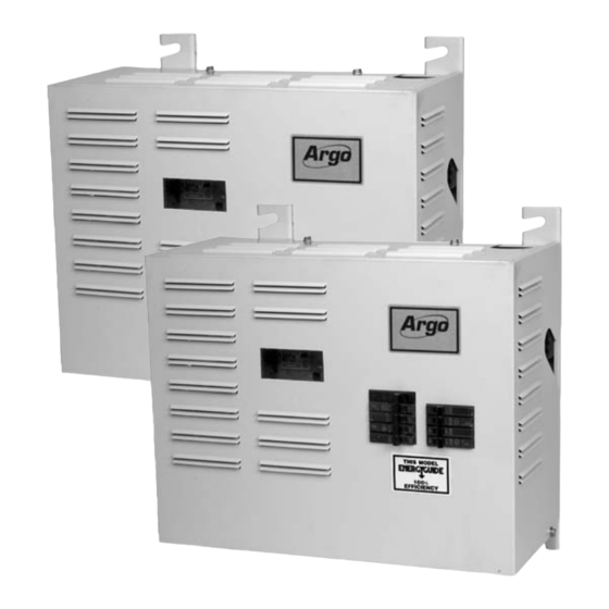
- Page 1 "AT" SERIES ELECTRIC HOT WATER BOILERS FOR FORCED HOT WATER ARGO (Technical Support) 2201 Dwyer Avenue Utica, NY 13501 (Corporate Sales) 85 Middle Road An ISO 9001-2000 Certified Company Dunkirk, NY 14048 www.argocontrols.com P/N I80, Rev. A [05/08]...
-
Page 2: Table Of Contents
INSTALLATION MANUAL AND OPERATING INSTRUCTIONS SAFETY SYMBOLS TABLE OF CONTENTS The following defined symbols are used throughout Safety Symbols ............ 2 this manual to notify the reader of potential hazards Warnings .............. 3 of varying risk levels. Introduction ............3 Product Description .......... -
Page 3: Warnings
The Hydronics Institute Argo electric boilers are designed and manufactured (I=B=R) manual H-22 (Heat Loss Calculation with quality components for maximum life and Guide), or by any other method which is suit- durability and require minimum service. -
Page 4: Voltage Rating Tables
PRODUCT DESCRIPTION continued The following important product information is located ARGO Electric Boilers are controlled by a electronic on the cabinet cover: temperature controller. The controller controls the boiler water temperature with multiple stages and • Model Number turns stages on based on the heating demand, •... -
Page 5: Installation Procedure
INSTALLATION PROCEDURE Improper installation, adjustment, alteration, service Install unit with a minimum clearance from or maintenance can cause injury or property top of unit to ceiling of 16 inches. If minimum damage. requirements of space are used, it is suggested that the enclosure be exposed to some means of 1. -
Page 6: Design Of Water Circulating System
at the bottom of the unit. Reverse flow will result DESIGN OF WATER in a noisy operation and cause very early element CIRCULATING SYSTEM failure. The drain cock is to be located at the System should be designed as primary/secondary lowest point of piping. - Page 7 PRIMARY/SECONDARY PIPING FIGURE 2 PRIMARY/SECONDARY PIPING FOR MULTIPLE zONING WITH CIRCULATORS FIGURE 3 PRIMARY/SECONDARY PIPING FOR MULTIPLE zONING WITH zONE vALvES...
-
Page 8: Connecting Electrical Power Supply
Tighten terminal screw clamps. DO NOT USE ALUMINUM WIRE!! FIGURE 4 Argo Electric Hydronic Boilers are pre-wired for use with 240-volt, 3 wire, single-phase, 50/60-hertz power. Refer to Table 1B on page 4 for the reduction in boiler capacity when the line voltage is less than 240 volts. - Page 9 ampacity and temperature. Use copper wire only CONTROL BOARD POWER CONSUMPTION: with insulation rated for 75 °C. Check state and 0.8A max. local requirements. LED DISPLAY LIGHTS (Figure 6): A total of 8 LED indicator lights display the following information: NOTE: Read the data name plate before (1) T-T (Green): LED is lit when thermostat is connecting unit so that you will become...
- Page 10 CONTROL INFORMATION continued TEMPERATURE CONTROL RANGES: energized for 3 minutes to purge the boiler. After 3 minutes the control will de-energize the circulator Temperature: Degrees Fahrenheit ("Circ" LED turns off). Operating Temperature Range: 90°F - 180°F If at any time during the start-up of the boiler or during (Factory Setting: 180°F) operation a safety end switch opens its respective contact, the control de-energizes all elements,...
-
Page 11: Wiring Diagrams
WIRING DIAGRAMS FIGURE 7A... - Page 12 WIRING DIAGRAMS FIGURE 7B...
- Page 13 WIRING DIAGRAMS FIGURE 8A...
- Page 14 WIRING DIAGRAMS FIGURE 8B...
-
Page 15: Thermostat Installation
3. Do not install a thermostat where it will be affected by sunlight, drafts, televisions, lighting fixtures, hot or cold pipes, fireplaces, or chimneys. NOTE: Your new Argo AT Boiler will work well with all standard and most programmable set- back thermostats. -
Page 16: Troubleshooting
6. Check system again for leaks. Allow circulator 8. When the thermostat calls for heat, the circulator pump to run until all air has been vented from the will be energized and the indicator LED will light system. A gurgling or rushing sound indicates the up. -
Page 17: Maintenance
1. Turn off hydronic unit circuit breaker at service entrance and/or disconnect switch. MAINTENANCE the pressure relief valve by pulling the lever at the Because of its basic design, the hydronic block re- end of the valve until the lever is in line with the quires only a minimum of periodic maintenance. -
Page 18: Parts List - 2 Element Electric Boilers
PARTS LIST - 2 ELEMENT ELECTRIC BOILERS 2 ELEMENT BOILER (Side view) 2 ELEMENT BOILER 2 ELEMENT BOILER With Power Block With Breakers 2 Element Electric Boiler w/Breakers 2 Element Electric Boiler w/Power Block Part Part Num- Item Description Item Description Number Safety Limit Control (High Limit - Fixed Temp) -
Page 19: Parts List - 4 Element Electric Boilers
PARTS LIST - 4 ELEMENT ELECTRIC BOILERS 4 ELEMENT BOILER (Side view) 4 ELEMENT BOILER 4 ELEMENT BOILER With Power Block With Breakers 4 Element Electric Boiler w/Power Block 4 Element Electric Boiler w/Breakers Part Part Item Description Item Description Number Number Safety Limit Control (High Limit - Fixed Temp) -
Page 20: Additional Wiring Diagrams
ISOLATION Relay Base, DIN Rail RELAY 240004745 Mount DIN Rail Approximatly 240004746 2" Long NOTE: NUMBERS REFER TO NUMBER DESIGNATIONS ON RELAY BASE, SEE BELOW. ARGO AR822-2II FACTORY INSTALLED JUMPER 120VAC CIR. SECONDARY CIRCULATOR RELAY PUMP 120 VAC RELAY BASE DIN RAIL "AT"... - Page 21 TWO ZONES WITH CIRCULATORS 2 BOILERS ZONE 1 ZONE 2 THERMOSTAT SPST (2 WIRE) 24 VAC TR TW TR TW ZONE 1 ZONE 2 ARGO THERMOSTATS ARM-2P ISOLATED SWITCH ZONE 1 ZONE 2 X1 X1 X2 X2 120 VAC CIR.
- Page 22 ADDITIONAL WIRING DIAGRAMS THREE ZONES WITH CONTROL VALVES ZONE 1 ZONE 2 ZONE 3 THERMOSTAT SPST (2 WIRE) ZONE 1 ZONE 2 ZONE 3 ARGO THERMOSTATS AZ-3 SWITCH ZONE 1 ZONE 2 ZONE 3 ZONE ZONE ZONE VALVE VALVE VALVE "AT"...
-
Page 23: Modular Boiler Piping
MODULAR BOILER PIPING... -
Page 24: Troubleshooting
TROUBLESHOOTING - FLOWCHART#1 WARNING Due to exposure to potentially dangerous voltages, troubleshooting should be performed by a qualified installer or service agency only. Failure to do so could result in property damage, personal injury, or loss of life. Yes (see Flowchart #3) Green T-T indicator LED is Is audible alarm sounding and red fault LED flashing? - Page 25 TROUBLESHOOTING - FLOWCHART#2 No (From Flowchart#1) Verify power Verify 120vac Is the circulator indicator supply to power to LED on? system. Board L-N. Verify that circulator is Replace the boiler control Verify that 120vac is present operating properly. board. at the circulator terminals. Verify circulator wiring or replace circulator.
- Page 26 TROUBLESHOOTING - FLOWCHART#3...
-
Page 27: At" Series Boiler Dimensions
TROUBLESHOOTING - FLOWCHART#4 OK (From Flowchart#3) Remove jumper from Does visual/audible alarm LWC-LWC and replace shut off with jumper in- stalled? LWC-LWC leads. Check water supply and Remove leads from flow-flow and test with a water level in system. Fill system if low. -
Page 28: Homeowner's Reference Table
HOMEOWNER'S REFERENCE TABLE Model Number: _____________________________________________ Serial Number: ______________________________________________ Date Installed: ______________________________________________ Contractor: _________________________________________________ Contact: ___________________________________________________ Address: ___________________________________________________ ___________________________________________________________ Telephone Number: __________________________________________ After Hours Number: _________________________________________ If different from Installation Contractor: Service Tech: _______________________________________________ Telephone Number: __________________________________________ After Hours Number: _________________________________________ www.argocontrols.com...
Need help?
Do you have a question about the AT Series and is the answer not in the manual?
Questions and answers