Argo AT0623 Installation, Operation & Maintenance Manual
"at" series electric hot water boilers for forced hot water
Hide thumbs
Also See for AT0623:
- Installation manual and operating instructions (28 pages) ,
- Installation, operation & maintenance manual (28 pages)
Table of Contents
Advertisement
An ISO 9001-2008 Certified Company
Manufactured by:
ECR International, Inc.
2201 Dwyer Avenue, Utica NY 13501
web site: www.ecrinternational.com
"AT" SERIES ELECTRIC
HOT WATER BOILERS
FOR FORCED HOT WATER
INSTALLATION, OPERATION
& MAINTENANCE MANUAL
Information and specifications outlined in this manual in effect at the
time of printing of this manual. ECR International, Inc. reserves the
right to discontinue, change specifications or system design at any
time without notice and without incurring any obligation, whatsoever.
P/N# 240009740, Rev. A [09/2013]
Advertisement
Table of Contents

Subscribe to Our Youtube Channel
Related Manuals for Argo AT0623


Summary of Contents for Argo AT0623
- Page 1 "AT" SERIES ELECTRIC HOT WATER BOILERS FOR FORCED HOT WATER INSTALLATION, OPERATION & MAINTENANCE MANUAL An ISO 9001-2008 Certified Company Information and specifications outlined in this manual in effect at the time of printing of this manual. ECR International, Inc. reserves the right to discontinue, change specifications or system design at any Manufactured by: time without notice and without incurring any obligation, whatsoever.
-
Page 2: Table Of Contents
TABLE OF CONTENTS "AT" Series Boiler Dimensions ................3 Important Safety Information ................4 Introduction ......................5 Voltage Rating Tables ..................6 Locating The Boiler ....................7 Hydronic Piping ....................8 Electrical Connections ..................10 Sequence Of Operation ..................13 Control Operation .................... -
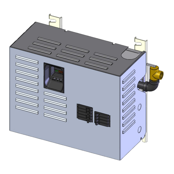
Page 3: At" Series Boiler Dimensions
"AT" SERIES BOILER DIMENSIONS Dimensions Inlet & Approximate Outlet Pipe Shipping Wt. Size 14⅝” 18⅝ “ 9¹/₃₂” 14⅜” 16¹⁵/₃₂” 1¼ NPT 70 lbs. -
Page 4: Important Safety Information
IMPORTANT SAFETY INFORMATION General Installation shall conform to requirements of authority having jurisdiction or in absence of such Boiler installation shall be completed by qualified agency. requirements: • United States WARNING • National Electrical Code, NFPA 70. Fire, explosion, asphyxiation and electrical shock •... -
Page 5: Introduction
• Dry fire protection • Clearance • Connections for flow sensor and low water cutoff • Load management control connection with auxiliary • Argo Electric Boilers are controlled by electronic control heat source connection board maintaining water temperature. Control cycles • Freeze protection heating elements based on heating demand, and •... -
Page 6: Voltage Rating Tables
Number Accessory Total Model Nominal Power Power Amperage (Watts) (140ºF) (167ºF) (194ºF) (AC) Elements Load (A) Amps (Watts) BTU/Hr. 240Vac AT0623 6,000 20,500 25.0 3,000 31.0 38.8 40.0 AT0824 8,000 27,300 33.3 4,000 39.3 49.2 50.0 AT1025 10,000 34,100 41.7 5,000 47.7... -
Page 7: Locating The Boiler
LOCATING THE BOILER WARNING Minimum clearances to combustible constructions Electrical shock hazard. Do not install boiler under are: water source. Failure to do so could result in death or serious injury. TOP ............16 IN. FRONT ............12 IN. Boiler is intended for indoor installation only and not LEFT SIDE.......... -
Page 8: Hydronic Piping
HYDRONIC PIPING Outlet or supply pipe line to radiation is located at top WARNING of unit. Combination temperature pressure (altitude) Fire, explosion, asphyxiation, burn, scald and gauge is provided with each unit and should be electrical shock hazard. System design must installed close to boiler outlet. - Page 9 HYDRONIC PIPING Figure 2 - Primary/Secondary Piping for Multiple Zoning with Circulators Figure 3 - Primary/Secondary Piping For Multiple Zoning With Zone Valves...
-
Page 10: Electrical Connections
Boiler is not designed for use of aluminum wiring. Entrance Boiler failure can occur if aluminum wiring is used. Argo Electric Hydronic Boilers are pre-wired for use with 240-volt, 3 wire, single-phase, 50/60-hertz power. For reduction in boiler capacity when line voltage is less than 240 volts see Table 1 page 6. -
Page 11: Thermostat Installation
ELECTRICAL CONNECTIONS Field Wiring - Continued Note: Argo AT Boiler will work with standard and programmable setback thermostats. Limit Control Operation Thermostat Installation MAIN POWER SUPPLY: Depending on model Install thermostat on inside wall five feet above floor. designation, the electric Hydronic Block may be NEVER install thermostat on outside wall. - Page 12 ELECTRICAL CONNECTIONS Figure 7 - Wiring on Control Board Figure 8 - Low Voltage Wiring on Control Board ELEMENTS R (T) ÉLÉMENTS W (T) Low Volt Connections DEMAND PUMP R (T) DEMANDE POMPE T Aux W (T) T Aux CONTROL BOARD T Aux CIRCUIT DU TABLEAU...
-
Page 13: Sequence Of Operation
SEQUENCE OF OPERATION Figure 8A - AT Boiler Controller HEATING ELEMENTS HEATING ELEMENT LED INDICATORS (GREEN) HEATING DEMAND LED INDICATOR DEMAND PUMP PUMP (GREEN) LED INDICATOR (GREEN) LED DISPLAY (RED) MODE AND POWER SELECTION BUTTON MODE/PWR UP DOWN UP AND DOWN ADJUSTMENT BUTTONS Figure 1 AT Boiler Controller... - Page 14 SEQUENCE OF OPERATION Setting the AT Boiler Controller User Settings Display Possible Factory Overview Value Setting On/Off Mode Press and hold the MODE/PWR button for 2 seconds to turn the unit On or Off. Note: When electrical power has been removed and re-applied, when the unit is turned on it will automatically enter a dry fire test mode (If dFt is on, see Configuration).
-
Page 15: Display Description
SEQUENCE OF OPERATION Boiler Display Codes Display Description Range Note Boiler in On mode Boiler in Off mode Comfort Heating Setting 90-180°F (32-82°C) Control prevents setting from being higher than Domestic Hot Water Setting Domestic Hot Water Setting 90-180°F (32-82°C) Control prevents setting from being lower than Comfort Heating Setting Differential Setting... -
Page 16: Control Operation
CONTROL OPERATION Initial Start Up During heating operation the safety circuit is monitored. If no faults exist the first element will energize and rate of When electrical power is applied to AT boiler the control water temperature rise is calculated. displays firmware revision code. - Page 17 CONTROL OPERATION Once initiated, Dry Fire Test can be canceled by pressing To connect a flow sensor first remove the factory installed ▲up and ▼down arrow buttons simultaneously for 2 jumper from the FLO terminals of the AT boiler control. seconds.
- Page 18 CONTROL OPERATION Boiler Fault Codes • High Limit Alarm • Freeze Protection The high limit alarm shall be monitored at all times except while the LMC terminals are open. If the water temperature falls below 45°F (7°C) the If the High Limit switch opens the control shall switch control will automatically initiate a heat call sequence off all elements and enter a 60 second purge mode.
-
Page 19: Wiring Diagrams
WIRING DIAGRAMS Figure 9 - Wiring Diagram 2 Element w/ Breakers... - Page 20 WIRING DIAGRAMS Figure 10 - Wiring Diagram 4 Element w/ Breakers...
-
Page 21: Startup And Seasonal Maintenance
STARTUP AND SEASONAL MAINTENANCE Use qualified service agency for annual inspection of When thermostat calls for heat, circulator will be boiler and heating system. energized and green pump LED will light. Heating elements are energized with green heating element LEDs. Once boiler water temperature reaches set point NOTICE temperature controller will regulate water temperature Label all wires prior to disconnection when servicing... -
Page 22: General Maintenance
GENERAL MAINTENANCE Hydronic block requires minimum periodic maintenance. Annual maintenance allow for trouble free operation. WARNING Electrical shock hazard. Turn OFF electrical power supply at main power switch before servicing unit. Service shall be preformed by a qualified service agent. Failure to do so could result in death or serious injury. -
Page 23: Additional Wiring Diagrams
ADDITIONAL WIRING DIAGRAMS Figure 11 - Single Zone with Circulator - 2 Boilers ISOLATION RELAY 1/16 HSP MAX ITEM DESCRIPTION NUMBER R35C Relay 10A 24VAC Relay Base, DIN Rail 240004745 Mount DIN Rail Approx. 2" 240004746 Long R(T) R(T) W(T) W(T) 1/6 hp MAX. - Page 24 TWO ZONES WITH CIRCULATORS 2 BOILERS ZONE 1 ZONE 2 THERMOSTAT SPST (2 WIRE) 24 VAC TR TW TR TW ZONE 1 ZONE 2 ARGO THERMOSTATS ARM-2P ISOLATED SWITCH ZONE 1 ZONE 2 X1 X1 X2 X2 120 VAC CIR.
- Page 25 - Three Zones Control Valves THREE ZONES WITH CONTROL VALVES ZONE 1 ZONE 2 ZONE 3 THERMOSTAT SPST (2 WIRE) ZONE 1 ZONE 2 ZONE 3 ARGO THERMOSTATS AZ-3 SWITCH ZONE 1 ZONE 2 ZONE 3 ZONE ZONE ZONE VALVE...
-
Page 26: Modular Boiler Piping
MODULAR BOILER PIPING... -
Page 27: Troubleshooting
TROUBLESHOOTING This section is to assist service technician when trouble After element has been removed, carefully clean any shooting electric boiler. It is important to isolate before remaining gasket material from casting surface. Take proceeding. Control error codes can be helpful identifying care not to scratch or score surface. -
Page 28: Corrective Action
TROUBLESHOOTING WARNING Electrical shock hazard. Turn OFF electrical power supply at main power switch before servicing unit. Service shall be preformed by a qualified service agent. Failure to do so could result in death or serious injury. AT Boiler Trouble Shooting Fault Possible Cause Corrective action... - Page 29 TROUBLESHOOTING N - Check control board jumper is in place and secure. Tighten FLO screws if needed. Y - System air locked - Purge system and add venting Is flow switch installed? as needed. Flow Switch Alarm Y - Check that flow switch is functioning properly. Conduct self test on flow switch (Consult manufactures instructions).
-
Page 30: Resistance Vs. Temperature Table
RESISTANCE VS. TEMPERATURE TABLE Resistance Vs. Temperature Table Temp Temp Ohms (Ω) (°C) (°F) 32.0 32,650 41.0 25,392 50.0 19,901 59.0 15,712 68.0 12,493 77.0 10,000 86.0 8,057 95.0 6,531 104.0 5,326 113.0 4,368 122.0 3,602 131.0 2,986 140.0 2,488 149.0 2,083 158.0... - Page 31 This Page Intentionally Left Blank...
-
Page 32: Parts List - 2 & 4 Element Boiler
PARTS LIST - 2 & 4 ELEMENT BOILER... - Page 33 PARTS LIST - 2 & 4 ELEMENT BOILER 2 & 4 Element Electric Boiler Item Part Number Description Relief Valve - 30 PSI Elbow 3/4" x 90° Nipple 3/4" x 2" Circuit Breaker 15 A - 1 Pole - G.E. THQP 115 Circuit Breaker 40 A - 2 Pole - G.E.
- Page 34 NOTES...
-
Page 36: Homeowner's Reference Table
HOMEOWNER'S REFERENCE TABLE Model Number: _____________________________________________ Serial Number: ______________________________________________ Date Installed: ______________________________________________ Contractor: _________________________________________________ Contact: ___________________________________________________ Address: ___________________________________________________ ___________________________________________________________ Telephone Number: __________________________________________ After Hours Number: _________________________________________ If different from Installation Contractor: Service Tech: _______________________________________________ Telephone Number: __________________________________________ After Hours Number: _________________________________________ ECR International Inc.
Need help?
Do you have a question about the AT0623 and is the answer not in the manual?
Questions and answers