
Related Manuals for Pro Audio PMA-2222


Summary of Contents for Pro Audio PMA-2222
- Page 1 PMA AMPLIFIER SERIES PROGRAMMABLE MODULAR AMPLIFIER INSTALLATION AND PROGRAMMING GUIDE PMA-2222 PMA-4242 PMA-4444 PMA-9900 PMA-9922 PMA-9942 PMA-9944 PMA-9999 PMA Installation Guide Rev A...
-
Page 2: Table Of Contents
PMA AMPLIFIER SERIES CONTENTS IMPORTANT SAFETY INSTRUCTIONS WELCOME MODEL NUMBERS POWER APPLICATIONS RACK MOUNTING HARDWARE FEATURES: FRONT PANEL 1 - LCD DISPLAY 2 - POWER LED REAR PANEL 1 - POWER AND STATUS AREA 2 - PROGRAMMING AND CONTORL AREA 3 - INPUT/OUTPUT AREA SOFTWARE FEATURES PMA MANAGER MAIN SCREEN... - Page 3 PMA AMPLIFIER SERIES AMPLIFIER PROGRAMMING PROGRAMMING OVERVIEW CONCEPTS TO KNOW PROGRAMMING STEPS STEP 1 : MAKE A PLAN STEP 2 : CONNECT AMPLIFIER TO COMPUTER STEP 3 : POWER ON AMPLIFIER STEP 4 : RUN PMA MANAGER SOFTWARE STEP 5 : SET DSP PARAMETERS FOR EACH AMPLIFER CHANNEL STEP 6 : STORE DSP PARAMETERS IN AMPLIFIER MEMORY TROUBLESHOOTING SPECIFICATIONS...
-
Page 4: Important Safety Instructions
PMA AMPLIFIER SERIES IMPORTANT SAFETY INSTRUCTIONS Read all instructions. Keep these instructions. Heed all warnings. Follow all instructions. Do not use this apparatus near water. To prevent fire or shock, do not expose this equipment to moisture or water. Clean only with a dry cloth. Do not block any ventilation openings. -
Page 5: Welcome
PMA AMPLIFIER SERIES WELCOME The PMA series amplifiers represent the second generation amplifiers from Pro Audio Technology and were developed with a single primary goal: to make installing, configuring and optimizing your PRO audio system straight forward and as painless as possible. -
Page 6: Rack Mounting
PMA AMPLIFIER SERIES PLACE A 1U SPACER BETWEEN AMPLIFIERS AND OTHER COMPONENTS IN THE RACK PMA AMPLIFIERS WITH 1U RACK SPACER RACK MOUNTING The PMA series amplifiers ship from the factory with rack mount ears installed and are ready to be placed into any industry-standard 19”... -
Page 7: Hardware Features: Front Panel
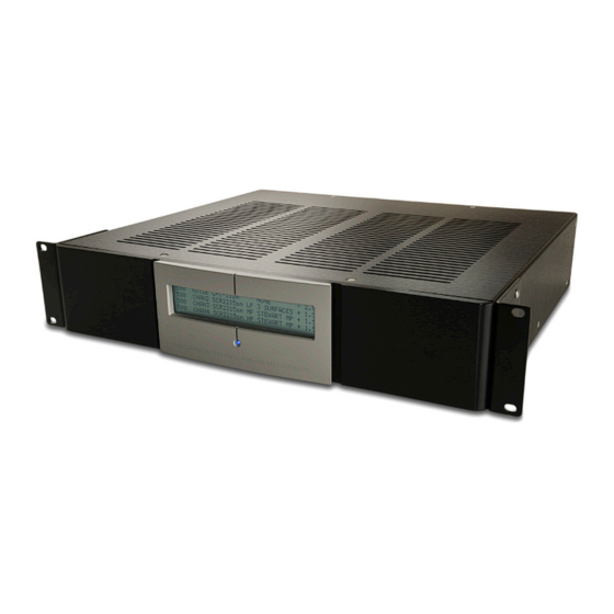
PMA AMPLIFIER SERIES HARDWARE FEATURES: 1 - LCD DISPLAY 2 - POWER LED PMA FRONT PANEL FRONT PANEL 1 - LCD DISPLAY The display will illuminate and text will appear when the amplifier main power is turned on. At start up, the display will temporarily display the amp model and serial number along with firmware ver- sion currently installed in the amplifier. - Page 8 PMA AMPLIFIER SERIES 1.1 - INSTALLED POWER 1.3 - SIGNAL ROUTING 1.4 - SPEAKER PROGRAM CHANNEL 1 CHANNEL 2 CHANNEL 3 CHANNEL 4 1.2 - CHANNEL MODIFIED 1.5 - COMPENSATION 1.6 - CHANNEL GAIN INDICATORS FILTER LCD DISPLAY 1.1 - INSTALLED POWER The first display column indicates the installed amplifier power in Watts into 4-ohms.
-
Page 9: Power Led
PMA AMPLIFIER SERIES 1.4 - SPEAKER PROGRAM Column three of the display indicates the speaker program that is installed (as set up in PMA Manager control software, see “Amplifier Programming”) for the channel. From the factory, the amplifier is pre-programmed with no speaker program and this column will display “NONE”. 1.5 - COMPENSATION FILTER The forth column indicates any acoustic compesation filter installed (as set up in PMA Manager control software, see “Amplifier Programming”) for the channel. -
Page 10: Rear Panel
CLIP SIGNAL SIGNAL WARNING: SHOCK HAZARD . DO NOT OPEN. NO USER-SERVICEABLE PARTS INSID ED ESIGNED AND ASSEMBLED IN HUNTINGT ON BEACH, CA BY PRO AUDIO TECHNOLOGY 2 - PROGRAMMING AND CONTROL PMA REAR PANEL REAR PANEL With the expception of the Power LED and LCD display, all other features of the PMA amplfiers can be found on the amp rear panel. -
Page 11: Power And Status Area
CLIP SWITCH PROGRAMMED WITH CORRECT LOUDSPEAKER PROGRAM BEFORE DEFEAT OPERATION. FAILURE TO DO SO WILL SIGNAL RESULT IN LOUDSPEAKER DAMAGE. PRO AUDIO TECHNOLOGY “PMA MANAGER” SOFTWARE REQUIED. INPU T LOOP TRIGGER SHORT OR 0V : STANDBY OPEN OR +12 V: OPERATE 1.4 - AC INLET... -
Page 12: Programming And Contorl Area
ALL INSTALLED CHANNELS MUST BE CLIP PROGRAMMED WITH CORRECT LOUDSPEAKER PROGRAM BEFORE OPERATION. FAILURE TO DO SO WILL SIGNAL RESULT IN LOUDSPEAKER DAMAGE. PRO AUDIO TECHNOLOGY “PMA MANAGER” SOFTWARE REQUIED. CHANNEL 2 TRIGGER INPU T LOOP OUTPU T SHORT OR 0V :... -
Page 13: Input/Output Area
ALL INSTALLED CHANNELS MUST BE CLIP CLIP PROGRAMMED WITH CORRECT LOUDSPEAKER PROGRAM BEFORE OPERATION. FAILURE TO DO SO WILL SIGNAL SIGN RESULT IN LOUDSPEAKER DAMAGE. PRO AUDIO TECHNOLOGY “PMA MANAGER” SOFTWARE REQUIED. CHANNEL 2 TRIGGER INPU T LOOP OUTPU T INPU T LOOP... - Page 14 PMA AMPLIFIER SERIES 3.3 CHANNEL STATUS INDICATORS PROGRAM (RED) This LED will illuminate when a valid PRO loudspeaker program has been installed into the PMA DSP for this channel. If this LED is not illuminated, that means no program is installed and audio will not pass on this channel.
-
Page 15: Software Features
PMA AMPLIFIER SERIES SOFTWARE FEATURES 3 - INFORMATION PANE 1 - TITLE BAR 2 - MAIN MENU 6 - STATUS BAR 4 - DSP CONTROL PANEL 5- UPDATE MEMORY BUTTON PMA MANAGER USER INTERFACE SOFTWARE FEATURES... -
Page 16: Pma Manager Main Screen
PMA AMPLIFIER SERIES PMA MANAGER MAIN SCREEN 1.1 - PMA SOFTWARE VERSION NUMBER 1.2 - CONNECTION STATUS PMA MANAGER TITLE BAR 1 - TITLE BAR In the top-most section of the user interface, known as the “Title Bar”, PMA Manager will display information about the software and the connection to the amplifier hardware. -
Page 17: Main Menu
PMA AMPLIFIER SERIES 2 - MAIN MENU 2.1 - FILE The file menu contains menu commands related to amplifier connections and file manage- ment. 2.1.1 Connect Select this menu item to connect to a new PMA amplifier while the software is running but is not connected to an amplifier. -
Page 18: Information Pane
PMA AMPLIFIER SERIES 2.3 - HELP The Help menu contains commands related to user help and information. 2.3.1 User Manual Selecting this option will load and display this manual in PDF format on your computer screen for reference while running the software. 2.3.2 Technical Support Brings up a form with information about how contact PRO Technical Support engineers. -
Page 19: Dsp Control Panel
PMA AMPLIFIER SERIES 4.5 - ROUTING DROP DOWN LIST CONTROL 4.4 - MUTE ON/OFF BUTTONS 4.3 - PINK NOISE 4.6 - SPEAKER PROGRAM DROP ON/OFF BUTTON DOWN LIST CONTROL 4.2 - INSTALLED POWER 4.7 - COMPENSATION FILTER DROP DOWN LIST CONTROL 4.1 - CHANNEL DESIGNATOR PMA MANAGER DSP CONTROL PANEL 4 - DSP CONTROL PANEL... - Page 20 4.6 - Channel Loudspeaker Program Drop Down List Controls This drop down list control allows you to install the loudspeaker-specific DSP programs required to operate all Pro Audio Technology loudspeaker systems. This includes both multi-amp (bi and tri-amp) as well as passive crossover models.
- Page 21 PMA AMPLIFIER SERIES 4.8 - CHANNEL LEVEL CONTROLS PMA MANAGER GUI WITH ADVANCED CONTROLS ENABLED CHANNEL DESIGNATOR LEVEL READOUT TEXT ENTRY FIELD SLIDE CONTROL RANGE CLOSE FORM BUTTON PMA MANAGER VOLUME CONTROL FORM SOFTWARE FEATURES...
-
Page 22: Update Amplifier Memory Button
PMA AMPLIFIER SERIES 4.8 - Channel Level Controls (only visible when “Advanced Controls” are activated). To adjust the gain of an amp channel left-click on the button under the Level heading in the GUI. This will open up a new window, or form, with a volume slider and text entry field. To execute an adjustment, left-click-and-hold on the slider (virtual sliding volume control) and drag up or down to the desired setting. -
Page 23: Compensation Filters
“loading” by removing the energy that would normally not be forced by the room surfaces into the direct response. These specialized filters have been designed by Pro Audio Technology using a thoughtful combi- nation of laboratory measurements and sophisticated computer models to accurately equalize for each of the conditions below. -
Page 24: Cloth Compensation
PMA AMPLIFIER SERIES Each filter is named for the brand and material for which it is designed. Simply pick the filter that matches the material of your screen and PMA Manager will install a filter which will bring the PRO speaker response back to the factory standard. - Page 25 PMA AMPLIFIER SERIES side 1 SURFACE LOADING In this case, the speaker is suf- ficiently far away enough (4’ or greater) from room side wall and floor to be considered “1 Surface” floor loading. = 4’ min side = 4’ min floor “1 SURFACE”...
-
Page 26: High And Low Pass Filters
PMA AMPLIFIER SERIES 3 SURFACE LOADING In this case, the speaker is close to two adjacent surfaces: the side side wall and the floor. Try to avoid positions like this whenever possible floor = 0’ - 4’ side = 0’ - 4’ floor 3 SURFACE LOADING - USE “3-SURFACES”... -
Page 27: Amplifier Hookup Examples
PMA AMPLIFIER SERIES AMPLIFIER HOOKUP EXAMPLES Pro Audio Technology loudspeakers are designed and built to professional audio criteria. As such, their operation differs from typical ‘consumer’ grade speakers. Namely, most PRO speakers are bi, tri or even quad-amplifer designs. This means that a separate amplifier channel is required for each transducer (loudspeaker driver) in the loudspeaker. -
Page 28: Three-Way Tri-Amp "Center Channel" Hookup Example
SIGNAL SIGNAL WARNING: SHOCK HAZARD . DO NOT OPEN. NO USER-SERVICEABLE PARTS INSID ED ESIGNED AND ASSEMBLED IN HUNTINGT ON BEACH, CA BY PRO AUDIO TECHNOLOGY No input is required at X because AMPLIFIER MODEL : PMA-4242 we’ve programmed the amplifier TO LOUDSPEAKER Channels 2 and 3 to “listen to”... -
Page 29: Amplifier Programming
To qualify to purchase and install PMA Amplifers you must first complete PRO Training Full Program. If you have not yet completed this course, do not attempt to program the amplifiers yourself. Please contact Pro Audio Technology at 1-800-272-6085 (outside the U.S. : 1-714-890-0418) to arrange train- ing. -
Page 30: Concepts To Know
PMA AMPLIFIER SERIES READ THIS SECTION CONCEPTS TO KNOW UNDERSTANGING THE RELATIONSHIP BETWEEN, AND THE ROLES OF, PMA AMPLIFIER DSP CHIP, PMA AMPLIFIER MEMORY, AND PMA MANAGER SOFTWARE If you read nothing else in this manual, READ THIS SECTION. That said, however, if you do indeed read nothing else in this manual other than this section, you run the likely risk of being summarily terminated as an Authorized PRO Dealer by PRO Dealer Authorization Ninjas. - Page 31 PMA AMPLIFIER SERIES CONCEPT TO KNOW #4: When PMA Manager sofware is communicating to a connected PMA amplfier, any changes made to the controls within the software are loaded into the amplifier DSP chip in real time and chang- es will be heard through the connected loudspeakers. At this point, however, these settings exist only in the running DSP chip - they are not yet stored in amp memory, nor on your PC.
-
Page 32: Programming Steps
PMA AMPLIFIER SERIES PROGRAMMING STEPS STEP 1 : MAKE A PLAN Identify and take inventory of amplifier models and installed powers as this information will deter- mine which program is installed into which amplifiers and on which channels. A detailed list of amp channels with corresponding target loudspeaker drivers systems should be generated from the sys- tem design. -
Page 33: Step 4 : Run Pma Manager Software
PMA AMPLIFIER SERIES STEP 4 : RUN PMA MANAGER SOFTWARE PMA MANAGER SPLASH SCREEN Once communication between the computer and amplifier has been established (you may see a “your hardware is fully installed and is ready to use” message from Windows when this happens), run the PMA Manager Software by selecting START ->... -
Page 34: Step 5 : Set Dsp Parameters For Each Amplifer Channel
PMA AMPLIFIER SERIES If PMA Manager has successfully established communication with the amplifier, it will display “CON- NECTED” in the program title bar and will list the amplifier model, serial number and installed firm- ware version in the Information Pane of the GUI (to the left of the amplifier image). If connection could not be established, “DISCONNECTED”... - Page 35 These filters are designed by Pro Audio Technology engineers to precisely compensate for the particular acoustic condition. No knowledge of science, acoustics or engineering is required to use them.
-
Page 36: Step 6 : Store Dsp Parameters In Amplifier Memory
PMA AMPLIFIER SERIES Once the desired setting has been entered and confirmed, close the gain slider control by left- clicking on the CLOSE button at the bottom of the form. CAUTION: IT IS NOT RECOMMENDED TO ADJUST THE GAIN SETTINGS OF AMP CHANNELS CONNECTED TO DRIVERS WITHIN A MULTI-WAY SPEAKER SYSTEM RELATIVE TO ONE AN- OTHER. -
Page 37: Troubleshooting
PMA AMPLIFIER SERIES TROUBLESHOOTING PROBLEM: THE SIGNAL LED INDICATES THAT SIGNAL IS GETTING TO THE AMPLIFIER CHANNEL, BUT NO SOUND IS HEARD. CAUSE 1: AMP CHANNEL IS MUTED Make sure the amp channel was not muted in by software control. Inspect the amplifier front panel display for the channel in question and observe the second column text for channel routing;... - Page 38 PMA AMPLIFIER SERIES REMEDY: Inspect the PROGRAM LED on the amp rear panel for the channel in question to determine if a valid speaker program is loaded into the DSP for the channel in question. If a valid speaker program is loaded, the PROGRAM LED will be illuminated. This LED will be off, otherwise. Alternatively, you can inspect the software GUI (when connected to the PMA amp), or the front panel display to determine the name of the speaker program installed into the DSP on the channel in question.
- Page 39 PMA AMPLIFIER SERIES TECT LED. If it comes on immediately, a fault has occurred within the amp and it will need to be returned to the factory for repair. If the LED does not come on, the amp should operate normally.
-
Page 40: Specifications
PMA AMPLIFIER SERIES SPECIFICATIONS Specification 2222 4242 4444 9900 9922 9942 9944 9999 Power Ch 1, 4 ohms 200W 450W 450W 1000W 1000W 1000W 1000W 1000W Power Ch 2, 4 ohms 200W 200W 450W 1000W 1000W 1000W 1000W 1000W Power Ch 3, 4 ohms 200W 450W 450W... -
Page 41: Warranty
PMA AMPLIFIER SERIES WARRANTY Disclaimer : Professional Home Cinema, LLC (dba “Pro Audio Technology”) is not liable for any damage to loudspeakers or any other equipment that is caused by negligence or improper use or installation of this product. Professional Home Cinema, LLC 3-Year Limited Warranty Professional Home Cinema, LLC dba “Pro Audio Technology”...
Need help?
Do you have a question about the PMA-2222 and is the answer not in the manual?
Questions and answers