Table of Contents

Related Manuals for Muskoka Mumford


Summary of Contents for Muskoka Mumford
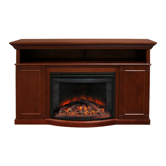
- Page 1 MEDIA CONSOLE CONSOLA DE MEDIOS CONSOLE MÉDIA Save these instructions | Conserver ces instructions | Guarde estas instrucciones MUMFORD Français p. 9 MTVSC2594SCH Español p. 16 REV05-09-13...
-
Page 2: Care And Maintenance
assEmbly tiPs before you begin, locate the instructions and hardware. Take out all the parts and compare them to the diagrams below. be sure you have all the parts and can identify them. Two people are required to assemble this product. Assembly time will take approximately 30-90 minutes. carE anD maintEnancE 1. - Page 3 assEmbly before assembly, use scissors to unwrap the parts from the packaging. DO NOT use a box cutter or exacto-knife as you may cut into the mantel pieces inside the box and damage the finish. Check for the FIG 1 hardware bag which is RED and located inside the packaging, taped to the top box.
-
Page 4: Table Of Contents
FIG 3 3. Insert and tighten 8 cam lock dowels (a) into bottom of central shelf H. Line up and insert the dowels in central shelf H into the holes of panels b, C, F, and G. Insert 8 cam locks into the panels b, C, F, and G. - Page 5 FIG 6 6. place back panels M and N with the finished side facing into the mantel. Insert and tighten 14 screws (f) into the upper back panel M to attach it to the mantel securely. Insert and tighten 20 screws (f) into the back panels N to attach them to the mantel securely.
-
Page 6: Flat Head Screw
9. Line up the holes in panel R with central shelf H. Insert and tighten 3 screws (e) to attach panel R to the assembled mantel. Hardware Used 25mm Screw FIG 8 FLAT HEAD SCREW 10. Insert the firebox through the rear of the assembled mantel. Line (4*25mm) up the firebox with the front and push all the way forward until flush with the mantel front. - Page 7 FIT UP TO 60" PLASMA/LCD/LED TELEVISIONS MAXIMUM LOAD 75 lb. (34 kg) MAXIMUM LOAD 30 lb. (13.6kg) caUtiOn: This unit is intended for use only with the products and maximum weights indicated. Use with other products or products heavier than the maximum weights indicated may result in instability causing possible injury.
- Page 8 Warranty Greenway Home products is pleased to offer in-home warranty repairs. please refer to your Firebox Use and Care Guide for warranty information on your Firebox. Retain receipt as proof of purchase should repair, parts or service be required. DO NOT RETURN THIS pRODUCT TO THE STORE: please contact Customer Service at: 1-866-253-0447 Monday to Thursday from 8:30AM to 5:00pM (EST), Friday from 8:30AM to 4:00pM (EST) web: www.greenwayhp.com...
- Page 9 cOnsEils sUr l’assEmblagE Avant de commencer, ayez sous la main les directives d’installation et les articles de quincaillerie. Sortez toutes les pièces et comparez-les par rapport aux schémas ci-dessous. Assurez vous d’avoir toutes les pièces et de pouvoir les identifier. L’Assemblage de ce produit nécessite deux personnes. Il vous faudra environ 30- 90 minutes pour faire l’assemblage.
-
Page 10: Cam Lock Dowel 28 A
assEmblagE Avant de commencer l’assemblage, utilisez des ciseaux pour déballer les pièces de leur emballage. N’UTILISEZ pAS un couteau pour les boîtes ou un exacto pour ne pas couper le manteau à l’intérieur de la FIG 1 boîte et pour ne pas endommager la finition. Vérifiez le sac rouge contenant les articles de quincaillerie; ce sac se trouve à... -
Page 11: Cam Lock Dowel Fig
FIG 3 3. Insérez et serrez 8 goujons de verrou à came (a) dans le bas de la tablette centrale H. Alignez et insérez les goujons placés dans la tablette centrale H dans les orifices des panneaux b, C, F et G. Insérez 8 verrous à... - Page 12 FIG 6 6. placez les panneaux arrière M et N avec le côté fini vers l’intérieur du manteau de foyer. Insérez et vissez 14 vis (f) dans le panneau arrière supérieur M pour le fixer solidement au manteau de foyer. Insérez et vissez 20 vis (f) dans les panneaux arrière N pour les fixer solidement au manteau de foyer.
- Page 13 9. Alignez les orifices du panneau R avec la tablette centrale H. Insérez et vissez 3 vis (e) pour fixer le panneau R au manteau de foyer assemblé. Matériel Utilisé Vis 25mm FIG 8 FLAT HEAD SCREW 10. Insérez la boîte à combustion par l’arrière du manteau de foyer (4*25mm) assemblé.
- Page 14 SUPPORT DES TéLéVISEURS PLASMA/LCD DE 60PO CHARGEMENT MAXIMALE 75 lb. (34 kg) CHARGEMENT MAXIMALE 30 lb. (13.6kg) attEntiOn: cette unité est uniquement compatible avec les produits spécifiés et ne peut supporter que la charge maximale indiquée. Le fait d’utiliser cette unité avec d’autres produits ou avec des produits dont le poids excède la charge maximale indiquée peut entraîner de l’instabilité...
- Page 15 garantiE Greenway Home products est heureux de vous offrir à domicile, les services de réparations sous garantie. Voir le Manuel d’utilisation et d’entretien du foyer pour d’amples renseignements au sujet de la garantie. Conservez le reçu comme preuve d’achat dans le cas où des réparations, des pièces ou des services d’entretien seraient nécessaires.
-
Page 16: Cuidado Y Mantenimiento
cOnsEjOs Para El EnsamblaDO Antes de comenzar el ensamblado, localice las instrucciones y los accesorios. Saque todos los componentes y compárelos con los diagramas que aparecen a continuación. Asegúrese de tener todos los componentes y que puede identificarlos. Se necesitan 2 personas para ensamblar este producto. El tiempo de ensamblado será... - Page 17 EnsamblajE Antes del ensamblado, use tijeras para desenvolver los componentes del embalaje. NUNCA use una navaja multiuso o un cuchillo, ya que podría dañar las piezas de la repisa de chimenea dentro de la caja FIG 1 y dañar el acabado. busque la bolsa de accesorios, que es de color rojo y que se encuentra dentro del embalaje, adherida a la caja superior.
- Page 18 FIG 3 3. Inserte y apriete 8 espigas de cerradura de leva (a) en la parte inferior del estante central H. Alinee e introduzca las espigas en el estante central H en los orificios de los paneles b, C, F y G. Inserte 8 cerraduras de leva en los paneles b, C, F y G.
- Page 19 FIG 6 6. Coloque los paneles traseros M y N con el lado acabado frente a la chimenea. Inserte y apriete 14 tornillos (f) en el panel trasero superior M para sujetarlo a la chimenea de manera segura. Inserte y apriete 20 tornillos (f) en los paneles traseros N para sujetarlos a la chimenea de manera segura.
- Page 20 9. Alinee los orificios en el panel R con el estante central H. Inserte y apriete 3 tornillos (e) para sujetar el panel R al dintel montado. Soporte físico utilizado 25mm Tornillos FIG 8 FLAT HEAD SCREW 10. Inserte la chimenea eléctrica a través de la parte trasera del dintel (4*25mm) montado.
- Page 21 QUEPA HASTA 60” LAS TELEVISIONES DEL PLASMA/LCD CARGA MáXIMA 75 lb. (34 kg) CARGA MáXIMA 30 lb. (13.6kg) PrEcaUciÓn: Esta unidad está diseñada para ser usada únicamente con los productos y con los pesos máximos indicados. El uso con otros productos, o con productos de peso mayor a los pesos máximos indicados, puede producir inestabilidad, lo que posiblemente causaría lesiones.
- Page 22 garantía Greenway Home products se complace en ofrecerle servicio de reparación a domicilio dentro de la garantía. Consulte el Manual del uso y mantenimiento para información adicional sobre la garantía. Conserve el recibo como constancia de compra en caso de reparación, repuestos o mantenimiento.
Need help?
Do you have a question about the Mumford and is the answer not in the manual?
Questions and answers