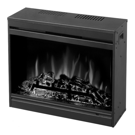
Muskoka MFB28-2 Use & Care Manual
Electric fireplace insert
Hide thumbs
Also See for MFB28-2:
- Use & care manual (14 pages) ,
- Instructions for use manual (9 pages)
Table of Contents
Advertisement
Available languages
Available languages
eleCtriC FirePlaCe insert
aPPareil de Foyer éleCtriqUe insérable
inserto Para el hoGar eléCtriCo
Use & Care GUide
GUide d'Utilisation et d'entretien
ManUal d Uso y CUidado
Please read this manual before installing and
using your firebox
If the InformatIon In thIs manual Is not
followed exactly, an electrIcal shock or
fIre may result causIng ProPerty damage,
Personal Injury or loss of lIfe
Model / Modèle / Modelo: MFb28-2
Veuillez lire ce manuel avant l'installation et
l'utilisation de votre foyer
sI les renseIgnements de ce manuel ne
sont Pas exactement suIVIs, un choc
électrIque ou un IncendIe Peut surVenIr,
et causer des dommages, des blessures
ou la Perte de VIe
Por favor lea las instrucciones de instalación y de
operación antes de usar este caja de fuego
sI no sIgue exactamente la InformacIón en
este manual, Podría resultar en choques
eléctrIcos o IncendIo que Pueden causar
daños a la ProPIedad, lesIones Personales
o la PérdIda de la VIda.
re
Advertisement
Table of Contents

Subscribe to Our Youtube Channel
Related Manuals for Muskoka MFB28-2


Summary of Contents for Muskoka MFB28-2
-
Page 1: Electric Fireplace Insert
FirePlaCe insert aPPareil de Foyer éleCtriqUe insérable inserto Para el hoGar eléCtriCo Model / Modèle / Modelo: MFb28-2 Use & Care GUide GUide d’Utilisation et d’entretien ManUal d Uso y CUidado Please read this manual before installing and Veuillez lire ce manuel avant l’installation et Por favor lea las instrucciones de instalación y de... -
Page 2: Important Instructions
Thank you for purchasing a Muskoka ® Electric Fireplace Insert. Important: Read all instructions and warnings carefully before starting installation. Failure to follow these instructions may result in a possible electric shock, fire hazard and will void the warranty. ImpoRtant InstRuctIons... -
Page 3: Grounding Instructions
All 3 trims attach to the firebox by inserting and tightening 3 screws. Both the left and right side trim attach to the mantel front by inserting and tightening 3 screws The top trim does not attach to the mantel, just the firebox. spEcIFIcatIons mFB28-2 Fireplace Insert 27.2” x 9.7” x 23.1” dimensions W x d x H 69.1 cm x 24.5 cm x 58.8 cm... -
Page 4: Electrical Connection
ELEctRIcaL connEctIon A 15 Amp, 120 Volt, 60 Hz circuit with a properly grounded outlet is required to operate this appliance. Preferably, the fireplace insert will be on a dedicated circuit as other appliances on the same circuit may cause the circuit breaker to trip or the fuse to blow when the heater is in operation. -
Page 5: Front Access Panel
opERatInG InstRuctIons The firebox master power “on/off” switch must be switched “on” before any of the control functions, (on the firebox and/ or remote control) will operate. NOTE: The master switch does not have to be turned off when the firebox is not being used for brief time periods. -
Page 6: Instructions Importantes
Merci d’avoir acheté un appareil de foyer fermé électrique Muskoka ® . Important : Lisez attentivement toutes les instructions et les avertissements avant de commencer l’installation. À défaut de suivre ces instructions, un choc électrique peut survenir de même qu’un risque d’incendie et l’annulation de la garantie. -
Page 7: Spécifications
à l’avant de mantel en insérant et en serrant 3 vis L’équilibre supérieur n’attache pas au mantel, juste le foyer. spécIFIcatIons mFB28-2 Foyer Insérable 27.2” x 9.7” x 23.1” dimensions W x d x H 69.1 cm x 24.5 cm x 58.8 cm... -
Page 8: Connection Électrique
connEctIon éLEctRIQuE Un circuit de 15 Amp, 120 Volts, 60 Hz avec prise de courant correctement mise à la terre est requis pour le fonctionnement de cet appareil. De préférence, le foyer insérable sera sur un circuit distinct car d’autres appareils sur le même circuit pourraient causer au disjoncteur de mal fonctionner ou le fusible de griller lorsque la chaufferette est en fonctionnement. -
Page 9: Instructions De Fonctionnement
6. Insérez les nouvelles ampoules. 7. Poussez le support coulissant et remettez les panneaux d'accès en place. 8. Insérez les vis et serrez-les dans chaque panneau retiré au cours de l'étape 4. 9. Placez le commutateur d'alimentation principal de la chambre de combustion en position ON (marche) - le pilote rouge s'allume. -
Page 10: Utilisation Des Commandes
utILIsatIon dEs commandEs manuELLEs sItuéEs dERRIÈRE LE pannEau d'accÈs InFéRIEuR aVant dE La cHamBRE dE comBustIon : 1. on/oFF (marche/arrêt) (le commutateur d'alimentation principal doit être en position de marche « ON ») Appuyez sur le bouton marche/arrêt (on/off) de la chambre de combustion pour utiliser la flamme uniquement. -
Page 11: Instrucciones Importantes
Gracias por adquirir un inserto para el hogar eléctrico Muskoka ® . Importante: Lea todas las instrucciones y advertencias con cuidado antes de comenzar la instalación. de no seguir estas instrucciones podría resultar en la posibilidad de choques eléctricos, peligro de incendio y anularían la garantía. -
Page 12: Instrucciones Del Usuario
3 tornillos. El soporte superior no se fija al mueble, solo a la caja de fuego eléctrica. EspEcIFIcacIonEs mFB28-2 Fogón Inserto 27.2” x 9.7” x 23.1”... -
Page 13: Conexión Eléctrica
conExIón ELéctRIca Para el funcionamiento correcto de este aparato se necesita un circuito de 15 amperios, 120 voltios, 60 Hz con un tomacorriente debidamente conectado a tierra. Preferentemente, el inserto para hogar deberá contar con un circuito exclusivo, ya que otros aparatos en el mismo circuito pueden disparar o quemar al fusible cuando está funcionando el calefactor. -
Page 14: Instrucciones De Operación
6. Instale las lámparas nuevas. 7. Empuje las correderas y vuelva a colocar en su lugar los paneles de acceso. 8. Inserte y ajuste los tornillos en cada panel del cual fueron retirados en el paso 4. 9. Gire el interruptor de potencia principal de “encendido/apagado” hacia la posición “on” (encendido) y se encenderá la luz piloto indicadora de color rojo. - Page 15 uso dE Los contRoLEs manuaLEs uBIcados En EL caLEntadoR dEtRás dEL panEL dE accEso dELantERo InFERIoR : 1. on/oFF (El interruptor de potencia principal debe estar en posición “on”). Presione el botón “on/off” del calentador, (sólo) el efecto llama se encenderá. Para apagar el calentador vuelva a presionar el botón “on/off”.
Need help?
Do you have a question about the MFB28-2 and is the answer not in the manual?
Questions and answers