
Related Manuals for Icop PMX-057T-5A


Summary of Contents for Icop PMX-057T-5A
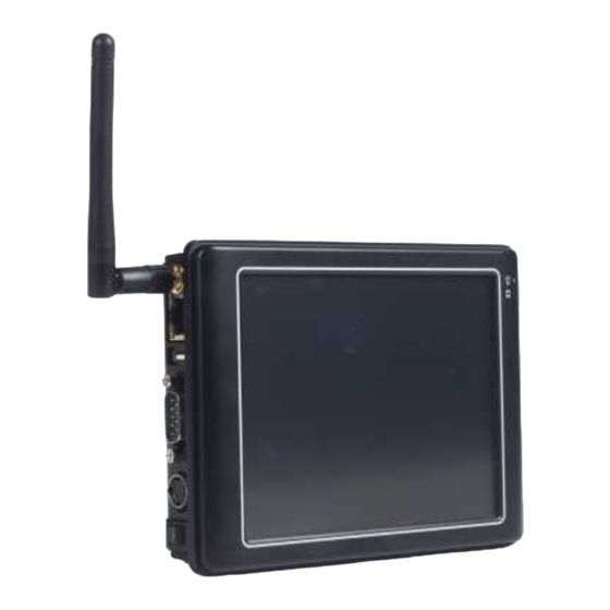
- Page 1 PMX-057T-5A / PMX-057T-8A PMX-057T-5A-512 / PMX-057T-8A-512 DM&P Vortex86MX Panel PC with 5.7” VGA TFT LCD User’s Manual (Revision 1.1A)
-
Page 2: Safety Information
No part of this manual may be reproduced, copied, translated or transmitted, in whole or in part, in any form or by any means without the prior written permission of the ICOP Technology Inc. Copyright 2011 ICOP Technology Inc. -
Page 3: Table Of Contents
T a b l e C o n t e n t s T a b l e o f C o n t e n t s ............. iii C h a p t e r 1 General Information..…………………………………1 Product Description .......... - Page 4 This page is blank...
-
Page 5: Chapter 1 General Information
C h a p t e r General Information Product Description PMX-057T is an ultra compact platform for the present demanding embedded and productive applications. It has new Vortex86MX SoC CPU which consumes only minimum power requirement when running at 1GHz, and DDR2 memory provides faster data transfer rate. By using 5.7”... -
Page 6: Product Specification
1.2 Product Specification CPU Board Specifications DM&P Vortex86MX 1GHz L1:16KB I-Cache, 16KB D-Cache Cache L2: 256KB Cache BIOS AMI BIOS Memory 512MB/1GB DDR2 onboard Watchdog Timer Software programmable from 30.5u to 512 seconds x 2 sets Integrated 10/100M Ethernet Audio HD Audio-Realtek ALC262 CODEC Compact Flash Type I/II slot Internal Drives... - Page 7 LCD Specifications Display Type 5.7” TFT LCD Backlight Unit Display Resolution 640(W) x 480(H) Brightness (cd/m 500 nits Contrast Ratio 300:1 Display Color 262,144 Dot Pitch (mm) 0.06 x 0.18 Vertical 100 Viewing Angle Horizontal 140 Backlight Lifetime 25,000 hrs Touchscreen Type Analog Resistive...
-
Page 8: Inspection Standard For Tft-Lcd Panel
Inspection standard for TFT-LCD Panel DEFECT TYPE LIMIT Note φ<0.15mm Ignore 0.15mm ≦ φ ≦ 0.5mm N ≦ 4 SPOT Note1 0.5mm<φ 0.03mm<W ≦ 0.1mm, L ≦ 5mm N ≦ 3 FIBER Note1 VISUAL INTERNAL 1.0mm<W, 1.5mm<L DEFECT φ<0.15mm Ignore POLARIZER BUBBLE 0.15mm ≦... - Page 9 [Note1] W : Width[mm], L : Length[mm], N : Number, φ: Average Diameter [Note2] Bright dot is defined through 6% transmission ND Filter as following. PMX-057T DM&P Vortex86MX Panel PC with 5.7” VGA TFT LCD...
- Page 10 [Note3] C Area: Center of display area C Area: Outer of display area [Note4] Judge defect dot and adjacent dot as following. Allow below (as A, B, C and D status) adjacent defect dots, including bright and dart adjacent dot. And they will be counted 2 defect dots in total quantity.
-
Page 11: Product Dimension
1.4 Product Dimension PMX-057T DM&P Vortex86MX Panel PC with 5.7” VGA TFT LCD... -
Page 12: Ordering Information
1.5 Ordering Information Part Number Description PMX-057T-5A 5.7” Panel PC w/1GB DDR2/2USB/Line-Out/LAN/COM/CF/MicroSD/Power Adapter PMX-057T-8A 5.7” Panel PC w/1GB DDR2/2USB/Line-Out/LAN/COM/CF/MicroSD/8-35 DC support 1.6 Packing List Part Number Package PMX-057T-5A PMX-057T-5A Power-20W-3PIN PMX-057T-8A PMX-057T-8A PMX-057T-5A-512 PMX-057T-5A-512 Power-20W-3PIN ... -
Page 13: Chapter 2 System Installation
C h a p t e r 2 System Installation 2.1 CPU Board Outline PMX-057T DM&P Vortex86MX Panel PC with 5.7” VGA TFT LCD... -
Page 14: Connector Summary
2.2 Connector Summary Summary Table Description Type of Connections Pin nbrs. CF Master/Slave Switch On/OFF Slide Switch 6-pin External USB Connector 6-pin External USB Connector USB (Touchscreen) 5-pin 2.0mm 5-pin wafer PS/2 Keyboard 5-pin 2.54mm 5-pin box header PS/2Keyboard/Mouse 6-pin External Mini DIN Socket COM2(RS232/422/485) 9-pin... -
Page 15: Connector Pin Assignments
2.3 Connector Pin Assignments J1: CF Master/Slave Switch Pin # Signal Name Master Slave J3: USB Pin # Signal Name Pin # Signal Name USBD2- USBD2+ J4: USB Pin # Signal Name Pin # Signal Name USBD3- USBD3+ J5: USB (Optional) Pin # Signal Name USBD1-... - Page 16 KBDATA MSDATA J10: COM1 RS232/422/485 (Change setting by BIOS) Pin # Signal Name Pin # Signal Name DCD1/ 422TX- / RS485- RXD1 / 422TX+ / RS485+ TXD1 / 422RX+ DTR1 / 422RX- DSR1 RTS1 CTS1 J14: VGA Signal Signal Pin # Pin # Name Name...
- Page 17 J24: MIC-IN Pin # Signal Name MICVREF MIC-IN J25: COM3 (TX, RX) Pin # Signal Name PMX-057T DM&P Vortex86MX Panel PC with 5.7” VGA TFT LCD...
- Page 18 TXD3 RXD3 J26: COM4 (TX, RX) Pin # Signal Name TXD4 RXD4 J31: 4-Wires Touch connector Pin # Signal Name J32: USB (WiFi Optional) Pin # Signal Name Pin # Signal Name USBD2- USBD2+ PWR: Power Connector (5A) Pin # Signal Name PWR: Power Connector (8A) Pin #...
-
Page 19: External I/O Overview
2.4 External I/O Overview PMX-057T-8A/ PMX-057T-8A-512 PMX-057T-5A/ PMX-057T-5A-512 (Note1: Wireless is optional) (Note2: COM1 RS232/422/485 is selected by BIOS setting) PMX-057T DM&P Vortex86MX Panel PC with 5.7” VGA TFT LCD... -
Page 20: Power Switch
2.5 External I/O Pin Assignment Power Switch Pin # Status Power Connector (5A) Signal Name Pin # Power Connector (8A) Signal Name Pin # +8 ~ 35V J10: COM1 RS232/422/485 (Change setting by BIOS) Pin # Signal Name Pin # Signal Name DCD1/422TX-/RS485- RXD1/422TX+/RS485+... - Page 21 Audio Line-Out Signal Pin # Name LOUTL Open Touch Open Touch VREFOUT Pin # Signal Name USB0- USB0+ GGND GGND RJ45 Pin # Signal Name Pin # Signal Name FTXD+ FTXD- FRXIN+ FRXIN- PS/2 Keyboard/Mouse Pin # Signal Name KBCLK PMCLK KBDAT PMDAT...
-
Page 22: System Mapping
2.6 System Mapping PMX-057T DM&P Vortex86MX Panel PC with 5.7” VGA TFT LCD... - Page 23 PMX-057T DM&P Vortex86MX Panel PC with 5.7” VGA TFT LCD...
- Page 24 PMX-057T DM&P Vortex86MX Panel PC with 5.7” VGA TFT LCD...
-
Page 25: Watchdog Timer
2.7 Watchdog Timer There are two watchdog timers in PMX-057T, we also provide DOS, Linux and WinCE example for your reference. For more technical support, please visit: http://tech.icop.com.tw or download the PDF file: http://www.dmp.com.tw/tech PMX-057T DM&P Vortex86MX Panel PC with 5.7” VGA TFT LCD... -
Page 26: Chapter 3 Driver Installation
Professional, and Windows Embedded standard (XPE). (Linux can use with Compact Flash card only.) Please get the drivers from ICOP official website: http://tech.icop.com.tw/ PMX-057T also supports most of the popular Linux distributions, for more detail information, please visit DMP official website: http://www.dmp.com.tw/tech/vortex86mx/. -
Page 27: Pmx-057T Development Note
1-Please visit technical website to get more information: http://tech.icop.com.tw/ <Enhance CF to run the UDMA2/4> 1-Please select ICOP “ICF Card” to supporting UDMA 2/4 Mode. <How to boot up from the Micro SD card> 1-Get into the BIOS setup Utility... -
Page 28: Bios Defaul Setting
3.2. BIOS Default setting If the system cannot be booted after BIOS changes are made, Please follow below procedures in order to restore the CMOS as default setting. Press “End” Key, when the power on Press <Del> to enter the AMI BIOS setup ... -
Page 29: Warranty
Warranty This product is warranted to be in good working order for a period of one year from the date of purchase. Should this product fail to be in good working order at any time during this period, we will, at our option, replace or repair it at no additional charge except as set forth in the following terms.
Need help?
Do you have a question about the PMX-057T-5A and is the answer not in the manual?
Questions and answers