Table of Contents
Advertisement
Quick Links
Advertisement
Table of Contents

Related Manuals for Icop PPC-104T-APL


Summary of Contents for Icop PPC-104T-APL
- Page 1 User’s Manual PPC-104T-APL Intel® Apollo Lake Processor Compact Panel PC with 10.4” Resistive Touch Screen PPC-104T-APL-N4-4G PPC-104T-APL-N4-8G PPC-104T-APL-N3-4G (Build to order) PPC-104T-APL-N3-8G (Build to order) (Revision 1.0A) PPC-104T-APL User’s Manual IUMPPC104TAPL-01 Ver.1.0A Jun, 2019...
- Page 2 REVISION DATE VERSION DESCRIPTION 2019/6/28 Version 1.0A New Release PPC-104T-APL User’s Manual IUMPPC104TAPL-01 Ver.1.0A Jun, 2019...
-
Page 3: Trademarks Acknowledgment
All names mentioned herewith are served for identification purpose only. For more detailed information or if you are interested in other ICOP products, please visit our official websites at: Global: www.icop.com.tw ... -
Page 4: Safety Information
Input voltage +12VDC Operating temperature between 0~+60°C (+32~+140°F). Keep PPC-104T-APL away from humidity. When a M.2 2242 or 2.5” Hard Disk/SSD storage is the main operating system storage, please turn off power before inserting or removing. Do not open the cabinet to avoid electrical shock. -
Page 5: Table Of Contents
4.4 BIOS COM2 Setting (Change Settings) ..............37 4.5 BIOS AT Mode Setting (Support Auto-Power On Function) ........39 4.6 BIOS Serial Port Console Redirection ..............41 4.7 BIOS Load Default Setting ..................43 Warranty ......................... 44 PPC-104T-APL User’s Manual IUMPPC104TAPL-01 Ver.1.0A Jun, 2019... -
Page 6: 1 General Information
General Information 1.1 Product Description 1.2 Product Specifications 1.3 Inspection standard for TFT-LCD Panel 1.4 Product Dimensions 1.5 Mounting Instruction 1.6 Ordering Information PPC-104T-APL User’s Manual IUMPPC104TAPL-01 Ver.1.0A Jun, 2019... -
Page 7: Product Description
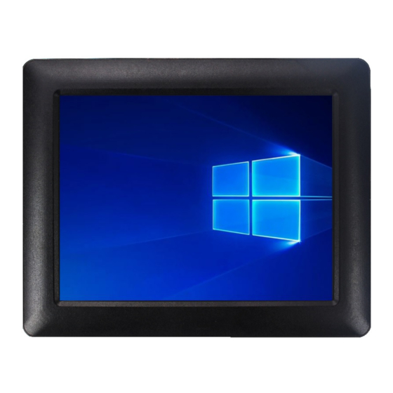
1.1 Product Description ICOP Technology Inc. is proudly going to release a brand new Panel PC, which offers fanless design, low power consumption, and IP65 front panel. The PPC-104T-APL is powered by Intel® Apollo Lake N4200/N3350 processor, and 4GB / 8GB SO-DIMM DDR3L module that handles processing more efficiently and provides faster performance. -
Page 8: Product Specifications
RJ45 x 1 Audio-Out Mic-In MECHANICAL & ENVIRONMENT Power Requirement +12 VDC Power Adapter +12VDC@ 3.33A (40W) Operating Temperature 0~+60°C (+32~+140°F) Storage Temperature -20~+70°C (-4~ +158°F) Operating Humidity 0% ~ 90% Relative Humidity, Non-Condensing PPC-104T-APL User’s Manual IUMPPC104TAPL-01 Ver.1.0A Jun, 2019... -
Page 9: Lcd Specifications
0.264 (H) x 0.264 (V) Viewing Angle Vertical 110 , Horizontal 140 Backlight Lifetime 50,000 hrs TOUCHSCREEN Type Analog Resistive Resolution Continuous Transmittance Controller USB interface Software Driver Linux, Win10, Win10 IoT Durability 1 million PPC-104T-APL User’s Manual IUMPPC104TAPL-01 Ver.1.0A Jun, 2019... -
Page 10: Inspection Standard For Tft-Lcd Panel
(1) One pixel consists of 3 sub-pixels, including R, G, and B dot. (Sub-pixel = Dot) (2) Little bright Dot acceptitable under 6% ND-Filter. (3) If require G0 grand (Total dot N≦0), please contact region sales. PPC-104T-APL User’s Manual IUMPPC104TAPL-01 Ver.1.0A Jun, 2019... - Page 11 [ Note 2 ] Bright dot is defined through 6% transmission ND Filter as following. [ Note 3 ] Display area C Area: Center of display area O Area: Outer of display area PPC-104T-APL User’s Manual IUMPPC104TAPL-01 Ver.1.0A Jun, 2019...
- Page 12 The defects that are not defined above and considered to be problem shall be reviewed and discussed by both parties. Defects on the Black Matrix, out of Display area, are not considered as a defect or counted. PPC-104T-APL User’s Manual IUMPPC104TAPL-01 Ver.1.0A Jun, 2019...
-
Page 13: Product Dimensions
1.4 Product Dimensions PPC-104T-APL User’s Manual IUMPPC104TAPL-01 Ver.1.0A Jun, 2019... -
Page 14: Mounting Instruction
1.5 Mounting Instruction 1.5.1 VESA Mounting PPC-104T-APL series support VESA Mount that is an optional for ordering. Please contact your region sales for ordering. Ordering part number: VESA-MT-PPC-APL-SET 1. Place VESA bracket and VESA-MT-PPC-APL-SET together. 2. Lock 4 screws and nuts on both of VESA bracket and VESA-MT-PPC-APL-SET. -
Page 15: Panel Mounting
1.5.2 Panel Mounting PPC-104T-APL series support clamp mount that is an optional for ordering. Please contact your region sales for ordering. Ordering part number: PANEL-MT-PPC-APL-SET Please refer the Section 1.4 to make a cutout hole on your mechanical or frame. -
Page 16: Ordering Information
4. RAM:Code 10~11。 4G:4GB. 8:8GB. PS: Power adapter and cord must be showed separate because different county has different power cord. The unit price includes power adapter and cord as below. POWER-12V3.33A-FSP POWERCABLE-FSP-US / POWERCABLE-FSP-EU PPC-104T-APL User’s Manual IUMPPC104TAPL-01 Ver.1.0A Jun, 2019... - Page 17 AC – DC power adapter / DC12V @ 3.33A (AC 90 ~ 240V Input) POWERCABLE-FSP-US US/Euro power cord for POWER-12V3.33A-FSP / POWERCABLE-FSP-EU VESA-MT-PPC-APL-SET VESA mount bracket set PANEL-MT-PPC-APL-SET Panel mount set with clamps and screws PPC-104T-APL User’s Manual IUMPPC104TAPL-01 Ver.1.0A Jun, 2019...
-
Page 18: 2 System Installation
System Installation 2.1 CPU Board Outline 2.2 Connector Summary 2.3 Connector Pin Assignments 2.4 External I/O Overview 2.5 External I/O Pin Assignment PPC-104T-APL User’s Manual IUMPPC104TAPL-01 Ver.1.0A Jun, 2019... -
Page 19: Cpu Board Outline
2.1 CPU Board Outline PPC APL CPU Board PPC-104T-APL User’s Manual IUMPPC104TAPL-01 Ver.1.0A Jun, 2019... -
Page 20: Connector Summary
2.54mm 4-pin pin header 4-pin Audio Header 2.0mm 9-pin pin header 9-pin GPIO Header (Reserved) 2.0mm 10-pin pin header 10-pin Inverter 2.0mm 8-pin box header 8-pin RTC Battery Header 1.25mm 2-pin box header 2-pin PPC-104T-APL User’s Manual IUMPPC104TAPL-01 Ver.1.0A Jun, 2019... -
Page 21: Connector Pin Assignments
LVDSB_D0- LVDSB_D0+ Pin # Signal Name Pin # Signal Name NC/DDC_DAT NC/DDC_CLK DCD2 DSR2 RXD2 RTS2 TXD2 CTS2 LVDSA_D3+ LVDSA_D3- DTR2 LVDSA_CLK+ LVDSA_CLK- LVDSA_D2+ LVDSA_D2- LVDSA_D1+ LVDSA_D1- LVDSA_D0+ LVDSA_D0- LCD_VDD LCD_VDD LCD_VDD LCD_VDD PPC-104T-APL User’s Manual IUMPPC104TAPL-01 Ver.1.0A Jun, 2019... - Page 22 Signal Name Pin # Signal Name GPIO80 GPIO81 GPIO82 GPIO83 GPIO84 GPIO85 GPIO86 GPIO87 J17: Inverter Pin # Signal Name Backlight_Enable Backlight_PWM Backlight LED VCC Backlight LED VCC Backlight UP SW Backlight DN SW PPC-104T-APL User’s Manual IUMPPC104TAPL-01 Ver.1.0A Jun, 2019...
-
Page 23: External I/O Overview
2.4 External I/O Overview NOTE: COM1 RS232/422/485 is selected by BIOS setting. Please refer the section, 4.6 to set the function in the BIOS setup. PPC-104T-APL User’s Manual IUMPPC104TAPL-01 Ver.1.0A Jun, 2019... - Page 24 PPC-104T-APL User’s Manual IUMPPC104TAPL-01 Ver.1.0A Jun, 2019...
-
Page 25: External I/O Pin Assignment
Name DSR2 SIM-VCC SIM-RST RTS2 CTS2 SIM-CLK SIM-VPP SIM-IO GigaLAN USB2.0 Signal Signal Pin # Signal Name Pin # Pin # Name Name TP0+ TP0- USB0- TP1+ TP2+ USB0+ TP2- TP1- TP3+ TP3- PPC-104T-APL User’s Manual IUMPPC104TAPL-01 Ver.1.0A Jun, 2019... - Page 26 Line-Out Signal Name LINEOUT2-L LINEOUT2-R AUDIO_GND Mic-in Signal Pin # Name MIC-L MIC-R AUDIO_GND PPC-104T-APL User’s Manual IUMPPC104TAPL-01 Ver.1.0A Jun, 2019...
-
Page 27: 3 Hardware Installation
Hardware Installation PPC-104T-APL supports various kinds of storages for industrial application, divided into M.2 2242 SATA (M-Key) and 2.5” SATAIII HDD/SSD. 3.1 Installing the M.2 2242 SATA 3.2 Installing the 2.5” SATA HDD/SSD 3.3 Installing the Mini-PCIe Module 3.4 Installing the Micro SIM Card (Must include 3G/4G Mini-PCIe Module in advance) PPC-104T-APL User’s Manual... -
Page 28: Installing The M.2 2242 Sata
0℃ ~ +70℃ IM242S-16G-M IM242S-32G-M 0℃ ~ +70℃ 0℃ ~ +70℃ IM242S-64G-M 0℃ ~ +70℃ IM242S-128G-M 0℃ ~ +70℃ IM242S-256G-M [STEP] Remove the 16 screws in a diagonal pattern as the image below. PPC-104T-APL User’s Manual IUMPPC104TAPL-01 Ver.1.0A Jun, 2019... - Page 29 Pull up rear cover carefully, which LCD, Backlight and Touch cables inside the rear cover and please be careful to open it. Remove the screw of M.2 Slot. PPC-104T-APL User’s Manual IUMPPC104TAPL-01 Ver.1.0A Jun, 2019...
- Page 30 Plug M.2 2242 Storage on M.2 Slot and lock the screw. Take the rear cover back and lock 16 screws. PPC-104T-APL User’s Manual IUMPPC104TAPL-01 Ver.1.0A Jun, 2019...
-
Page 31: Installing The 2.5" Sata Hdd/Sdd
3.2 Installing the 2.5” SATA HDD/SDD [STEP] Find the bag of screws from inside of the package box, and prepare those 4 screws in advance. Remove the 16 screws in a diagonal pattern as the image below. PPC-104T-APL User’s Manual IUMPPC104TAPL-01 Ver.1.0A Jun, 2019... - Page 32 Pull up rear cover carefully, which LCD, Backlight and Touch cables inside the rear cover and please be careful to open it. Plug SATA cable upon 2.5” SATA HDD/SSD and take it in the box. PPC-104T-APL User’s Manual IUMPPC104TAPL-01 Ver.1.0A Jun, 2019...
- Page 33 Lock the screws on the both of rear cover and 2.5” HDD/SSD. Take the rear cover back and lock 16 screws. PPC-104T-APL User’s Manual IUMPPC104TAPL-01 Ver.1.0A Jun, 2019...
-
Page 34: Installing The Mini-Pcie Module
Remove the 16 screws in a diagonal pattern as the image below. Pull up rear cover carefully, which LCD, Backlight and Touch cables inside the rear cover and please be careful to open it. PPC-104T-APL User’s Manual IUMPPC104TAPL-01 Ver.1.0A Jun, 2019... - Page 35 Remove the screw of Mini-PCIe Slot. Plug Mini-PCIe Module upon the slot and lock the screws. Take the rear cover back and lock 16 screws. PPC-104T-APL User’s Manual IUMPPC104TAPL-01 Ver.1.0A Jun, 2019...
-
Page 36: Installing The Micro Sim Card (Must Include 3G/4G Mini-Pcie Module In Advance)
3.4 Installing the Micro SIM Card (Must include 3G/4G Mini-PCIe Module in advance) [STEP] Please refer the section, 3.3 to install 3G/4G Mini-PCIe Module in advance. Plug Micro SIM Card on the slot. PPC-104T-APL User’s Manual IUMPPC104TAPL-01 Ver.1.0A Jun, 2019... -
Page 37: 4 Drivers And Bios Instruction
4.2 BIOS Hot Key 4.3 BIOS COM1 Setting (RS232/RS422/RS485) 4.4 BIOS COM2 Setting (Change Settings) 4.5 BIOS AT Mode Setting (Support Auto-Power On Function) 4.6 BIOS Serial Port Console Redirection 4.7 BIOS Load Default Setting PPC-104T-APL User’s Manual IUMPPC104TAPL-01 Ver.1.0A Jun, 2019... -
Page 38: Operating System Support And Drivers
4.1 Operating System Support and Drivers The PPC-104T-APL provides the Win10 drivers for Normal Win10 and Win10 IoT Enterprise. Please get the drivers from ICOP technical support URL: https://www.icop.com.tw/download_resource/PPC-104T-N4200?tags=18,81,34,35,38, 39,64,65&selected=35 For Linux, most Linux distributions support Intel® Apollo Lake Processor and user can install Linux upon PPC-104T-APL directly. -
Page 39: Bios Hot Key
4.2 BIOS Hot Key After power on, it supports BIOS hot key as below. Press < Del > to enter the AMI BIOS setup Press < F7 > to enter Popup Menu PPC-104T-APL User’s Manual IUMPPC104TAPL-01 Ver.1.0A Jun, 2019... -
Page 40: Bios Com1 Setting (Rs232/422/485)
COM1 can be set to be RS232/422/485 function. Please refer the instruction as below. (1) In the BIOS Setup, please go to “Advanced” and “Super IO Configuration”. (2) Go to “Serial Port 1 Configuration”. PPC-104T-APL User’s Manual IUMPPC104TAPL-01 Ver.1.0A Jun, 2019... - Page 41 (3) Go to Transmission Mode and set RS232/422/485 function. (4) After setting, please press “F4” key to save & exit. PPC-104T-APL User’s Manual IUMPPC104TAPL-01 Ver.1.0A Jun, 2019...
-
Page 42: Bios Com2 Setting (Change Settings)
4.4 BIOS COM2 Setting (Change Settings) COM2 can be changed settings as below. (1) In the BIOS Setup, please go to “Advanced” and “Super IO Configuration”. (2) Go to “Serial Port 2 Configuration”. PPC-104T-APL User’s Manual IUMPPC104TAPL-01 Ver.1.0A Jun, 2019... - Page 43 (3) Go to “Change Settings” and set IO address and IRQ if you want to have the default, IO=2F8h and IRQ=3. (4) After setting, please press “F4” key to save & exit. PPC-104T-APL User’s Manual IUMPPC104TAPL-01 Ver.1.0A Jun, 2019...
-
Page 44: Bios At Mode Setting (Support Auto-Power On Function)
4.5 BIOS AT Mode Setting (Support Auto-Power On Function) PPC-104T-APL supports “Auto-Power On function”, user doesn’t need to press “power button” for system power on and just needs to plug power source input and system will be power on automatically. - Page 45 (3) After setting, please press “F4” key to save & exit. Note: After system shut down by operating system, PPC-104T-APL will be power-off. For next booting up, user just needs to re-plug power adapter or power reset again, while system will be boot-up automatically.
-
Page 46: Bios Serial Port Console Redirection
4.6 BIOS Serial Port Console Redirection PPC-104T-APL supports Serial Port Console Redirection as below. (1) Go to “Advanced” and “Serial Port Console Redirection”. (2) Set “Console Redirection” to be “Enabled”. PPC-104T-APL User’s Manual IUMPPC104TAPL-01 Ver.1.0A Jun, 2019... - Page 47 [VT100+]: Extended VT100 to support color, function keys, etc.; [VT-UTF8]: Uses UTF8 encoding to map Unicode chars onto 1 or more Bytes. (4) After setting, please press “F4” key to save & exit. PPC-104T-APL User’s Manual IUMPPC104TAPL-01 Ver.1.0A Jun, 2019...
-
Page 48: Bios Load Default Setting
4.7 BIOS Load Default Setting (1) Press “F3” key to load optimized defaults. (2) After setting, please press “F4” key to save & exit. PPC-104T-APL User’s Manual IUMPPC104TAPL-01 Ver.1.0A Jun, 2019... -
Page 49: Warranty
Merchandise Authorization (RMA) number. Returned goods should always be accompanied by a clear problem description. All Trademarks appearing in this manuscript are registered trademark of their respective owners. All Specifications are subject to change without notice. ©ICOP Technology Inc. 2019 PPC-104T-APL User’s Manual IUMPPC104TAPL-01 Ver.1.0A Jun, 2019...
Need help?
Do you have a question about the PPC-104T-APL and is the answer not in the manual?
Questions and answers