Table of Contents
Advertisement
Quick Links
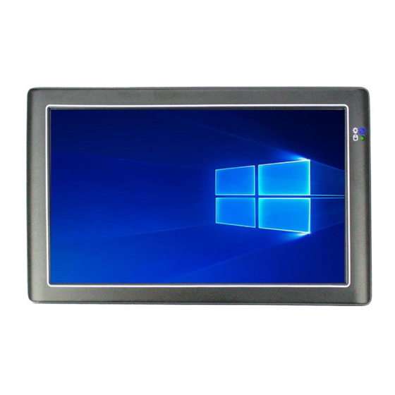
PN8M
Panel PC Series with 9" TFT LCD
Model:
PN8M-090T-5A-N4FM / PN8M-090T-8A-N4FM
PN8M-090T-5A-B4FM / PN8M-090T-8A-B4FM
PN8M-090T-5A-N4FS / PN8M-090T-8A-N4FS
PN8M-090T-5A-B4FS / PN8M-090T-8A-B4FS
PN8M-090T-5A-N5GM / PN8M-090T-8A-N5GM
PN8M-090T-5A-B5GM / PN8M-090T-8A-B5GM
PN8M-090T-5A-N5GS / PN8M-090T-8A-N5GS
PN8M-090T-5A-B5GS / PN8M-090T-8A-B5GS
User's Manual
(Revision 1.1A)
i
Advertisement
Table of Contents

Related Manuals for Icop PN8M Series


Summary of Contents for Icop PN8M Series
- Page 1 PN8M Panel PC Series with 9” TFT LCD Model: PN8M-090T-5A-N4FM / PN8M-090T-8A-N4FM PN8M-090T-5A-B4FM / PN8M-090T-8A-B4FM PN8M-090T-5A-N4FS / PN8M-090T-8A-N4FS PN8M-090T-5A-B4FS / PN8M-090T-8A-B4FS PN8M-090T-5A-N5GM / PN8M-090T-8A-N5GM PN8M-090T-5A-B5GM / PN8M-090T-8A-B5GM PN8M-090T-5A-N5GS / PN8M-090T-8A-N5GS PN8M-090T-5A-B5GS / PN8M-090T-8A-B5GS User’s Manual (Revision 1.1A)
- Page 2 Revision Date Version Description 2020/07/24 Version 1.0A Initial Release 2020/08/04 Version 1.1A Correct section 2.5, System Status LED...
- Page 3 Manual No. IUMPN8M090-01 Ver.1.1A Aug, 2020 Trademarks Acknowledgment PN8M is the registered trademark of ICOP Technology Inc. Other brand names or product names appearing in this document are the properties and registered trademarks of their respective owners. All names mentioned herewith are served for identification purpose only.
-
Page 4: Table Of Contents
Table of Contents Table of Contents ......................iii .General Information ..................1 Product Description ............... 1 Product Specification ..............2 Inspection standard for TFT-LCD Panel .......... 4 Product Dimension ................ 9 Panel Mounting Instruction ............11 Ordering Information ..............13 Packing List ................... -
Page 5: General Information
1 .General Information 1.1 Product Description PN8M-090T is an ultra-compact platform for the present demanding embedded and productive applications. It has NXP i.MX8M Mini Cortex-A53 ARM Quad Core which consumes only minimum power requirement when running at 1.6GHz, and up 4GB LPDDR4 memory provides faster data transfer rate. By using 9” TFT LCD, PN8M-090T becomes the perfect choice for a limited budget. -
Page 6: Product Specification
1.2 Product Specification Table 1-1 Product Specification CPU Board Specifications i.MX8M Mini-1.6GHz Cortex-A53 ARM Quad-Core Cache L2: 512KB Cache Memory 1GB/2GB/4GB LPDDR4 onboard Watchdog Timer Support 3 Watchdog Timer Integrated Gigabit Ethernet Audio High Definition Audio 8GB / 16GB / 32GB / 64GB of eMMC onboard Internal Drives Micro SD slot (Like a card reader only) RS-232 x 1... - Page 7 Front Panel IP 65 Protection Certification CE / FCC / VCCI / Vibration / Shock (Coming soon) LCD Specifications Display Type 9” TFT LCD Backlight Unit Display Resolution 1024(W) x 600(H) Brightness (cd/m 300 nits Contrast Ratio 500 : 1 Display Color 262, 144 Active Area (mm)
-
Page 8: Inspection Standard For Tft-Lcd Panel
1.3 Inspection standard for TFT-LCD Panel Table 1-2 Inspection Standard DEFECT TYPE LIMIT Note φ<0.15mm Ignore 0.15mm≦φ≦0.5mm N≦4 SPOT Note1 0.5mm<φ 0.03mm<W≦0.1mm, L≦ N≦3 FIBER Note1 VISUAL INTER 1.0mm<W, 1.5mm<L DEFECT φ<0.15mm Ignore POLARIZER 0.15mm≦φ≦0.5mm N≦2 Note1 BUBBLE 0.5mm<φ Mura It’... - Page 9 [Note 1] W : Width[mm], L : Length[mm], N : Number, φ: Average Diameter. White / Black Spot Polarizer Bubble Fig 1-1 Fig 1-2 [Note 2] Bright dot is defined through 6% transmission ND Filter as following. Fig 1-3 PN8M-090T PN8M Panel PC Series with 9”...
- Page 10 [Note 3] C Area: Center of display area O Area: Outer of display area [Note 4] Judge defect dot and adjacent dot as following. Allow below (as A, B, C and D status) adjacent defect dots, including bright and dart adjacent dot. And they will be counted 2 defect dots in total quantity.
- Page 11 LCD display if the static image is kept for a period of time without any change. ICOP will suggest customers not to have static image on LCD for over 4 hours without any image movement and also enable screensaver to avoid image sticking issue if LCD displays need to be kept on for a long time.
- Page 12 3. After 5 mins, the mura must be disappeared completely. PN8M-090T PN8M Panel PC Series with 9” WSVGA TFT LCD...
-
Page 13: Product Dimension
1.4 Product Dimension PN8M-090T PN8M Panel PC Series with 9” WSVGA TFT LCD... - Page 14 Fig 1-4 Product Dimension PN8M-090T PN8M Panel PC Series with 9” WSVGA TFT LCD...
-
Page 15: Panel Mounting Instruction
1.5 Panel Mounting Instruction Cut a mounting hole in the panel. (Refer to PN8M‐090T Dimensions on page 7) (Note 1) Check and remove the twelve M3 screws in a diagonal pattern as image below if necessary. Place PN8M‐090T face‐down on a clean, flat surface. Slide the panel cutout around the back of PN8M‐090T, until the panel rests directly on the gasket. - Page 16 Note 1: It is strongly recommended that a professional machine shop cut the mounting hole in the panel. Note 2: The length for all twelve M3 screws will be according to the thickness of mounting panel. For example: The length of standard M3 screws for PN8M‐090T is 6mm.
-
Page 17: Ordering Information
G (16GB) S (SLC) 6 (3BG) H (32GB) 1. Product Code:Code 1~3。 PN8M:PN8M Series。 2. LCD Size:Code 4~7。 090T:9” LCD with touchscreen。 3. DC-Input Type:Code 8~9。 5A:Audio Line-out and Single DC5V Power Input。 8A:Audio Line-out and Support DC8~35V Power Input。... - Page 18 Table 1-3 Ordering Information PART NUMBER DESCRIPTION PN8M-090T-8A-B5GM PN8M-090T with i.MX8M Mini (Quad Core 1.6GHz), 2GB of LPDDR4, 16GB eMMC MLC, Wifi&BT and DC+8~35V PN8M-090T-8A-N5GM PN8M-090T with i.MX8M Mini (Quad Core 1.6GHz), 2GB of LPDDR4, 16GB eMMC MLC and DC+8~35V PN8M-090T-8A-B5GS PN8M-090T with i.MX8M Mini (Quad Core 1.6GHz), 2GB of LPDDR4, 16GB eMMC SLC, Wifi&BT and DC+8~35V...
-
Page 19: Packing List
1.7 Packing List Table 1-4 Packing List PART NUMBER PACKAGE PN8M-090T-8A-B5GM PN8M-090T-8A-B5GM WIRELESS-ANTENNA-157 PN8M-090T-8A-N5GM PN8M-090T-8A-N5GM PN8M-090T-8A-B5GS PN8M-090T-8A-B5GS WIRELESS-ANTENNA-157 PN8M-090T-8A-N5GS PN8M-090T-8A-N5GS PN8M-090T-8A-B4FM PN8M-090T-8A-B4FM WIRELESS-ANTENNA-157 PN8M-090T-8A-N4FM PN8M-090T-8A-N4FM Power-20W-3PIN-X & PowerHead-US/EU PN8M-090T-5A-B5GM PN8M-090T-5A-B5GM WIRELESS-ANTENNA-157 PN8M-090T-5A-N5GM PN8M-090T-5A-N5GM Power-20W-3PIN-X & PowerHead-US/EU Power-20W-3PIN-X & PowerHead-US/EU PN8M-090T-5A-B5GS PN8M-090T-5A-B5GS WIRELESS-ANTENNA-157 PN8M-090T-5A-N5GS... -
Page 20: System Installation
2 .System Installation 2.1 CPU Board Outline Fig 2-1 PN8M CPU Board PN8M-090T PN8M Panel PC Series with 9” WSVGA TFT LCD... -
Page 21: Connector Summary
2.2 Connector Summary Table 2-1 Summary Table Description Type of Connections Pin nbrs. Ethernet External RJ45 Connector 8-pin Micro SD Card Socket Micro SD Socket 9-pin Enable RS232/RS485 2.54mm 2-pin Header 2-pin Audio Line-Out 1.25mm Phone Jack 5-pin Audio Mic-in (Reserved) 1.25mm 4-pin Wafer 4-pin... -
Page 22: Connector Pin Assignments
2.3 Connector Pin Assignments J2: RJ45 J9: Audio Mic-in (Reserved) Pin # Signal Name Pin # Signal Name Pin # Signal Name Pin # Signal Name BI_DA+ BI_DA- MIC_IN GND_AUD BI_DB+ BI_DC+ GND_AUD MIC_IN BI_DC- BI_DB- BI_DD+ BI_DD- J10: USB 2.0 Pin # Signal Name Pin # Signal Name J4: Micro SD Card Socket USBD3-... - Page 23 J14: I2C (For External Gamma J22: Software Programming Firmware Programming) Port (Reserved) Pin # Signal Name Pin # Signal Name Pin # Signal Name Pin # Signal Name USBD1- I2C_SCL USBD1+ USBD1_ID I2C_SDA J16: USB 2.0 (For Touch Controller) TXD2 RXD2 Pin # Signal Name Pin # Signal Name PWR: Power Connector (5A)
-
Page 24: External I/O Overview
2.4 External I/O Overview { PN8M-090T-8A } Fig 2-2 PN8M-090T-8A I/O overview { PN8M-090T-5A } Fig 2-3 PN8M-090T-5A I/O overview {Note} 1. WLAN is optional 2. COM1 can be RS232/RS485 signals by jumper, J6 3. MicroSD Socket likes a reader for data wrting/reading only PN8M-090T PN8M Panel PC Series with 9”... -
Page 25: External I/O Pin Assignment
2.5 External I/O Pin Assignment Power Switch USB 2.0 Port Pin # Status Pin # Signal Name USB0- USB0+ Power Connector (5A) Pin # Signal Name GGND GGND Micro SD Card Socket (Like Card Reader Only) Power Connector (8A) Pin # Signal Name Pin # Signal Name DAT2... - Page 26 COM1 RS232 Pin # Signal Name Pin # Signal Name RXD1 TXD1 N/C or RS485+ N/C or RS485- RTS1 CTS1 RJ45 Pin # Signal Name Pin # Signal Name BI_DA+ BI_DA- BI_DB+ BI_DC+ BI_DC- BI_DB- BI_DD+ BI_DD- Software Programming Port (Reserved) Pin # Signal Name...
- Page 27 Power LED LED Color State Blue Power On System Status LED LED Color State System Status LED when system is active Green (LED on => System running) (LED off => System execute “poweroff”) PN8M-090T PN8M Panel PC Series with 9” WSVGA TFT LCD...
-
Page 28: The Settings For Normal And Developer Modes
3 .The Settings for Normal and Developer Modes 1. Remove the plastic cover. PN8M-090T PN8M Panel PC Series with 9” WSVGA TFT LCD... - Page 29 2. There are two modes, Normal and Develop Modes as below. Two switches setting for Normal mode, internal flash booting. Two switches setting for Developer mode, which allow user to write the image in the eMMC. PN8M-090T PN8M Panel PC Series with 9” WSVGA TFT LCD...
- Page 30 3. The Software Programming Cable for Developer Mode Ordering Part Number: CABLE-MINIDIN8P-30 (1) Please order this cable from ICOP. (2) Refer section 3.2 to set two switches to be developer mode. (3) Plug 8-pin male terminal. (4) Connect USB and serial console cables to your developer PC, and power on the system for system restore.
-
Page 31: Warranty
Returned goods should always be accompanied by a clear problem description. All Trademarks appearing in this manuscript are registered trademark of their respective owners. All Specifications are subject to change without notice. © ICOP Technology Inc. 2020 PN8M-090T PN8M Panel PC Series with 9” WSVGA TFT LCD...
Need help?
Do you have a question about the PN8M Series and is the answer not in the manual?
Questions and answers