Table of Contents
Advertisement
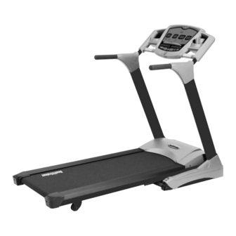
Owner's Manual
Health Trainer 65T Treadmill
Customer Service
(888) 340-0482
Keys Fitness Products
4009 Distribution Drive
Suite 250
Garland, TX 75041
www.keysfitness.com
CAUTION! Read all precautions and
instructions in this manual before
using this equipment.
415-00019
02/06 Rev B
Model Name : HT65T.1/HT65T.1-CE
Serial Number :
Write down for future reference
Serial Number Decal Location
Advertisement
Table of Contents

Related Manuals for Keys Fitness HealthTrainer HT65T.1


Summary of Contents for Keys Fitness HealthTrainer HT65T.1
- Page 1 4009 Distribution Drive Suite 250 Garland, TX 75041 www.keysfitness.com CAUTION! Read all precautions and instructions in this manual before using this equipment. Model Name : HT65T.1/HT65T.1-CE Serial Number : Write down for future reference 415-00019 02/06 Rev B Serial Number Decal Location...
-
Page 2: Table Of Contents
Table of Contents Important Safety Information Before You Start Assembly Moving Instructions Power Requirements Console Panel Functions Program Operation Program Profiles Monitoring Your Heart Rate Warm Up Exercises Changing to MPH or KM Calibration Sequence Belt Adjustment Maintenance Instructions Error Messages Troubleshooting Parts List Exploded View... -
Page 3: Important Safety Information
12. Never operate the treadmill where oxygen is being administered, or where aerosol products are being used. 13. Never insert any object or body parts into any opening. 14. For safety and to prevent damage to your treadmill, no more than one person should use the treadmill at a time. -
Page 4: Before You Start
Do not stand on the walking belt while pressing the Power button or Start/Stop button. Always adjust the speed of the treadmill in small increments as this treadmill is capable of high speeds. If you are taking medication, consult your physician to see if the medication will affect your exercise heart rate. -
Page 5: Assembly
Assembly The Health Trainer 65T Treadmill will require assembly before operating. After opening the box, remove any packing material from the treadmill. Do not throw away any packing materials until the unit is working properly. Place the base on a clean, level surface. Make sure the electrical cord will easily reach an electrical outlet. - Page 6 Assembly Assembly requires the included allen wrench. Do not plug in the power cord until all assembly steps are completed. Step 1: Place the left and right fenders through the tube of the left and right uprights as shown in Figure 1. Step 2: Slide the fenders up the upright assembly and pull the console harness through the hole in bottom of...
- Page 7 Assembly Step 3: Connect the console harness from inside the left upright to the console harness from the base assembly as shown in Figure 3. Next, attach left upright and right upright to base using allen bolts M8x15 (Qty. 8) and washer 9x22x2 mm (Qty.
- Page 8 Next, attach both left and right fenders to base using philip screw ST4.2x13 (Qty. 2) and philip screw M6x12 (Qty. 2). Move the treadmill to its final location (see sec- tion titled “Moving Instructions”). Adjust the leveler feet so that treadmill does not wobble while in use.
- Page 9 Assembly Congratulations!! You have completed the assembly of your new Health Trainer 65T Treadmill.
-
Page 10: Moving Instructions
Next, with a firm grasp on the handrail, care- fully tilt the treadmill back until it rolls freely on the wheels. Using extreme caution, move the treadmill to the desired location. -
Page 11: Power Requirements
This treadmill can be seriously damaged by sudden voltage changes in your home’s electrical power. Voltage spikes, surges, and noise interference can result from weather conditions or from other appliances being turned on or off. To reduce the possibility of treadmill damage, always use a dedicated surge protector (not includ- ed) with your treadmill. -
Page 12: Console Panel Functions
Console Panel Functions There are four display windows on the control panel to provide feedback information. INCLINE / PULSE WINDOW: INCLINE: Indicates incline in percent of grade 0-10% in 0.5 increments. CALORIES / DISTANCE WINDOW: CALORIES: Indicates estimated calories used based on 150 lb. person at the indicated speed, incline, and time. -
Page 13: Program Operation
Program Operation QUICK START / MANUAL MODE 1. Plug into a surge protector outlet. Attach the Safety Key on to the treadmill console. 2. Stand on the treadmill and straddle belt. Attach safety key clip to your clothes. 3. Press POWER button. There will be an eight (8) second delay after pressing the POWER button before data can be entered. -
Page 14: Program Operation
2. Press POWER button. There will be an eight (8) second delay before data can be entered. 3. There are three (3) pre-set and six (6) semi-custom pre-set programs on this unit. The treadmill includes FAT BURN, CARDIO, and WARM-UP programs. Press the PROGRAM UP or DOWN button to select which program you wish to use. -
Page 15: Program Profiles
1 2 3 4 5 6 7 8 9 1 0 The Warm Up Program is designed to gradually increase the treadmill Speed and Elevation in the first segment (warm up) and gradually decrease the treadmill Speed and Elevation in the last segment (cool down). -
Page 16: Monitoring Your Heart Rate
Monitoring Your Heart Rate Monitoring Your Heart Rate To obtain the greatest cardiovascular benefits from your exercise workout, it is important to work within your target heart rate zone. The American Heart Association (AHA) defines this target as 60%-75% percent of your maximum heart rate. -
Page 17: Monitoring Your Heart Rate
Monitoring Your Heart Rate TARGET HEART RATE ZONE 100% Serious athletic training range Cardiovascular conditioning range Fat burning range... -
Page 18: Warm Up Exercises
Warm Up Exercises EXERCISE GUIDELINES WARNING! Before beginning this or any exercise program, you should consult your physician. This is espe- cially important for individuals over the age of 35 or individuals with pre-existing health problems. Warming up prepares the body for the exercise by increasing circulation, supplying more oxygen to the mus- cles and raising body temperature. -
Page 19: Change To Mph Or Kph
1) Turn power OFF on the console. (Do not unplug treadmill.) Attach the magnet safety key to the console. 2) Activate the calibration mode switch by inserting the eraser end of a pencil into the opening in the backside of the console (see diagram below). -
Page 20: Calibration Sequence
16. When Speed and Incline calibration has finished, press Power button twice, display should be blank, and treadmill should be ready for use. To avoid possible damage to the treadmill and the possibility of injury, do not operate the treadmill until the problem is corrected. Call Keys Fitness Customer Service at (888)-340-0482 if problem per- sists. -
Page 21: Belt Adjustment
“Walking Belt Slipping” instructions. WALKING BELT IS SHIFTING TO THE RIGHT (Diagram 2) First, turn the treadmill on to run at 1 mph. Using the hex key pro- vided, turn the right rear roller adjustment bolt ¼ turn in the clock- wise direction. -
Page 22: Maintenance Instructions
Keys Fitness recommends “Lube N Walk” for cleaning and lubri- cating the treadmill belt and deck. Ask your retailer or call Keys Fitness at 888-340-0482. You may also use silicone such as “Napa 8300” (available at most NAPA Auto Parts stores). -
Page 23: Error Messages
Error Messages Treadmill Error Messages. Your treadmill is equipped with a software package that enables error messages to be displayed when there is a problem. The following error codes will be displayed in the console display windows. Safety Interlock Error Messages SI 1 - Safety key missing, replace and try again. -
Page 24: Troubleshooting
(Refer to “Power Requirements” on page 11.) 3. Check the circuit breaker located on the front of the treadmill. If the switch protrudes, it has tripped. Wait five minutes and then press the switch back in. -
Page 25: Parts List
ALLEN BOLT M8*15 402-00105 ALLEN BOLT M10*15 402-00106 CHAMFER BOLT M6*25 402-00018 PHILIP SCREW M6*12 402-00136 PHILIP SCREW M4*12 HT65T.1 Parts List Rev B Ref # Part # 402-00067 PHILIP SCREW ST4.2*16 402-00031 PHILIP SCREW ST4.2*13 402-00031 PHILIP SCREW ST4.2*13 402-00031 PHILIP SCREW ST4.2*13... - Page 26 ALLEN BOLT M10*15 402-00106 CHAMFER BOLT M6*25 402-00018 PHILIP SCREW M6*12 402-00136 PHILIP SCREW M4*12 402-00067 PHILIP SCREW ST4.2*16 HT65t.1-CE (220V) Parts List Rev B Ref # Part # 402-00031 PHILIP SCREW ST4.2*13 402-00031 PHILIP SCREW ST4.2*13 402-00031 PHILIP SCREW ST4.2*13 402-00035 SCREW ST2.9*6.5...
-
Page 27: Exploded View
Exploded View... -
Page 28: Console Assembly
Exploded View CONSOLE ASSEMBLY WIRE HARNESS... -
Page 29: Warranty Information
Product. To obtain warranty service, you must contact a Keys authorized retailer, service technician or Keys Fitness at our phone numbers located in this manual. Any parts determined to be defective must be returned to Keys to obtain warranty service. You must prepay any shipping charges, export taxes, custom duties and taxes, or any other charges associated with transportation of the parts or Product. - Page 30 Customer Service (888) 340-0482 Keys Fitness Products 4009 Distribution Drive Suite 250 Garland, TX 75041 www.keysfitness.com...
Need help?
Do you have a question about the HealthTrainer HT65T.1 and is the answer not in the manual?
Questions and answers