SATO M-8485Se Operator's Manual
Oem print engines
Hide thumbs
Also See for M-8485Se:
- Operator and technical reference manual (268 pages) ,
- Programming reference manual (242 pages) ,
- Service manual (216 pages)
Table of Contents
Advertisement
OEM Print Engines Operator's Manual
M-8485Se /M-8490Se /M-8459Se /M-8460Se /M-8465Se
Standard & Opposite Thermal Transfer
M-8460Se/M-8465Se Wide Web
Standard & Opposite Thermal Transfer
Read this Operator's Manual before and during the installation of
the above printers. Keep this Manual handy for future reference.
M-8485Se/M-8490Se
M-8459Se
Standard Direct Thermal
For printer models:
Advertisement
Table of Contents

Related Manuals for SATO M-8485Se


Summary of Contents for SATO M-8485Se
- Page 1 OEM Print Engines Operator’s Manual For printer models: M-8485Se /M-8490Se /M-8459Se /M-8460Se /M-8465Se M-8485Se/M-8490Se Standard & Opposite Thermal Transfer M-8459Se Standard Direct Thermal M-8460Se/M-8465Se Wide Web Standard & Opposite Thermal Transfer Read this Operator's Manual before and during the installation of...
- Page 2 All rights reserved. No part of this document may be reproduced or issued to third parties in any form whatsoever without the express permission of SATO. The materials in this document are provided for general information and are subject to change without notice. SATO assumes no responsibilities for any errors that may appear.
-
Page 3: Sato Group Of Companies
Be sure to ask your dealer about our maintenance contracts to ensure peace of mind during your usage of SATO products SATO GROUP OF COMPANIES International Headquarters Americas SATO INTERNATIONAL PTE. LTD SATO INTERNATIONAL AMERICA, INC. 438A Alexandra Road #05-01/04,... -
Page 4: Section 1. Printer Overview
SECTION 4. CLEANING AND MAINTENANCE • This section contains instructions on how to clean and maintain the printer. SECTION 5. PROGRAMMING • This section introduces the SATO Programming Language. Full details for programmers can be found in the E Series Programming Reference available separately. - Page 5 SECTION 7. TROUBLESHOOTING • This section contains troubleshooting procedures to follow in the event you have printer problems. APPENDICES • APPENDIX A Optional Accessories...
-
Page 6: Table Of Contents
TABLE OF CONTENTS SECTION 1. PRINTER OVERVIEW Introduction ......1-1 General Printer Specifications ..... 1-2 SECTION 2. - Page 7 Introduction ......5-1 The SATO RISC Programming Language ....5-1 Selecting Protocol Control Codes .
- Page 8 SECTION 6. INTERFACE SPECIFICATIONS Introduction ......6-1 Interface Types ......6-1 The Receive Buffer .
- Page 9 APPENDICES APPENDIX A: Optional Accessories PCMCIA Memory Cards ..... . A-1 Expanded Flash ROM Memory ....A-2 Top Mounted Reflective Sensor .
- Page 10 This page left intentionally blank.
-
Page 11: General Printer Specifications
General Printer Specifications (All Models) SPECIFICATION M-8485Se M-8460Se/ M-8490Se M-8459Se M-8465Se PRINT Method Direct or Thermal Transfer Direct Only 4 to 12 ips 4, 6, 8 ips 4 to 8 ips 2 to 5 ips Speed (User Selectable) 100 to 300 mm/s... - Page 12 RFI/EMI FCC Class B, EN55022 Class B, EN61000 CONFIGURATION Left to Right Hand Label Feed Right to Left Hand Label Feed Yes (M-8485Se/M-8459Se/M-8460Se/M-8465Se) Right to Left Hand Label Feed No (M-8490Se) All specifications subject to change without notice. Page ii...
- Page 13 Section 1. Specifications General Printer Specifications (All Models) SPECIFICATION M-8485Se/M-8460Se/M-8465Se/M-8490Se/M-8459Se CONTROLS AND SIGNALS On-Line Power Label Ribbon (Not used on M-8459Se) Error LCD Panel 2 Line x 16 Character On/Off-Line Switch Front Panel Label Feed Switch Front Panel Power On/Off Switch...
- Page 14 Section 1. Specifications Character Fonts (All Models) SPECIFICATION M-8485Se/M-8459Se/M-8460Se/M-8465Se M-8490Se MATRIX FONTS U Font (5 dots W x 9 dots H) S Font (8 dots W x 15 dots H) M Font (13 dots W x 20 dots H) XU Font...
- Page 15 Sequential numbering of both numerics and bar codes Custom Characters RAM storage for special characters Full dot addressable graphics Graphics SATO Hex/Binary, .BMP or .PCX formats Form Overlay Form overlay for high-speed editing of complex formats Real Time Clock Date/Time clock for stamping labels at print time Printer Command Language SBPL v4.2 (SATO Barcode Printer Language)
- Page 16 Section 1. Overview and Specifications Optional Accessories (All Models) ACCESSORY M-8485Se/M-8459Se/M-8490Se M-8460Se/ M-8465Se PCMCIA Memory Cards (up to 16MB Flash or 4MB SRAM) and 8MB Flash ROM. Can be used for Graphic File storage, MEMORY EXPANSION print buffer expansion, format storage and downloaded TrueType fonts.
-
Page 17: Introduction
SECTION 1 PRINTER OVERVIEW INTRODUCTION The SATO “Se” Print Engines are designed to be integrated into high-performance on-site labeling systems. All printer parameters are user programmable using the front panel controls and the DIP switches. All popular bar codes and 14 human-readable fonts, including a vector font, are resident in memory providing literally thousands of type styles and sizes. - Page 18 Section 1. Printer Overview This page left intentionally blank. Page 1-8 SATO "Se" Print Engines...
- Page 19 INSTALLATION INTRODUCTION This section of the manual has been written to help you install the SATO “Se” print engine modules and to get started as quickly as possible. It is recommend to read each chapter in this manual before the installation or the use of the print modules.
-
Page 20: Dimensions
227 mm 7.08" 180 mm 11.8" 300 mm 16.1" M-8460S 17.9" 452 mm 4.6" 4.6" 117.5 mm 117.5 mm 11.8" 10.4" 300 mm 265 mm 10.4" 265 mm 9.25" 235 mm Right Hand Model Shown Page 2-2 SATO “Se” Print Engines... -
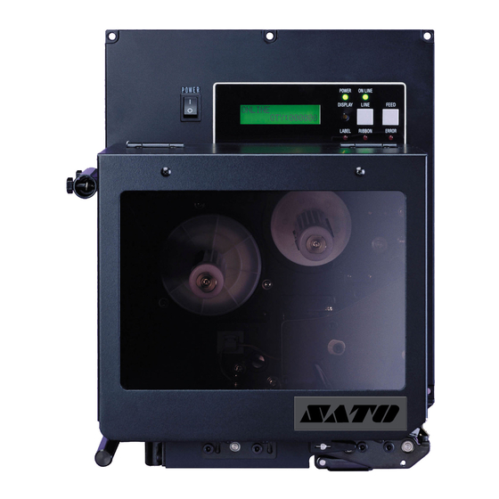
Page 21: Component Names
Ribbon Rewind Ribbon Motion Sensor Cover Open Switch Head Open Switch Ribbon Unwind Label Hold Down Platen Roller Print Head Nip Roller Label Edge Guide Head Pressure Head Latch Latch Adjust M-8460Se/M-8465Se/M-8485Se/M-8490Se M-8459Se Only SATO “Se” Print Engines Page 2-3... -
Page 22: Rear Panel
Type 15A/250V. Interface Slot Slot for installation of Plug-In Interface Module. EXT Connector This is an external signal connector for interfacing with the label applicator system. Memory Card Connectors for Optional PCMCIA Memory Cards. Page 2-4 SATO “Se” Print Engines... -
Page 23: Switches And Sensors
However, models sold in the USA are named according to the direction of label feeding. Thus, Right Hand models feed the label from the left to the right, and Left Hand models load labels from the right to the left. SATO “Se” Print Engines Page 2-5... -
Page 24: Media Loading
Unwind Spindle and push it onto the spindle as far as it will go. Make sure the ribbon wil unwind from the top of the roll. Note that all SATO ribbons are wound face-in (the ink or dull side faces toward the inside of the roll). - Page 25 Make sure the Nip Roller Latch is securely engaged. Note: Always check that the backing paper is taut between Platen Roller and Nip Roller. Nip Roller Peel Nip Roller Label Hold Down Latch Liner SATO “Se” Print Engines Page 2-7...
- Page 26 Section 2. Installation 12. Turn the printer on and press the Feed button. It should feed labels until the first label is peeled and ready for application. Page 2-8 SATO “Se” Print Engines...
-
Page 27: Adjusting The Label Sensor
14 mm to 82 mm 14 mm to 68 mm 14 mm to 68 mm) Non-Print Area 0.12" (3 mm) 0.12" or 0.25" 0.12" (3 mm) 0.12" (3 mm) 3 mm or 6.5 mm SATO “Se” Print Engines Page 2-9... - Page 28 Adjustments to compensate for different liner opacity is done with the LCD panel. Print Head Sensor Adjust Sensor Position (shown open) Slot Screws Page 2-10 SATO “Se” Print Engines...
-
Page 29: Operator Panel
Switches the printer On-Line or Off-Line. It can also be used as a Pause function key to stop label during the printing process. FEED Key To feed one blank label. DISPLAY Potentiometer for adjusting the contrast of the LCD SATO “Se” Print Engines Page 2-11... -
Page 30: Dip Switch Panel
DIP SWITCH PANEL The DIP Switch panel is located inside the cover and contains three 8-position DIP switches and three adjustment potentiometers. Adjustment procedures for these are listed in Section 3: Configuration. DIP Switches Potentiomenters Page 2-12 SATO “Se” Print Engines... -
Page 31: Section 3. Configuration
8 data bits 7 data bits Parity Selection (DSW1-2, DSW1-3). These switches select the type of parity used for error detection. DSW1 DSW1-2 DSW1-3 SETTING No Parity Even Not Used SATO “Se” Print Engines PN 9001073 Rev B Page 3-1... - Page 32 SETTING Therm Direct Therm Sensor Type Selection (DSW2-2). Selects between the use of a label gap or a reflective Eye-Mark detector. See page 2-9 for the location of these sensors. DSW2 DSW2-2 SETTING Eye-Mark Page 3-2 SATO “Se” Print Engines...
- Page 33 M8400S Emulation Mode (DSW2-8). For emulating earlier series software commands. Should be used only if problems are encountered when using existing software. This switch will also affect the settings selected by DSW1-7 and DSW1-8. DSW2 DSW2-8 SETTING Disabled Enabled SATO “Se” Print Engines Page 3-3...
- Page 34 Specifications for a description of the signal level and requirements When DSW3-5 is On, the unit is in the Continuous print mode, Backfeed is disabled and External Signals are ignored. DSW3 DSW3-5 SETTING Enabled Disabled Page 3-4 SATO “Se” Print Engines...
- Page 35 Repeat Print via External Signal (DSW3-8). Allows the applicator to reprint the current label in the print buffer. See Section 6: Interface Specifications for a description of the signal requirements. DSW3 DSW3-8 SETTING Disabled Enabled SATO “Se” Print Engines Page 3-5...
-
Page 36: Default Settings
LCD panel. The printer should be powered off while this message is being displayed (or after the beep is heard. This saves the default settings in the non-volatile memory where they will be automatically loaded the next time the printer is powered on. DEFAULT COMPLETED Page 3-6 SATO “Se” Print Engines... -
Page 37: Potentiometer Adjustments
The amount of backfeed is controlled by the OFFSET potentiometer on the DIP Switch Panel inside the cover. When turned all the way counterclockwise, the amount of backfeed is +3.75 mm, and -3.75 mm when turned all the way counterclockwise. 1. Turn the printer on. SATO “Se” Print Engines Page 3-7... - Page 38 NOTE: The PRINT potentiometer adjustment will affect the darkness in all of the command code speed and darkness ranges. Page 3-8 SATO “Se” Print Engines...
-
Page 39: Lcd Panel Printer Configuration
DSW2-4 ON + POWER ONLINE QTY:000000 Flash Download DSW2-6 ON FLASH DOWNLOAD READY Boot Download DSW2-6 ON + FEED BOOT DOWNLOADER +LINE + POWER PRESS FEED KEY Hidden DSW2-4 ON + FEED HIDDEN MODE + POWER SATO “Se” Print Engines Page 3-9... -
Page 40: Normal Mode
M-8459Se M-8485Se M-8460Se/8465Se M-8490Se 2 ips 4 ips 4 ips 3 ips 6 ips 6 ips 4 ips 8 ips 8 ips 5 ips 10 ips 12 ips Page 3-10 SATO “Se” Print Engines... - Page 41 ABCDEFG label ABCDEFG Leading edge of the label as detected by the sensor Original (0 offset) first line print position ABCDEFG Moved with positive (+) offset to print on trailing edge of label SATO “Se” Print Engines Page 3-11...
- Page 42 5. If you wish to change any of the settings, you CANCEL PRINT JOB must enter the User Settings mode again by COMPLETED taking the printer OFFLINE and pressing the LINE and FEED keys. Page 3-12 SATO “Se” Print Engines...
-
Page 43: Advanced Mode
1. Use the LINE key to step the cursor to either the YES (default) or NO selection. 2. Once the correct setting is selected, pressing the FEED key will accept the setting and advance the display to the Print Offset display. SATO “Se” Print Engines Page 3-13... - Page 44 To set the Calendar, press the LINE key until the cursor is over YES. If the Calendar feature is to be disabled, press the LINE key until the cursor is underneath NO. When the desired setting is selected, press the FEED key. Page 3-14 SATO “Se” Print Engines...
- Page 45 (CRLF ) from the data stream, including graphics and 2D bar codes. It is used primrily to maintain compatibility with earlier models of SATO printers. 1. Use the LINE key to step the underline cusor to either the YES or NO (default) selection.
- Page 46 CC1 or CC2. The default setting is CARD. The menu cycles back to the start screen of the Advanced ADVANCED MODE Mode. To exit this mode, turn the printer OFF and then ON again. Page 3-16 SATO “Se” Print Engines...
-
Page 47: Card Mode
Yes is selected, the printer will enter the Card Copy mode. If No is selected, the display will advance to the Card to Memory SATO Font Copy mode. 2. Confirm your selection by stepping the cursor to the Yes COPY START selection. - Page 48 Section 3. Configuration This selection allows you to copy SATO fonts from the CARD->MEMORYCOPY PCMCIA Memory card installed in the Memory Card slot on SATOFONT the rear of the printer to the optional Flash ROM. 1. Use the LINE key to step the cursor to desired setting. If Yes is selected, the printer will enter the Card Copy mode.
- Page 49 If you select No, the display will return to the previous selection. 3. Once the copy process is completed, press the FEED key MEMORY->CARDCOPY to step the display. COMPLETED SATO “Se” Print Engines Page 3-19...
- Page 50 Yes is selected, the printer will enter the Memory Format mode. If No is selected, the display will advance to the mode display. To exit the Card Mode, power the printer off and then back on. CARD MODE Page 3-20 SATO “Se” Print Engines...
-
Page 51: Service Mode
If the measured values are outside this range, you may have trouble in finding a value that will work properly under all conditions. If this is the case, a higher quality label may be needed to get adequate performance. SATO “Se” Print Engines Page 3-21... - Page 52 5. Once the setting is correct, pressing the FEED key will accept the setting and advance to the Online Feed display. Page 3-22 SATO “Se” Print Engines...
- Page 53 1. Use the LINE key to step the cursor to the desired setting. 2. Once the desired setting is selected, press the FEED key to accept the setting and step to the next display. SATO “Se” Print Engines Page 3-23...
- Page 54 ENABLE DISABLE of its ribbon supply. Use the LINE key to select either option, and then press the FEED key to confirm the selection. Page 3-24 SATO “Se” Print Engines...
-
Page 55: Rfid Mode
Select Yes or No with the LINE key, and the press the FEED key to return to the main Service Mode menu. SATO “Se” Print Engines Page 3-25... - Page 56 100% modulation levels, the press the LINE key to confirm the selection. A higher modulation level results in higher ADVANCED MODE accuracy and detection speeds at the expense of interference levels. Pressing the FEED key returns the user to the Advanced Mode menu. Page 3-26 SATO “Se” Print Engines...
-
Page 57: Test Print Mode
3. Press the FEED key to start printing test labels continuously. 4. Press the FEED key to stop the printer. 5. To exit the Test Print Mode, power the printer off and then back on. SATO “Se” Print Engines Page 3-27... -
Page 58: Default Setting Mode
Alternate protocol codes with the default values. 3. After the default setting is complete, the printer will emit two short beeps indicating the process is complete. 4. To exit the mode, power the printer off and then back on. Page 3-28 SATO “Se” Print Engines... -
Page 59: Download User Defined Protocol Codes
6. If the custom codes are correct, press the FEED key to accept them and terminate the download process. If they are incorrect, turn the printer off without pressing the FEED key and begin the process again. SATO “Se” Print Engines Page 3-29... -
Page 60: Hex Dump Mode
OFFLINE to pause the printing. To resume printing, press QTY:000005 the Line key again. This can be repeated as necessary. To return the printer to normal operation, place DSW2-4 in the OFF position and turn the printer OFF and then back Page 3-30 SATO “Se” Print Engines... -
Page 61: Hidden Mode/Shift Code Operation
ENTER SHIFT NAME selected shift. Finally, define the name of the shift and press the FEED key to exit this mode. Note: this feature is subject to further development. SATO “Se” Print Engines Page 3-31... -
Page 62: Section 4. Cleaning And Maintenance
• Replacing the Fuse ADJUSTING THE PRINT QUALITY One of the nice features of the SATO “Se” printers are their high print quality. They are equipped with two different methods of adjusting the quality of the print: print darkness and speed. When adjusting for optimum print quality, a bar code verifier system should be used. -
Page 63: Print Speed
“smeared” on the trailing edge. CLEANING THE PRINT HEAD, PLATEN AND ROLLERS Supplies needed: SATO SA070 Cleaning Kit (not supplied, check with your dealer) Cleaning the Print Head 1. - Page 64 Print Head Assembly is spring-loaded and will automatically open as soon as the Head Latch is disengaged. 4. Apply SATO Thermal Print Head Cleaner to one of the cotton swabs. 5. The Platen is the rubber roller directly below the Print Head. It should be cleaned of any ribbon or label residue.
-
Page 65: Cleaning The Sensors And Paper End Switch
The Sensor Window is positioned directly below the Upper Sensor. 4. Apply SATO Thermal Print Head Cleaner to one of the cotton swabs. 5. Use the cotton swab to clean any foreign matter from the exposed surface of the sensors. -
Page 66: Replacing The Fuse
3. Unscrew the cap and remove the defective fuse. 4. Replace with a new 250V 15A fuse. 5. Screw the fuse cap back onto the printer and replace the power cable. AC Fuse AC Input Connector Page 4-6 SATO “Se” Print Engines... -
Page 67: Section 5. Programming
INTRODUCTION This section presents a brief overview of the commands that are used with the SATO “Se” printers to produce labels with logos, bar codes and alphanumeric data. The following information is presented in this section: • The SATO Programming Language •... -
Page 68: Selecting Protocol Control Codes
2. If you are using the printer’s RS232C interface, it is necessary to set the COM port on the PC such that the CTS and DSR signals will be ignored. Send your OPEN “COM” statement in the following way: Page 5-2 SATO “Se” Print Engines... - Page 69 30 LPRINT E$;"A"; Sends an “<ESC>A” command code to the LPT1 parallel port 40 LPRINT E$;"H400",E$;"V100";E$;"WL1SATO"; Sends the data “SATO” to be to be placed 400 dots horizontally and 100 dots vertically on the label and printed in the “WL” font.
-
Page 70: The Print Area
The following diagram illustrates the print area for a standard (Right-Hand) M-8485Se and a sample 2 inch wide by 3 inch long label placed within this area. As can be seen, your label will be oriented against the inside right edge of the printer as viewed from the front (label exit) of the printer. - Page 71 Shift Distance = 3.0" x 25.4 mm/in x 8 dpmm = 610 dots Each <ESC>H command would have the value “610” added to it to correctly position each field. SATO “Se” Print Engines Page 5-5...
- Page 72 If you are using a two inch wide label, the entire image may not appear on your label. By adding the following Base Reference Point command to the second line of the data H=50 V=100 SATO V=200 *SATO* *SATO* *SATO* 5" 2" Unshifted Print Area Page 5-6 SATO “Se” Print Engines...
-
Page 73: Rotated Fields
• <ESC>% - The field rotates, but the base reference point for the field remains the same. The following data stream will rotate the print field but will not change the base reference point of the field: <ESC>A<ESC>%1<ESC>V800<ESC>H200<ESC>L0202<ESC>WB1E<E SC>Q1<ESC>Z SATO “Se” Print Engines Page 5-7... -
Page 74: Command Default Settings
(1) The settings for these commands will revert to the default value when the printer receives an <ESC>Z or an <ESC>*. (2) These values transmitted with these commands will remain in effect until a new command is received. Page 5-8 SATO “Se” Print Engines... -
Page 75: Opposite Hand Models
The standard “Se” print engine is referred to as a “right-hand” printer (i.e., when facing the Control Panel, the label comes out from left to right). The M-8485Se, M-8460Se and M-8490Se are also available in a “left-hand” (i.e., the labels comes out right to left) version. -
Page 76: Command Code Page Reference
These examples assume the use of the Standard Protocol Command Codes, with a Right-Hand version of the M-8485Se printer with a parallel interface and a five inch wide label which is the maximum width that will fit in the printer. If the same command stream is sent to an M-8490Se (300dpi) , the image will be reduced by 33% in size. -
Page 77: Section 6. Interface Specifications
The other interfaces available are a high speed (to 57.6K bps) serial interface, an Ethernet interface or an optional Universal Serial Bus (USB) interface. SATO “Se” Print Engines Page 6-1... -
Page 78: The Receive Buffer
With an empty receiving buffer, the status of DTR is “high” (or an X-On status if using X-On/X-Off), meaning the printer is ready to receive data. When the receive buffer is holding 2.0 MB of data (1 MB from being full), DTR Page 6-2 SATO “Se” Print Engines... -
Page 79: Ieee1284 Parallel Interface
IEEE1284 specification must be present to fully utilize the speed capabilities. This interface also operates bi-directionally and can report the status of the printer back to the host. ELECTRICAL SPECIFICATIONS Printer Connector AMP 57-40360 (DDK) or equivalent Cable Connector AMP 57-30360 (DDK) or equivalent SATO “Se” Print Engines Page 6-3... -
Page 80: Data Streams
To Host FAULT To Host Not Used Not Used Logic Gnd Not Used Frame Ground Not Used ( 1 ) +5V (Z=24K ohm) To Host SELECTIN From Host (1) Signals required for IEEE1284 mode. Page 6-4 SATO “Se” Print Engines... -
Page 81: Rs232C Serial Interface
DB-25P (Male), 50 ft. maximum length. For cable configuration, refer to Cable Requirements appropriate to the RS232C protocol chosen. Signal Levels High = +5V to +12V Low = -5V to -12V Pin Assignments Pin 1 Pin 13 Pin 25 Pin 14 SATO “Se” Print Engines Page 6-5... -
Page 82: Ready/Busy Flow Control
Ready/Busy is the hardware flow control method for the serial interface on the Se printers. By raising/lowering the voltage level on Pin 20 of the RS232C port, the printer notifies the host when it is ready to receive data. Pin 4 (RTS) and pin 20 Page 6-6 SATO “Se” Print Engines... -
Page 83: X-On/X-Off Flow Control
USB peripherals using Windows 98. Details for loading the USB driver are contained in the USB Interface Manual that is shipped with each printer with a USB Optional interface installed. Up to 127 devices may be connected to a USB port. SATO “Se” Print Engines Page 6-7... -
Page 84: Local Area Network (Lan) Interface
16 characters, the field will be padded with leading zeroes. If an ENQ is received after the print job specified in the ID bytes has been completed, or there is no data in the buffer, the printer will respond with two “space” characters Page 6-8 SATO “Se” Print Engines... - Page 85 ACK (06 hexadecimal) is returned if there are no errors and a NAK (16 hexadecimal) if a printer error exists. (1) To provide compatibility with older SATO printers, the RS232C interface can be configured to use an earlier Bi-Com 3 ENQ/ACK/NAK protocol selected via DSW2-8 and DSW1-7/8 (on the RS232C Interface module).
- Page 86 Ribbon Near End and Buffer Near Full ( 1 1 Print Stop (without error) OFF-LINE, ERROR CONDITION Head Open Paper End Ribbon End Media Error Sensor Error Head Error Cutter Error Other Error Condition Not supported by legacy Bi-Comprotocols Page 6-10 SATO “Se” Print Engines...
-
Page 87: Status Response
12 ips Print Speed Not Supported Not Supported Not Supported Label Dispense Print mode Reserved Not Supported Not Supported Not Supported Dispense at head position Dispense at dispense position Reserved Not Supported Not Supported Not Supported C SATO “Se” Print Engines Page 6-11... - Page 88 Dispense Offset in dots (0 to 99) 00 to 63 FF to 9D Dispense Offset in dots (-1 to -99) Compatibility Mode Enabled Compatibility Mode Disabled 08 to 40 Not Supported Buzzer Enabled Buzzer Disabled Page 6-12 SATO “Se” Print Engines...
- Page 89 4 byte Sensor Status Word bounded by an STX-ETX pair that reports the values of the printer counters. VALUE DESCRIPTION BYTE NUMBER Reflective Sensor Level Transmissive Sensor Level Out of Paper Paper Present Head Open Head Closed SATO “Se” Print Engines Page 6-13...
- Page 90 VALUE DESCRIPTION BYTE NUMBER Free Font Memory Total Font Memory 9-12 Free Form Overlay Memory 13-16 Total Form Overlay Memory 17-20 Free Graphic Memory 21-24 Total Graphic Memory Page 6-14 SATO “Se” Print Engines...
- Page 91 18 byte Form Overlay Status Word bounded by an STX-ETX pair that reports the Forms downloaded into the printer. VALUE DESCRIPTION BYTE NUMBER 01 to 99 Form Registration Number (ASCII value) 3-18 ASCII Form Name SATO “Se” Print Engines Page 6-15...
- Page 92 Family Attribute Character Set Italic Attribute 79-80 Weight Attribute 81-82 Spread 83-84 Assent in dots 85-86 Registration Start Code 86-87 Registration End Code 88-95 Reserved 96-98 Code 99-100 Horizontal Valid Size 101-102 Left Gap Size Page 6-16 SATO “Se” Print Engines...
- Page 93 No Parity Odd Parity Even Parity 1 Stop Bit 2 Stop Bits Single Item Buffer with Ready/Busy Flow Control Multi-Item Buffer with Ready/Busy Flow Control X-ON/X-OFF Flow Control Status 4 Bi-Comm Status 3 Bi-Comm SATO “Se” Print Engines Page 6-17...
-
Page 94: Pin Assignments
Vcc(pin 13) as illustrated. This will provide a signal level of +5V for a true condition and 0V when a false condition exists.The maximum voltage that can be applied to these pins is +50V and the maximum current they can sink is 500milliamps. Page 6-18 SATO “Se” Print Engines... -
Page 95: Standard Operation
STANDARD OPERATION Start of Print Cycle End of Print Cycle Print Start Input Print Repeat Input Print End Type 1 20 milliseconds Print End Type 2 Print End Type 3 Print End Type 4 SATO “Se” Print Engines Page 6-19... -
Page 96: Repeat Print
Paper/Ribbon ERROR SIGNALS Replinished Head Head Moving Open Closed Print Motion Stopped Paper End Ribbon End Machine Error Print End Type 1 Print End Type 2 Print End Type 3 Print End Type 4 Page 6-20 SATO “Se” Print Engines... -
Page 97: Section 7. Troubleshooting
If so, make sure you are sending data out the correct port. 4. Is the IEEE1284 Interface Module installed in the printer? Older versions of the Parallel Interface module will not work correctly in the “Se” printers. SATO “Se” Print Engines Page 7-1... - Page 98 BASIC, it may be adding these characters automatically as the line wraps. Adding a “width” statement to your program can help to suppress these extra 0D characters by expanding the line length up to 255 Page 7-2 SATO “Se” Print Engines...
-
Page 99: Using The Rs232C Serial Interface
7. From the Hex Dump, if you are seeing extra 0D (CR and LF) characters, and are using BASIC, refer to the beginning of the Command Code section. It provides hints for writing a SATO program in BASIC. SATO “Se” Print Engines Page 7-3... -
Page 100: Using The Universal Serial Bus Interface
3. Click on the Device Manager tab. 4. Make sure that the View Device by type is checked. Scroll down until you get to SATO-USB device. 5. Verify that it does not have any errors next to it. If it shows an error, remove the device and then reinstall it. - Page 101 5. Check the individual protocol troubleshooting sections in provided with the Ethernet Interface Module for additional causes of intermittent printer problems. Intermittent Problems If the print server and the printer start up OK, but you intermittently have problems printing, check the following: SATO “Se” Print Engines Page 7-5...
- Page 102 SET NETWARE RANGE 0. If you are not using NetWare, you can disable NetWare entirely with the command SET NETWARE DISABLED. 2. Check the individual protocol troubleshooting sections provided with the Ethernet Plug-In Interface Module for additional causes of intermittent printer problems. Page 7-6 SATO “Se” Print Engines...
-
Page 103: Error Signals
Error Blinks Media Error 3 Short Media Error Open/close Head Lever Label Blinks Ribbon Blinks None Ribbon Near End Replace ribbon with full roll Line Blinks None Buffer Near Full Slow down transmission rate SATO “Se” Print Engines Page 7-7... - Page 104 Instructions for installing the Memory Card Option are included with the installation kit. Error Handling Memory Card error conditions are indicated to the operator using a combination of the ERROR LED on the front panel and the audible indicator. SATO “Se” Print Engines Page A-1...
-
Page 105: Top Mounted Reflective Sensor
Top Mounted Reflective Sensor Assembly can be installed. This option is not available on the M-8460/8465Se and the Left-Hand versions of the M-8485Se, M-8459Se and M-8490Se. PLUG-IN INTERFACE MODULES The Series “e” printers have user changable Plug-In Interface Modules. The Interface Module is accessible from the Rear Panel and is retained by two screws. - Page 106 5. Replace the two Interface Card Retaining Screws. 6. If the new Interface Module is for a serial interface, set DSW1 for the proper operation. 7. Connect the interface cable to the connector. SATO “Se” Print Engines Page A-3...
- Page 107 Appendix A: Optional Accessories This page left intentionally blank Page A-4 SATO “Se” Print Engines...
Need help?
Do you have a question about the M-8485Se and is the answer not in the manual?
Questions and answers