Table of Contents
Advertisement
S/M No. : R868G7A001
Service Manual
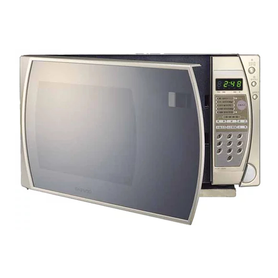
Microwave Oven
:
KOR-868G
Model
• Caution:
In this Manual, some parts can be changed for improving,
their performance without notice in the parts list. So, if you
need the latest parts information, please refer to PPL(Parts
Price List) in Service Information Center (http://svc.dwe.co.kr).
MAY 2007
Advertisement
Table of Contents

Related Manuals for Daewoo KOR-868G


Summary of Contents for Daewoo KOR-868G
-
Page 1: Microwave Oven
S/M No. : R868G7A001 Service Manual Microwave Oven KOR-868G Model • Caution: In this Manual, some parts can be changed for improving, their performance without notice in the parts list. So, if you need the latest parts information, please refer to PPL(Parts Price List) in Service Information Center (http://svc.dwe.co.kr). -
Page 2: Table Of Contents
PRECAUTIONS TO BE OBSERVED BEFORE AND DURING SERVICING TO AVOID POSSIBLE EXPOSURE TO EXCESSIVE MICROWAVE ENERGY (a) Do not operate or allow the oven to be operated with the door open. (b) Make the following safety checks on all ovens to be serviced before activating the magnetron or other micro- wave source, and make repairs if necessary: (1) Interlock operation, (2) Proper door closing, (3) Seal and sealing surfaces (arcing, wear, and other damage), (4) Damage to or loosening of hinges and latches, (5) Evidence of dropping or abuse. -
Page 3: Safety And Precautions
SAFETY AND PRECAUTIONS CAUTION This device is to be Serviced only by Properly Qualified Service Personel. Consult the Service Manual for Proper Service Procedures to Assure Continued Safety Operation and for Precautions to be Taken to Avoid Possible Exposure to Excessive Microwave Energy. 1. -
Page 4: Specifications
SPECIFICATIONS MODEL KOR-868G7A27 POWER SUPPLY 120V~60Hz, SINGLE PHASE WITH GROUNDING MICROWAVE 1350W POWER GRILL CONSUMPTION COMBINATION MICROWAVE ENERGY OUTPUT 900W MICROWAVE FREQUENCY 2450MHz OUTSIDE DIMENSIONS (W X H X D) 495 x 294 x 388 mm (19.5 x 11.6 x 15.3 in) CAVITY DIMENSIONS (W X H X D) 320 x 228 x 388 mm (12.6 x 9.0 x 13.3 in) NET WEIGHT... -
Page 5: External View
EXTERNAL VIEW 1. OUTER DIMENSION... -
Page 6: Feature Diagram
2. FEATURE DIAGRAM 1. DOOR SEAL Door seal maintains the microwave within the oven cavity and prevents microwave leakage. 2. DOOR HOOK When the door is closed, it will automatically lock shut. If door is opened while oven is operating, magnetron tube will immediately stop operating. -
Page 7: Control Panel
3. CONTROL PANEL DISPLAY – Cooking time, power level, present time are displayed. AUTO COOK – Used to cook using a program or to reheat. AUTO DEFROST – Used to defrost foods.(by weight) POWER – Used to set power level. DEFROST –... -
Page 8: Installation
INSTALLATION 1. Steady, flat location. This microwave oven should be set on a steady, flat surface. 2. Leave space behind and side. All air vents should be kept a clearance. If all vents are covered during operation, the oven may be overheated and, eventually, cause oven failure. -
Page 9: Operations And Functions
OPERATIONS AND FUNCTIONS 1. Connect the mains lead to an electrical outlet. 2. After placing the food in a suitable container, open the oven door and put it on the glass tray. The glass tray must always be in place during cooking. 3. -
Page 10: Disassembly And Assembly
DISASSEMBLY AND ASSEMBLY Cautions to be observed when troubleshooting. Unlike many other appliances, the microwave oven is high-voltage, high-current equipment. It is completely safe during normal operation. However, carelessness in servicing the oven can result in an electric shock or possible danger from a short circuit. You are asked to observe the following precautions carefully. - Page 11 1. To remove cabinet 1) Remove three screws on cabinet back. 2) Push the cabinet backward. 2. To remove door assembly 1) Remove two screws which secure the stopper hinge top. 2) Remove the door assembly from top plate of cavity. 3) Reverse the above for reassembly.
- Page 12 3. To remove door parts. REF NO. PART CODE PART NAME DESCRIPTION Q’TY REMARK 3512207900 FRAME DOOR ABS SG-175 SG-0760D 2TE16A27CL DOUBLE TAPE 0.16T X 27MM CLEAR 550M 3517008200 BARRIER-SCREEN*O SAN T1.5 3515204100 STOPPER HINGE*T AS KOR-63150S 3511711800 DOOR PAINTING AS KOR-866T0S 3517006000 BARRIER-SCREEN*I...
- Page 13 (1) Remove the gasket door from door painting as. (2) Remove the barrier screen inner from door painting as. (3) Remove the door frame from door painting as. (4) Remove the stopper hinge top from door painting as. (5) Remove the spring and the hook. (6) Remove the supporter barrier screen outer from door frame.
- Page 14 5. To remove control panel parts. REF NO. PART CODE PART NAME DESCRIPTION Q’TY REMARK 3516911300 BUTTON DOOR OPEN ABS SG-175, SG-0760D 3518522240 MEMBRANE KOR-868G7S 441G430171 SPRING BUTTON SWP DIA 0.7 3516729700 CONTROL PANEL ABS SG-175 SG-0760D 3516911100 BUTTON FUNCTION-A ABS SG-175 SG-0760D PKMPMSAQ20 MAIN PCB AS...
- Page 15 6. To remove high voltage capacitor. 1) Remove a screw which secure the grounding ring terminal of the H.V. diode and the capacitor holder. 2) Remove the H.V. diode from the capacitor holder. 3) Reverse the above steps for reassembly. High voltage circuit wiring 7.
- Page 16 8. To remove wind guide assembly. 1) Remove a screw which secure the wind guide assembly. 2) Draw forward the wind guide assembly. 3) Pull the fan from the motor shaft. 4) Remove two screws which secure the motor shaded pole. 5) Remove the motor shaded pole.
-
Page 17: Interlock Mechanism And Adjustment
INTERLOCK MECHANISM AND ADJUSTMENT The door lock mechanism is a device which has been specially designed to completely eliminate microwave radiation when the door is opened during operation, and thus to perfectly prevent the danger resulting from the leakage of microwave. WH/BK RD/RD BK/BL... -
Page 18: Troubleshooting Guide
TROUBLESHOOTING GUIDE Following the procedure below to check if the oven is defective or not. 1. Check grounding before trouble checking. 2. Be careful of the high voltage circuit. 3. Discharge the high voltage capacitor. 4. When checking the continuity of the switches, fuse or high voltage transformer, disconnect one lead wire from these parts and check continuity with the AC plug removed. - Page 19 CONDITION CHECK RESULT CAUSE REMEDY Replace Defective mag- Outlet has Check continuity of magnetron Continuity netron proper volt- age Fuse does not Replace blow. Open power sup- Check continuity of Continuity ply cord power supply cord Replace Normal Defective touch control circuit Replace Display do not shown...
- Page 20 (TROUBLE 3) No microwave oscillation even though fan motor rotates. CONDITION CHECK RESULT CAUSE REMEDY Continuity Replace Check continuity of high Defective high microwave voltage capacitor terminals voltage trans- oscillation with wires removed former Continuity in Replace Check continuity of high voltage Defective high backward rectifier in forward and backward...
- Page 21 (TROUBLE 4) The following visual conditions indicate a probable defective touch control circuit or membrane switch assembly. 1. Incomplete segments (1) Segments missing (2) Partical segments missing (3) Digit flickering other than normal display slight flickering (4) “ :0” does not display when power is on. 2.
-
Page 22: Measurement And Test
MEASUREMENT AND TEST 1. MEASUREMENT OF THE MICROWAVE POWER OUTPUT Microwave output power can be checked by indirectly measuring the temperature rise of a certain amount of water exposed to the microwave as directed below. PROCEDURE 1. Microwave power output measurement is made with the microwave oven supplied at rated voltage and operated at its maximum microwave power setting with a load of 1000±5cc of potable water. -
Page 23: Microwave Radiation Test
2. MICROWAVE RADIATION TEST CAUTION : 1. Make sure to check the microwave leakage before and after repair of adjustment. 2. Always start measuring of an unknown field to assure safety for operating personnel from microwave energy. 3. Do not place your hands into any suspected microwave radiation field unless the safe density level is known. 4. -
Page 24: Component Test Procedure
3. COMPONENT TEST PROCEDURE • High voltage is present at the high voltage terminal of the high voltage transformer during any cooking cycle. • It is neither necessary nor advisable to attempt measurement of the high voltage. • Before touching any oven components or wiring, always unplug the oven from its power source and discharge the capacitor. -
Page 25: Wiring Diagram
WIRING DIAGRAM... -
Page 26: Printed Circuit Board
PRINTED CIRCUIT BOARD 1. CIRCUIT CHECK PROCEDURE 1. Low Voltage Transformer check • The low voltage transformer is located on the P.C.B. • Measuring condition: input voltage : 120V/Frequency : 60Hz Terminal Voltage LOAD NO LOAD AC 25.8 V AC 28.4 V NOTE : 1. - Page 27 Measure Point...
- Page 28 3. When there is no microwave oscillation 1) When touching the START pad, oven lamp does not turn on. Fan motor do not rotate, but cook indicator in display comes on. * Cause : RELAY 2 does not operate. refer to Circuit Diagram (Point 3) - Check method POINT STATE...
-
Page 29: Pcb Circuit Diagram
2. PCB CIRCUIT DIAGRAM... -
Page 30: Location No
3. P.C.B. LOCATION NO. NAME SYMBOL SPECIFICATION PART CODE Q'TY BUZZER BM-20K 3515600100 C ARRAY 7P(6) 102 M 50V CN6XB-102M CAPACITOR ELEC 50V RS IMF CEXE1H109A CAPACITOR ELEC 25V RSS 1000uF DEZF1E102V CONNECTOR WAFER YW396-02V 3519150520 CONNECTOR FILM FCZ254-11 441M367160 CONNECTOR WAFER YW396-05V 3519150510... -
Page 31: Exploded View And Parts List
EXPLODED VIEW AND PARTS LIST 1. DOOR ASSEMBLY Refer to Disassembly and assembly. 2. CONTROL PANEL ASSEMBLY Refer to Disassembly and assembly. 3. TOTAL ASSEMBLY... - Page 32 PART CODE PART NAME DESCRIPTION Q'TY REMARK 3511710720 DOOR AS KOR-86050S PKCPSWNF10 CONTROL-PANEL AS KOR-860A1A 3510805400 CABINET AS KOR-81150S 7272400811 SCREW TAPTITE TT3 TRS 4X8 MFZN 3516109900 CAVITY AS KOR-86150S 7122401211 SCREW TAPPING T2S TRS 4X12 MFZN 7121300611 SCREW TAPPING T2S PAN 3X6 MFZN 3518902600 THERMOSTAT...
- Page 33 DAEWOO ELECTRONICS CORP. 686, AHYEON-DONG MAPO-GU SEOUL, KOREA C.P.O. BOX 8003 SEOUL, KOREA TELEX: DWELEC K28177-8 CABLE: “DAEWOOELEC” S/M NO. : R868G7A001 PRINTED DATE: SPET.2006...
Need help?
Do you have a question about the KOR-868G and is the answer not in the manual?
Questions and answers