ASROCK Vision HT Series User Manual
Hide thumbs
Also See for Vision HT Series:
- User manual (58 pages) ,
- Installation and configuration manual (11 pages) ,
- Installation manual (4 pages)

Related Manuals for ASROCK Vision HT Series


Summary of Contents for ASROCK Vision HT Series
-
Page 1: User Manual
Vision HT Series User Manual Version 1.0 Published October 2013 Copyright©2013 ASRock INC. All rights reserved. -
Page 2: Copyright Notice
(including damages for loss of proits, loss of business, loss of data, interruption of business and the like), even if ASRock has been advised of the possibility of such damages arising from any defect or error in the documentation or product. - Page 3 he terms HDMI™ and HDMI High-Deinition Multimedia Interface, and the HDMI logo are trademarks or registered trademarks of HDMI Licensing LLC in the United States and other countries. Manufactured under license under U.S. Patent Nos: 5,956,674; 5,974,380; 6,487,535; 7,003,467 & other U.S. and worldwide patents issued & pending. DTS, the Symbol, & DTS and the Symbol together is a registered trademark &...
-
Page 4: Safety Instructions
Safety instructions Your system is designed and tested to meet the latest standards of safety for information technology equipment. However, to ensure your safety, it is important that you read the fol lowing safety instructions. Setting up your system • Read and follow all instructions in the documentation before you operate your system. -
Page 5: Installation Notices
Safety cautions and warnings Optical Drive Safety Information Optical drives sold with this system contains a CLASS 1 LASER PRODUCT. CAUTION: Invisible laser radiation when open. Do not stare into beam or view directly with optical instruments. WARNING: Making adjustments or performing procedures other than those speciied in the user’s manual may result in hazardous laser exposure. -
Page 6: Table Of Contents
Contents Chapter 1 Introduction Speciications System Motherboard Components Rear Panel System Chassis MHSL (Mobile High Speed Link ) Remote Controller Chapter 2 Opening the chassis Chapter 3 Reinstalling the ODD/HDD Chapter 4 Installing the second HDD Chapter 5 Reinstalling the DIMMs Chapter 6 Reinstalling the CPU Chapter 7 Dual Monitor Chapter 8 Software and Utilities Operation... - Page 7 Chapter 9 UEFI SETUP UTILITY Introduction 9.1.1 UEFI Menu Bar 9.1.2 Navigation Keys Main Screen OC Tweaker Screen Advanced Screen 9.4.1 CPU Coniguration 9.4.2 Chipset Coniguration 9.4.3 Storage Coniguration 9.4.4 Intel® Rapid Start Technology 9.4.5 Intel® Smart Connect Technology 9.4.6 Super IO Coniguration 9.4.7 ACPI Coniguration 9.4.8 USB Coniguration Tools...
-
Page 8: Chapter 1 Introduction
ASRock’s website without further notice. If you require technical support related to this product, please visit our website for speciic information about the model you are using. ASRock website http:// www.asrock.com. -
Page 9: Speciications
1.2 Speciications • Intel® Mobile Haswell Processor. Processor • Supports 4 Generation Intel® Corei7/i5/i3 Dual-Core Mobile Haswell Processor Family • Mobile Intel® HM87 Express chipset Chipset • Supports DDR3 1600/1333/1066MHz, 2xSO-DIMM slots, Memory maximum up to 16GB • Intel® HD Graphics Display *Intel®... - Page 10 Vision HT Series • Bluetooth 4.0/3.0 HS class II Bluetooth • Support MCE function Remote Controller • 90W/19V Adapter Power • 200mm(W)x70mm(H)x200mm(L) Dimen- sion • 2.8L Volume *For barebone systems, CPU, memory, HDDs and ODDs may not be included. Free bundle sotware:...
- Page 11 VGA resolution: Maximum Resolution Maximum Resolution Display 1 Display 2 Display 1 Display 2 4096x2304 @ 24Hz HDMI 1920x1200 @ 60Hz 2560x1600 @ 60Hz 4096x2304 @ 24Hz HDMI 1920x1200 @ 60Hz 2560x1600 @ 60Hz...
-
Page 12: System Motherboard Components
Vision HT Series 1.3 System Motherboard Components mSATA DDR3_A1 DDR3_B1 No. Description SATA 3.0 connector: For HDD SATA data cables SATA 3.0 connector: For HDD SATA data cables ATX5V output power connector for slim ODD & 2.5” HDD SATA connector: For ODD SATA data cables... - Page 13 NOTE 1. SATA and Power Connections Connect to ODD SATA & Power Connections Connect to SATA Connector (4) Connect to HDD Connect to ATX5V Power Connector (3) Connect to SATA Connector (1) 2. Fan Connection Fan connector Rotation +12V Ground...
-
Page 14: Rear Panel
Vision HT Series 1.4 Rear Panel No. Description HDMI connector eSATA2 connector DVI-I port USB3.0 ports: USB devices Mic In (Pink): Microphone Optical S/PDIF Out port DC-In jack Side port for side speakers Center/LFE (Orange): Center / subwoofer speakers Front L/R Out (Lime): Stereo speakers or headphones Line In (Blue) for 2/4/6 channel;... -
Page 15: System Chassis
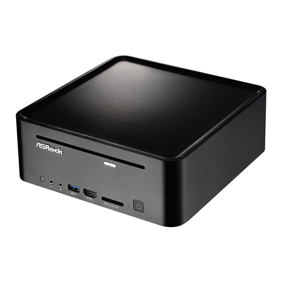
1.5 System Chassis No. Description Headphone Microphone USB3.0 ports: USB devices MHSL port 4-in-1 Card reader (MMC/SD3.0/MS/MS Pro) Power ON/OFF button with status indicator Slot-in Optical Disc Drive... -
Page 16: Mhsl (Mobile High Speed Link )
Not only does it support the MHL standard’s features such as charging while browsing the portable device’s content on another monitor, MHSL also lets users sync data between the mobile device and your PC, plus it supports ASRock’s HDMI-In feature so that other devices that support HDMI output may work through the MHSL port too. - Page 17 Step 1 Connect your monitor to the HDMI port on the system via an HDMI cable. Step 2 Connect your mobile device to the MHSL port on the system via the MHSL to Micro USB Cable. Step 3 Double-click the “A-Tuning“ icon on the desktop and ind "MHSL / HDMI-In"...
-
Page 18: Remote Controller
Vision HT Series 1.7 Remote Controller Some remote controller functions listed above are only available with the relative hardware equipments. If the hardware equipments you adopt are not compatible with the system, you are not allowed to use these functions. his product is designed to meet MCE standards. -
Page 19: Chapter 2 Opening The Chassis
Chapter 2 Opening the chassis 1. Press the button on the rear I/O to open the top side of the chassis. 2. Ater the chassis is opened, you will see the top shield inside the chassis. 3. Unscrew the screws on the corners of the top shield. 4. -
Page 20: Chapter 3 Reinstalling The Odd/Hdd
Vision HT Series Chapter 3 Reinstalling the ODD/HDD 1. Ater you remove the top shield, you will see the ODD/HDD bracket. 2. Disconnect the ODD/HDD SATA power cable, and take out the ODD/HDD bracket. 3. Unscrew the screws from the side of the ODD / HDD rack, and change your... -
Page 21: Chapter 4 Installing The Second Hdd
Chapter 4 Installing the second HDD 1. Please follow steps 1 to 3 on page 15 to remove the ODD and the irst HDD in advance. hen install the second HDD and fasten the screws to the rack. 2. Place the irst HDD to the rack and fasten the screws from both sides. 3. - Page 22 Vision HT Series 4. Connect one end of the SATA and power cables to the HDDs and the other end to SATA3_1 or SATA3_2 connectors on the motherboard. 5. Connect one end of the SATA and power cables to the ODD and the other end to SATA2_1 and J1 connectors on the motherboard.
-
Page 23: Chapter 5 Reinstalling The Dimms
Chapter 5 Reinstalling the DIMMs 1. Unlock the DIMM slot by pressing the retaining clips outward to change the DIMM. -
Page 24: Chapter 6 Reinstalling The Cpu
Vision HT Series Chapter 6 Reinstalling the CPU *Torx T8 screwdriver is required for the installation. 1. Unscrew the screws of the CPU fan. 2. Rotate the screw on the top of the CPU socket. 3. Now you can reinstall a new CPU to the system. -
Page 25: Chapter 7 Dual Monitor
Chapter 7 Dual Monitor ASRock Vision HT Series HTPC supports dual monitor. With the internal VGA output which supports DVI-I and HDMI, you can easily enjoy the beneits of dual monitor. ASRock Vision HT Series HTPC also provides independent display controllers for DVI-I and HDMI to support dual VGA output so that DVI-I and HDMI can drive the same or diferent display contents simultaneously. -
Page 26: Chapter 8 Software And Utilities Operation
Vision HT Series Chapter 8 Software and Utilities Operation 8.1 Installing Drivers he Support CD that comes with this system contains necessary drivers and useful utilities that enhance the system’s features. Running The Support CD To begin using the support CD, insert the CD into your CD-ROM drive. he CD automatically displays the Main Menu if “AUTORUN”... -
Page 27: A-Tuning
8.2 A-Tuning A-Tuning is ASRock’s multi purpose sotware suite with a new interface, more new features and improved utilities, including XFast RAM, Dehumidiier, Good Night LED, FAN-Tastic Tuning and a whole lot more. 8.2.1 Installing A-Tuning When you install the all-in-one driver to your system from ASRock’s support CD, A-Tuning will be auto-installed as well. - Page 28 Vision HT Series Tools Various tools and utilities. XFast RAM Boost the system’s performance and extend the HDD’s or SSD’s lifespan! Create a hidden partition, then assign which iles should be stored in the RAM drive. XFast LAN Boost the speed of your internet connection! Select a speciic mode for making the designated program's priority highest.
-
Page 29: System Info
FAN-Tastic Tuning Conigure up to ive diferent fan speeds using the graph. he fans will automatically shit to the next speed level when the assigned temperature is met. Dehumidiier Prevent motherboard damages due to dampness. Enable this function and conigure the period of time until the computer powers on, and the duration of the dehumidifying process. -
Page 30: Chapter 9 Uefi Setup Utility
Chapter 9 UEFI SETUP UTILITY 9.1 Introduction ASRock Interactive UEFI is a blend of system coniguration tools, cool sound efects and stunning visuals. Not only will it make BIOS setup less diicult but also a lot more amusing. his section explains how to use the UEFI SETUP UTILITY to conigure your system. -
Page 31: Navigation Keys
9.1.2 Navigation Keys Use < > key or < > key to choose among the selections on the menu bar, and use < > key or < > key to move the cursor up or down to select items, then press <Enter>... -
Page 32: Main Screen
When you enter the UEFI SETUP UTILITY, the Main screen will appear and display the system overview. Active Page on Entry Select the default page when entering the UEFI setup utility. UEFI Guide UEFI Guide is a quick tutorial for ASRock's UEFI setup Utility. You may abort the tutorial by pressing "esc". -
Page 33: Oc Tweaker Screen
9.3 OC Tweaker Screen In the OC Tweaker screen, you can set up overclocking features. Because the UEFI sotware is constantly being updated, the following UEFI setup screens and descriptions are for reference purpose only, and they may not exactly match what you see on your screen. -
Page 34: Intel Turbo Boost Technology
Vision HT Series CPU Coniguration CPU Ratio he CPU speed is determined by the CPU Ratio multiplied with the BCLK. Increasing the CPU Ratio will increase the internal CPU clock speed without afecting the clock speed of other components. CPU Cache Ratio he CPU Internal Bus Speed Ratio. - Page 35 Short Duration Power Limit Conigure Package Power Limit 2 in watts. When the limit is exceeded, the CPU ratio will be lowered immediately. A lower limit can protect the CPU and save power, while a higher limit may improve performance. Primary Plane Current Limit Conigure the current limit of the CPU under Turbo Mode in ampere.
- Page 36 Vision HT Series DRAM Coniguration DRAM Tweaker Fine tune the DRAM settings by leaving marks in checkboxes. Click OK to conirm and apply your new settings. CAS# Latency (tCL) he time between sending a column address to the memory and the beginning of the data in response.
- Page 37 Command Rate (CR) he delay between when a memory chip is selected and when the irst active command can be issued. Write Recovery Time (tWR) he amount of delay that must elapse ater the completion of a valid write operation, before an active bank can be precharged.
- Page 38 Vision HT Series tRDRDDR Conigure between module read to read delay from diferent ranks. tRDRDDD Use this to change DRAM tRWSR Auto/Manual settings. he default is [Auto]. tWRRD Conigure between module write to read delay. tWRRDDR Conigure between module write to read delay from diferent ranks.
- Page 39 IO-L (CHA) Conigure IO latency for channel A. IO-L (CHB) Conigure IO latency for channel B. ODT WR (CHA) Conigure the memory on die termination resistors' WR for channel A. ODT WR (CHB) Conigure the memory on die termination resistors' WR for channel B. ODT NOM (CHA) Use this to change ODT (CHA) Auto/Manual settings.
- Page 40 Vision HT Series CPU Cache Override Voltage Add voltage to the CPU Cache when the system is under heavy load. CPU Cache Voltage Ofset Conigure the voltage for the CPU Cache. Setting the voltage higher may increase system stability when overclocking.
-
Page 41: Advanced Screen
9.4 Advanced Screen In this section, you may set the conigurations for the following items: CPU Coniguration, Chipset Coniguration, Storage Coniguration, Intel® Rapid Start Technology, Intel® Smart Connect Technology, Super IO Coniguration, ACPI Coniguration and USB Coniguration. Setting wrong values in this section may cause the system to malfunction. -
Page 42: Cpu Coniguration
Vision HT Series 9.4.1 CPU Coniguration Intel Hyper Threading Technology Intel Hyper hreading Technology allows multiple threads to run on each core, so that the overall performance on threaded sotware is improved. Active Processor Cores Select the number of cores to enable in each processor package. - Page 43 Package C State Support Enable CPU, PCIe, Memory, Graphics C State Support for power saving. CPU Thermal Throttling Enable CPU internal thermal control mechanisms to keep the CPU from overheat- ing. No-Execute Memory Protection Processors with No-Execution Memory Protection Technology may prevent certain classes of malicious bufer overlow attacks.
-
Page 44: Chipset Coniguration
Vision HT Series 9.4.2 Chipset Coniguration Share Memory Conigure the size of memory that is allocated to the integrated graphics processor when the system boots up. Render Standby Power down the render unit when the GPU is idle for lower power consumption. - Page 45 Good Night LED By enabling Good Night LED, the Power/LAN LEDs will be switched of when the system is on. It will also automatically switch of the Power and Keyboard LEDs when the system enters into Standby/Hibernation mode. HDMI-IN Compatible Mode Enable HDMI-IN Compatible Mode if the HDMI-In port encounters compatibility issues.
-
Page 46: Storage Coniguration
Vision HT Series 9.4.3 Storage Coniguration SATA Controller(s) Enable/disable the SATA controllers. SATA Mode Selection IDE: For better compatibility. AHCI: Supports new features that improve performance. RAID: Combine multiple disk drives into a logical unit. AHCI (Advanced Host Controller Interface) supports NCQ and other new features that will improve SATA disk performance but IDE mode does not have these advan- tages. - Page 47 Hard Disk S.M.A.R.T. S.M.A.R.T stands for Self-Monitoring, Analysis, and Reporting Technology. It is a monitoring system for computer hard disk drives to detect and report on various indicators of reliability.
-
Page 48: Intel® Rapid Start Technology
Vision HT Series 9.4.4 Intel® Rapid Start Technology ® Intel Rapid Start Technology Intel® Rapid Start Technology is a new zero power hibernation mode which allows users to resume in just 5-6 seconds. -
Page 49: Intel® Smart Connect Technology
9.4.5 Intel® Smart Connect Technology ® Intel Smart Connect Technology ® Intel Smart Connect Technology automatically updates your email and social networks, such as Twitter, Facebook, etc. while the computer is in sleep mode. -
Page 50: Super Io Coniguration
Vision HT Series 9.4.6 Super IO Coniguration CIR Controller Enable or disable the CIR Receiver for Remote Controller. -
Page 51: Acpi Coniguration
9.4.7 ACPI Coniguration Suspend to RAM It is recommended to select auto for ACPI S3 power saving. Check Ready Bit Enable to enter the operating system ater S3 only when the hard disk is ready, this is recommended for better system stability. ACPI HPET Table Enable the High Precision Event Timer for better performance and to pass WHQL tests. - Page 52 Vision HT Series USB Keyboard/Remote Power On Allow the system to be waked up by an USB keyboard or remote controller. USB Mouse Power On Allow the system to be waked up by an USB mouse.
-
Page 53: Usb Coniguration
9.4.8 USB Coniguration Intel USB 3.0 Mode Enable or disable all the USB 3.0 ports. It is recommended to select [Smart Auto]. Legacy USB 3.0 Support Enable or disable Legacy OS Support for USB 3.0 devices. -
Page 54: Tools
In order to prevent users from bypassing OMG, guest accounts without permission to modify the system time are required. UEFI Tech Service Contact ASRock Tech Service if you are having trouble with your PC. Please setup network coniguration before using UEFI Tech Service. Easy RAID Installer Easy RAID Installer helps you to copy the RAID driver from the support CD to your USB storage device. - Page 55 Save UEFI iles in your USB storage device and run Instant Flash to update your UEFI. Internet Flash ASRock Internet Flash downloads and updates the latest UEFI irmware version from our servers for you. Please setup network coniguration before using Internet Flash.
- Page 56 Vision HT Series Dehumidiier Period Conigure the period of time until the computer powers on and enables Dehumidiier ater entering S4/S5 state. Dehumidiier Duration Conigure the duration of the dehumidifying process before it returns to S4/S5 state. Dehumidiier CPU Fan Setting Conigure the speed of the CPU fan while Dehumidiier is enabled.
-
Page 57: Hardware Health Event Monitoring Screen
9.6 Hardware Health Event Monitoring Screen his section allows you to monitor the status of the hardware on your system, including the parameters of the CPU temperature, motherboard temperature, fan speed and voltage. CPU Fan 1 Setting Select a fan mode for CPU Fans 1, or choose Customize to set 5 CPU temperatures and assign a respective fan speed for each temperature. -
Page 58: Boot Screen
Vision HT Series 9.7 Boot Screen his section displays the available devices on your system for you to conigure the boot settings and the boot priority. Fast Boot Fast Boot minimizes your computer's boot time. In fast mode you may not boot from an USB storage device. - Page 59 Full Screen Logo Enable to display the boot logo or disable to show normal POST messages. AddOn ROM Display Enable AddOn ROM Display to see the AddOn ROM messages or conigure the AddOn ROM if you've enabled Full Screen Logo. Disable for faster boot speed. Boot Failure Guard If the computer fails to boot for a number of times the system automatically restores the default settings.
- Page 60 Vision HT Series Launch Storage OpROM Policy Select UEFI only to run those that support UEFI option ROM only. Select Legacy only to run those that support legacy option ROM only. Launch Video OpROM Policy Select UEFI only to run those that support UEFI option ROM only. Select Legacy...
-
Page 61: Security Screen
9.8 Security Screen In this section you may set or change the supervisor/user password for the system. You may also clear the user password. Supervisor Password Set or change the password for the administrator account. Only the administrator has authority to change the settings in the UEFI Setup Utility. Leave it blank and press enter to remove the password. -
Page 62: Exit Screen
Vision HT Series 9.9 Exit Screen Save Changes and Exit When you select this option the following message, “Save coniguration changes and exit setup?” will pop out. Select [OK] to save changes and exit the UEFI SETUP UTILITY. Discard Changes and Exit When you select this option the following message, “Discard changes and exit... -
Page 63: Contact Information
Contact Information If you need to contact ASRock or want to know more about ASRock, you’re welcome to visit ASRock’s website at http://www.asrock.com; or you may contact your dealer for further information. For technical questions, please submit a support request form at http://www.asrock.com/support/tsd.asp...
Need help?
Do you have a question about the Vision HT Series and is the answer not in the manual?
Questions and answers