Table of Contents
Advertisement
Advertisement
Table of Contents

Related Manuals for ASROCK DESKMINI SERIES


Summary of Contents for ASROCK DESKMINI SERIES
-
Page 2: Copyright Notice
(including damages for loss of profits, loss of business, loss of data, interruption of business and the like), even if ASRock has been advised of the possibility of such damages arising from any defect or error in the documentation or product. - Page 3 The terms HDMI™ and HDMI High-Definition Multimedia Interface, and the HDMI logo are trademarks or registered trademarks of HDMI Licensing LLC in the United States and other countries.
-
Page 4: Table Of Contents
Installing Memory Modules (SO-DIMM) Installing the WiFi Module Installing the M.2 SSD (Type 2280) Installing the 2.5-inch HDD/SSD Complete Installing the VESA Bracket (Optional) Chapter 3 Software and Utilities Operation Installing Drivers ASRock Live Update & APP Shop 3.2.1 UI Overview... - Page 5 3.2.2 Apps 3.2.3 BIOS & Drivers 3.2.4 Setting Enabling USB Ports for Windows® 7 Installation Chapter 4 UEFI SETUP UTILITY Introduction EZ Mode Advanced Mode 4.3.1 UEFI Menu Bar 4.3.2 Navigation Keys Main Screen OC Tweaker Screen Advanced Screen 4.6.1 CPU Configuration 4.6.2 Chipset Configuration 4.6.3 Storage Configuration 4.6.4 Super IO Configuration...
-
Page 6: Chapter 1 Introduction
In case any modifications of this documentation occur, the updated version will be available on ASRock’s website without further notice. If you require technical support related to this product, please visit our website for specific information about the model you are using. -
Page 7: Specifications
Generation Intel® Core i7/i5/i3/Pentium®/ Celeron® Processors (Max. TDP 65W) CPU cooling • Supports Standard Intel Box Fan Coolers Mother- • ASRock H110M-STX (Mini-STX) board Chipset • Intel® H110 Intel® H170 Chipset (Optional); Intel® Q170 Chipset (Optional); Intel® B150 Chipset (Optional) Graphics • Intel®... - Page 8 Operation • 0~35°C Temp. * For detailed product information, please visit our website: http://www.asrock.com Please realize that there is a certain risk involved with overclocking, including adjusting the setting in the BIOS, applying Untied Overclocking Technology, or using third-party overclocking tools. Overclocking may affect your system’s stability, or even cause damage to the components and devices of your system.
-
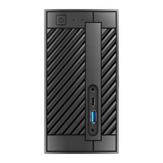
Page 9: Chapter 2 Product Overview
Chapter 2 Product Overview This chapter provides diagrams showing the location of important components of the Beebox series. 2.1 Front View Description Power Button Power LED HDD LED MIC-In USB 3.0 Type-A Port USB 3.0 Type-C Port Headphone/Headset... -
Page 10: Rear View
DeskMini series 2.2 Rear View Description DC Jack (Supports 19V 120W Power Adapters) Display Port HDMI Port D-Sub Port USB 3.0 Port LAN RJ-45 Port* Key Lock Kensington Lock USB 2.0 Port * There are two LEDs on the LAN port. Please refer to the table below for the LAN port LED indications. -
Page 11: Motherboard Layout
2.3 Motherboard Layout Top View H110M-STX CPU_FAN2 RoHS DC Jack CPU_FAN1 LPC1 SPEAKER1 USB_5_6 COM1 Audio CODEC Mic In USB 3.0 USB_2 PANEL1 PLED PWRBTN USB 3.0 BIOS HDLED RESET USB_1 Intel USB 2.0 Top: T: USB3 H110 RJ-45 USB 3.0 Headphone B: USB4 / Headset... -
Page 12: Bottom View
DeskMini series Bottom View CMOS Battery SATA3 SATA3... - Page 13 No. Description 5-Pin CPU Fan Connector (CPU_FAN2) 2 x 260-pin DDR4 SO-DIMM Slots (DDR4_A1, DDR4_B1) 4-Pin CPU Fan Connector (CPU_FAN1) LPC Debug Header (LPC1) USB 2.0 Header (USB_5_6) Internal Speaker Header (SPEAKER1) COM Port Header (COM1) (Optional) System Panel Header (PANEL1) Chassis Intrusion Header (CI1) SATA3 Connector (SATA1) SATA3 Connector (SATA2)
-
Page 14: Onboard Headers And Connectors
DeskMini series Onboard Headers and Connectors Onboard headers and connectors are NOT jumpers. Do NOT place jumper caps over these headers and connectors. Placing jumper caps over the headers and connectors will cause permanent damage to the motherboard. System Panel Header... - Page 15 Internal Speaker Header Please connect the chassis Front_L- speaker to this header. (4-pin SPEAKER1) Front_L+ Front_R+ (see p.6, No. 6) Front_R- Serial ATA3 Connectors These two SATA3 (see p.7, No. 10 and 11) connectors support SATA data cables for internal storage devices with up to Signal Name Signal Name...
- Page 16 DeskMini series CPU Fan Connector This motherboard (5-pin CPU_FAN2) provides a 5-Pin CPU fan (see p.6, No. 1) connector. This connector supports Intel® 1L Thermal FAN_VOLTAGE Modules. FAN_SPEED FAN_SPEED_CONTROL Serial Port Header This COM1 header (Optional) supports a serial port (9-pin COM1) module.
-
Page 17: Chapter 3 Hardware Installation
Chapter 3 Hardware Installation 3.1 Begin Installation 1. Unscrew the four screws of the back panel. 2. Pull out the motherboard tray while holding the handle . -
Page 18: Installing The Cpu
DeskMini series 3.2 Installing the CPU 1. Before you insert the 1151-Pin CPU into the socket, please check if the PnP cap is on the socket, if the CPU surface is unclean, or if there are any bent pins in the socket. Do not force to insert the CPU into the socket if above situation is found. - Page 19 Please save and replace the cover if the processor is removed. The cover must be placed if you wish to return the motherboard for after service.
-
Page 20: Installing The Cpu Fan And Heatsink
DeskMini series 3.3 Installing the CPU Fan and Heatsink DeskMini 110 series supports both Intel CPU Box Fan (65W) and third-party CPU fan cooler. Please note that the DeskMini 110 series chassis has 52mm height limitation for the CPU fan cooler. -
Page 21: Installing Memory Modules (So-Dimm)
3.4 Installing Memory Modules (SO-DIMM) This motherboard provides two 260-pin DDR4 (Double Data Rate 4) SO-DIMM slots. 1. DeskMini 110 series requires DDR4 SO-DIMM. 2. For dual channel configuration, you always need to install identical (the same brand, speed, size and chip-type) DDR4 SO-DIMM pairs. 1. -
Page 22: Installing The Wifi Module
DeskMini series 3.5 Installing the WiFi Module 1. Insert the WiFi Module Card into the M.2 Slot for WiFi + BT Module. 2. Tighten the screw to secure the WiFi Module Card to the motherboard. 3. Attach the SMA Wi-Fi Antenna Cables to the WiFi Module. -
Page 23: Installing The M.2 Ssd (Type 2280)
3.6 Installing the M.2 SSD (Type 2280) 1. Locate the M.2 slot on the motherboard. 2. Carefully insert the M.2 SSD into the slot. 3. Tighten the screw to secure the M.2 SSD to the motherboard. -
Page 24: Installing The 2.5-Inch Hdd/Ssd
DeskMini series 3.7 Installing the 2.5-inch HDD/SSD 1. Place another HDD/SSD on the tray B shown in Step 1. Then turn the motherboard tray upside down and secure the HDD/SSD with the four screws. *Removing the motherboard before installing the second HDD/SSD. - Page 25 4. Place another HDD/SSD on the tray B shown in Step 1. Then turn the motherboard tray upside down and secure the HDD/SSD with the four screws. *Removing the motherboard before installing the second HDD/SSD. 5. Connect the SATA Data and Power Cable to the HDD/SSD. 6.
-
Page 26: Complete
DeskMini series 3.8 Complete 1. Connect the power button cable to the System Panel Header on the motherboard. 2. Align the motherboard tray with the two sliding tracks on the chassis while sliding it back to the chassis. Sliding Track... -
Page 27: Installing The Vesa Bracket (Optional)
3.9 Installing the VESA Bracket (Optional) 1. Secure the VESA Bracket to the right side panel of the DeskMini 110 series by using the four screws. 2. Attach the other VESA Bracket to the rear of a compatible display using the four screws. - Page 28 DeskMini series 4. Complete.
-
Page 29: Chapter 3 Software And Utilities Operation
Chapter 3 Software and Utilities Operation 3.1 Installing Drivers The Support CD that comes with the motherboard contains necessary drivers and useful utilities that enhance the motherboard’s features. Running The Support CD To begin using the support CD, insert the CD into your CD-ROM drive. The CD automatically displays the Main Menu if “AUTORUN”... -
Page 30: Asrock Live Update & App Shop
Double-click on your desktop to access ASRock Live Update & APP Shop utility. *You need to be connected to the Internet to download apps from the ASRock Live Update & APP Shop. 3.2.1 UI Overview Category Panel Hot News... -
Page 31: Apps
3.2.2 Apps When the "Apps" tab is selected, you will see all the available apps on screen for you to download. Installing an App Step 1 Find the app you want to install. The most recommended app appears on the left side of the screen. The other various apps are shown on the right. - Page 32 DeskMini series Step 3 If you want to install the app, click on the red icon to start downloading. Step 4 When installation completes, you can find the green "Installed" icon appears on the upper right corner. To uninstall it, simply click on the trash can icon...
- Page 33 Upgrading an App You can only upgrade the apps you have already installed. When there is an available new version for your app, you will find the mark of "New Version" appears below the installed app icon. Step 1 Click on the app icon to see more details. Step 2 Click on the yellow icon to start upgrading.
-
Page 34: Bios & Drivers
DeskMini series 3.2.3 BIOS & Drivers Installing BIOS or Drivers When the "BIOS & Drivers" tab is selected, you will see a list of recommended or critical updates for the BIOS or drivers. Please update them all soon. Step 1 Please check the item information before update. -
Page 35: Setting
3.2.4 Setting In the "Setting" page, you can change the language, select the server location, and determine if you want to automatically run the ASRock Live Update & APP Shop on Windows startup. -
Page 36: Enabling Usb Ports For Windows® 7 Installation
Intel® USB 3.0 eXtensible Host Controller (xHCI) drivers packed into the ISO file. Requirements A Windows® 7 installation disk or USB drive • A Windows® PC • Win7 USB Patcher (included in the ASRock Support CD or downloaded from • website) - Page 37 Instructions Step 1 Insert the Windows® 7 installation disk or USB drive to your system. Step 2 Extract the tool (Win7 USB Patcher) and launch it. Step 3 Select "Create a Windows 7 installation disk with a USB device". Step 4 Locate your Win7 source folder or your ISO file.
- Page 38 DeskMini series Step 5 Select the USB storage, compact disk or destination folder for the new Windows 7 installation file. Step 6 Click “Start” to begin. Step 7 Now you are able to install Windows® 7 on Braswell or Skylake with the new burned CD.
-
Page 39: Chapter 4 Uefi Setup Utility
Chapter 4 UEFI SETUP UTILITY 4.1 Introduction This section explains how to use the UEFI SETUP UTILITY to configure your system. You may run the UEFI SETUP UTILITY by pressing <F2> or <Del> right after you power on the computer, otherwise, the Power-On-Self-Test (POST) will continue with its test routines. -
Page 40: Ez Mode
DeskMini series 4.2 EZ Mode The EZ Mode screen appears when you enter the BIOS setup program by default. EZ mode is a dashboard which contains multiple readings of the system’s current status. You can check the most crucial information of your system, such as CPU speed, DRAM frequency, SATA information, fan speed, etc. -
Page 41: Advanced Mode
4.3 Advanced Mode The Advanced Mode provides more options to configure the BIOS settings. Refer to the following sections for the detailed configurations. To access the EZ Mode, press <F6> or click the "EZ Mode" button at the upper right corner of the screen. -
Page 42: Navigation Keys
DeskMini series 4.3.2 Navigation Keys Use < > key or < > key to choose among the selections on the menu bar, and use < > key or < > key to move the cursor up or down to select items, then press <Enter>... -
Page 43: Main Screen
4.4 Main Screen When you enter the UEFI SETUP UTILITY, the Main screen will appear and display the system overview. My Favorite Display your collection of BIOS items. Press F5 to add/remove your favorite items. -
Page 44: Oc Tweaker Screen
DeskMini series 4.5 OC Tweaker Screen In the OC Tweaker screen, you can set up overclocking features. Because the UEFI software is constantly being updated, the following UEFI setup screens and descriptions are for reference purpose only, and they may not exactly match what you see on your screen. -
Page 45: Dram Timing Configuration
Intel Turbo Boost Technology Intel Turbo Boost Technology enables the processor to run above its base operating frequency when the operating system requests the highest performance state. Long Duration Power Limit Configure Package Power Limit 1 in watts. When the limit is exceeded, the CPU ratio will be lowered after a period of time. - Page 46 DeskMini series RAS# to CAS# Delay and Row Precharge (tRCDtRP) RAS# to CAS# Delay : The number of clock cycles required between the opening of a row of memory and accessing columns within it. Row Precharge: The number of clock cycles required between the issuing of the precharge command and opening the next row.
- Page 47 Read to Precharge (tRTP) The number of clocks that are inserted between a read command to a row pre- charge command to the same rank. Four Activate Window (tFAW) The time window in which four activates are allowed the same rank. CAS Write Latency (tCWL) Configure CAS Write Latency.
- Page 48 DeskMini series tRDWR_dd Configure between module read to write delay. tWRRD_sg Configure between module write to read delay. tWRRD_dg Configure between module write to read delay. tWRRD_dr Configure between module write to read delay. tWRRD_dd Configure between module write to read delay.
- Page 49 IO-L (CH A) Configure IO latency for channel A. IO-L (CH B) Configure IO latency for channel B. IO-L Offset (CH A) Configure IO latency offset for channel A. IO-L Offset (CH B) Configure IO latency offset for channel B. RFR Delay (CH A) Configure RFR Delay for Channel A.
-
Page 50: Advanced Setting
DeskMini series twRPDEN Configure twRPDEN. OREF_RI Configure OREF_RI. tREFIx9 Configure tREFIx9. txSDLL Configure txSDLL. txs_offset Configure txs_offset. tZQOPER Configure tZQOPER. tMOD Configure tMOD. ZQCS_period Configure ZQCS_period. tZQCS Configure tZQCS. Advanced Setting ODT WR (CH A) Configure the memory on die termination resistors' WR for channel A. - Page 51 ODT NOM (CH A) Use this to change ODT (CH A) Auto/Manual settings. The default is [Auto]. ODT NOM (CH B) Use this to change ODT (CH B) Auto/Manual settings. The default is [Auto]. MRC Fast Boot Enable Memory Fast Boot to skip DRAM memory training for booting faster. Dll Bandwidth 0 Configure the Dll Bandwidth 0.
-
Page 52: Advanced Screen
DeskMini series 4.6 Advanced Screen In this section, you may set the configurations for the following items: CPU Configuration, Chipset Configuration, Storage Configuration, Super IO Configura- tion, ACPI Configuration and USB Configuration. Setting wrong values in this section may cause the system to malfunction. -
Page 53: Cpu Configuration
4.6.1 CPU Configuration Active Processor Cores Select the number of cores to enable in each processor package. CPU C States Support Enable CPU C States Support for power saving. It is recommended to keep C3, C6 and C7 all enabled for better power saving. Enhanced Halt State (C1E) Enable Enhanced Halt State (C1E) for lower power consumption. - Page 54 DeskMini series CPU Thermal Throttling Enable CPU internal thermal control mechanisms to keep the CPU from overheat- ing. No-Execute Memory Protection Processors with No-Execution Memory Protection Technology may prevent certain classes of malicious buffer overflow attacks. Intel Virtualization Technology Intel Virtualization Technology allows a platform to run multiple operating systems and applications in independent partitions, so that one computer system can function as multiple virtual systems.
-
Page 55: Chipset Configuration
4.6.2 Chipset Configuration Top of Lower Usable DRAM Set the maximum value of TOLUD. Set this item to Dynamic to allow TOLUD to adjust automatically based on the largest MMIO length of the installed graphic controller. VT-d Intel® Virtualization Technology for Directed I/O helps your virtual machine monitor better utilize hardware by improving application compatibility and reliability, and providing additional levels of manageability, security, isolation, and I/O performance. -
Page 56: Onboard Lan
DeskMini series PCH DMI ASPM Support This option enables/disables the ASPM support for all PCH DMI devices. IOAPIC 24-119 Entries Enable or disable IOAPIC 24-119 Entries to expand your PIROI-PIROX. Share Memory Configure the size of memory that is allocated to the integrated graphics processor when the system boots up. -
Page 57: Storage Configuration
4.6.3 Storage Configuration SATA Controller(s) Enable/disable the SATA controllers. SATA Aggressive Link Power Management SATA Aggressive Link Power Management allows SATA devices to enter a low power state during periods of inactivity to save power. It is only supported by AHCI mode. -
Page 58: Super Io Configuration
DeskMini series 4.6.4 Super IO Configuration Serial Port Enable or disable the Serial port. Serial Port Address Select the address of the Serial port. -
Page 59: Acpi Configuration
4.6.5 ACPI Configuration Suspend to RAM Select disable for ACPI suspend type S1. It is recommended to select auto for ACPI S3 power saving. ACPI HEPT Table Enable the High Precision Event Timer for better performance. Wake From Onboard LAN Allow the system to be waked up by the onboard LAN. -
Page 60: Usb Configuration
DeskMini series 4.6.6 USB Configuration Legacy USB Support Enable or disable Legacy OS Support for USB 2.0 devices. If you encounter USB compatibility issues it is recommended to disable legacy USB support. Select UEFI Setup Only to support USB devices under the UEFI setup and Windows/Linux operating systems only. -
Page 61: Tools
In order to prevent users from bypassing OMG, guest accounts without permission to modify the system time are required. UEFI Tech Service Contact ASRock Tech Service if you are having trouble with your PC. Please setup network configuration before using UEFI Tech Service. Easy Driver Installer For users that don’t have an optical disk drive to install the drivers from our support... - Page 62 Save UEFI files in your USB storage device and run Instant Flash to update your UEFI. Internet Flash - DHCP (Auto IP), Auto ASRock Internet Flash downloads and updates the latest UEFI firmware version from our servers for you. Please setup network configuration before using Internet Flash.
-
Page 63: Network Configuration
Network Configuration Use this to configure internet connection settings for Internet Flash. Internet Setting Enable or disable sound effects in the setup utility. UEFI Download Server Select a server to download the UEFI firmware. -
Page 64: Hardware Health Event Monitoring Screen
DeskMini series 4.8 Hardware Health Event Monitoring Screen This section allows you to monitor the status of the hardware on your system, including the parameters of the CPU temperature, motherboard temperature, fan speed and voltage. Fan-Tastic Tuning Select a fan mode for CPU Fan, or choose Customize to set 5 CPU temperatures and assign a respective fan speed for each temperature. -
Page 65: Security Screen
4.9 Security Screen In this section you may set or change the supervisor/user password for the system. You may also clear the user password. Supervisor Password Set or change the password for the administrator account. Only the administrator has authority to change the settings in the UEFI Setup Utility. Leave it blank and press enter to remove the password. -
Page 66: Boot Screen
DeskMini series 4.10 Boot Screen This section displays the available devices on your system for you to configure the boot settings and the boot priority. Fast Boot Fast Boot minimizes your computer's boot time. In fast mode you may not boot from an USB storage device. - Page 67 Full Screen Logo Enable to display the boot logo or disable to show normal POST messages. AddOn ROM Display Enable AddOn ROM Display to see the AddOn ROM messages or configure the AddOn ROM if you've enabled Full Screen Logo. Disable for faster boot speed. Boot Failure Guard If the computer fails to boot for a number of times the system automatically restores the default settings.
- Page 68 DeskMini series CSM (Compatibility Support Module) Enable to launch the Compatibility Support Module. Please do not disable unless you’re running a WHCK test. If you are using Windows 8.1 64-bit and all of your devices support UEFI, you may also disable CSM for faster boot speed.
-
Page 69: Exit Screen
4.11 Exit Screen Save Changes and Exit When you select this option the following message, “Save configuration changes and exit setup?” will pop out. Select [OK] to save changes and exit the UEFI SETUP UTILITY. Discard Changes and Exit When you select this option the following message, “Discard changes and exit setup?”... -
Page 70: Contact Information
DeskMini series Contact Information If you need to contact ASRock or want to know more about ASRock, you’re welcome to visit ASRock’s website at http://www.asrock.com; or you may contact your dealer for further information. For technical questions, please submit a support request form at http://www.asrock.com/support/tsd.asp...
Need help?
Do you have a question about the DESKMINI SERIES and is the answer not in the manual?
Questions and answers