
Related Manuals for Mitsubishi Electric Mr.Slim SUZ-KA25


Summary of Contents for Mitsubishi Electric Mr.Slim SUZ-KA25
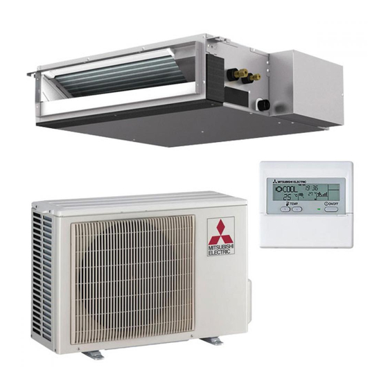
- Page 1 Air-Conditioners SUZ- KA25, KA35, KA50, KA60, KA71VA INSTALLATION MANUAL FOR INSTALLER English For safe and correct use, read this manual and the indoor unit installation manual thoroughly before installing the air-conditioner unit.
-
Page 2: Table Of Contents
Contents 1. The following should always be observed for safety ........ 2 2. Selecting the installation location ............. 2 3. Installation diagram .................. 3 4. Drain piping for outdoor unit ..............3 5. Refrigerant piping work ................4 6. Electrical work ..................6 7. -
Page 3: Installation Diagram
3. Installation diagram I SUZ-KA25/KA35VA 3.1. Outdoor unit (Fig. 3-1) Ventilation and service space I SUZ-KA25/KA35VA A 100 mm or more B 350 mm or more C Basically open 100 mm or more without any obstruction in front and on both sides of the unit. D 200 mm or more (Open two sides of left, right, or rear side.) I SUZ-KA50/KA60/KA71VA A 100 mm or more... -
Page 4: Refrigerant Piping Work
5. Refrigerant piping work 5.1. Refrigerant pipe (Fig. 5-1) s Check that the difference between the heights of the indoor and outdoor units, the length of refrigerant pipe, and the number of bends in the pipe are within the limits shown below. A Indoor unit B Outdoor unit Models... - Page 5 5. Refrigerant piping work 5.2.5. Check (Fig. 5-7) • Compare the flared work with a figure in right side hand. • If flare is noted to be defective, cut off the flared section and do flaring work again. a Smooth all around f Scratch on flared plane b Inside is shining without any scratches g Cracked...
-
Page 6: Electrical Work
6. Electrical work 6.1. Outdoor unit (Fig. 6-1, Fig. 6-2, Fig. 6-3, Fig. 6-4) 1 Remove the service panel. 2 Wire the cables referring to the Fig. 6-1, Fig. 6-2, Fig. 6-3 and the Fig. 6-4. A Indoor unit B Outdoor unit C Wired main switch/fuse D Grounding For Power supply... -
Page 7: Maintenance
6. Electrical work 6.2. Field electrical wiring Outdoor unit model SUZ-KA25/KA35 SUZ-KA50/KA60/KA71 Outdoor unit power supply ~/N (single), 50 Hz, ~/N (single), 50 Hz, 230 V 230 V Outdoor unit input capacity 10 A 20 A Main switch (Breaker) 2 × Min. 1.5 2 ×... - Page 8 Please be sure to put the contact address/telephone number on this manual before handing it to the customer. HEAD OFFICE: TOKYO BLDG., 2-7-3, MARUNOUCHI, CHIYODA-KU, TOKYO 100-8310, JAPAN Printed in Thailand BG79U686K01...
Need help?
Do you have a question about the Mr.Slim SUZ-KA25 and is the answer not in the manual?
Questions and answers