Table of Contents
Advertisement
Quick Links
Advertisement
Table of Contents

Related Manuals for VIPColor VP2020


Summary of Contents for VIPColor VP2020
- Page 1 VP2020 Printer U s e r G u i d e...
- Page 2 PCL is a trademark of Hewlett-Packard Company VIPColor is a trademark of VIPColor Technologies, U.S.A., Inc All other company and product names may be the registered trademarks or trademarks of their respective owners. VP2020 User Guide 05/2004 WARNING Electrical Shock Hazard Serious shock hazard leading to death or injury may result if you do not take the following precautions: •...
-
Page 3: Table Of Contents
Contents Parts of the Printer 1 Setting up the Printer Choose a location for the printer ........1 Unpack the printer . - Page 4 OPTIONS menu..........47 COUNTRY CONFIG menu .
-
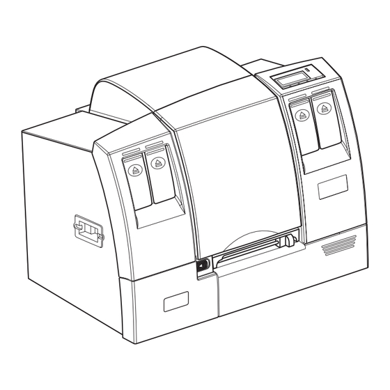
Page 5: Parts Of The Printer
Parts of the Printer The following figures show the locations and names of key printer parts. top cover control panel ink cartridge front access door manual cutter service station access door... - Page 6 USB connector PCMCIA slot Ethernet connector memory expansion bay rear access door Power switch* power socket * Always turn the printer off using the Power button on the control panel, to ensure that the printhead carriage is returned to its proper position at the left side of the printer.
-
Page 7: Setting Up The Printer
C h a p t e r 1 Setting up the Printer To set up the printer, you need to do the following: • Choose a suitable location for setting up the printer. • Unpack the printer. • Connect the power cable. •... -
Page 8: Unpack The Printer
Unpack the printer When unpacking the printer, take care as it is heavy. You should always get help from another person to unpack and lift the printer. 1. Carefully lift the printer out of the box and set it on a level and sturdy surface in the selected location. -
Page 9: Connect The Power Cable
Connect the power cable Make sure the packing material inside NOTE: the printer has been removed and the printer cover is closed. 1. Attach the power cable securely to the printer before plugging the other end into a power outlet. 2. -
Page 10: Install Printheads And Cartridges
Install printheads and cartridges The printer uses four ink cartridges (CMYK – Cyan, Magenta, Yellow and blacK), five printheads, and five printhead cleaners (there are two black printheads). The ink cartridges, printheads and printhead cleaners have to be correctly installed before the printer will function properly. ink cartridge printhead cleaner printhead... -
Page 11: Install Printhead Cleaners
Install printhead cleaners Each new printhead comes with a printhead cleaner.The printhead cleaners protect the printheads when the printer is not in use, and keep the printheads clean for optimum print quality. The printhead cleaners are installed in the service station at the bottom left of the printer, below the printhead carriage. Each printhead cleaner is designed to work with a particular color printhead. -
Page 12: Install Printheads
Install printheads 1. Open the top cover of the printer. The printhead carriage will move to the center of the printer. 2. Remove the packing tape from each of the latches on the carriage. 3. Remove a printhead from its packaging, then remove the protective cap and tape. - Page 13 4. Look at the carriage, which has colored labels showing where the printhead for each color should be installed. Release and flip up the latch for the printhead you are installing. 5. Push the printhead firmly into the carriage. You will not be able to push the printhead NOTE: in place if it is in the wrong slot.
-
Page 14: Load Continuous Media
Load continuous media The following cutaway view shows the path of the media through the printer and important parts inside the printer. media roll loaded in spindle clamp that locks spindle in place lever to release (one on each frame side of the roll) frame that supports media roll... - Page 15 2. Push and hold the green lever to lift up the frame that supports the media roll. Make sure you push the frame up to its highest level so that the pinch rollers (see the figure on page 8) are raised above the platen.
- Page 16 5. Pull the green lock ring and the right side of the spindle off the central core. 6. Insert the spindle into the roll. The free end of the roll should hang off the front. 7. Replace the right side of the spindle and push it against the roll.
- Page 17 8. Place the spindle into the frame. The gear of the spindle should be on the left and the free end of the roll in front. 9. Slip the media loading tool over the free end of the roll. Align the media against the left side of the tool.
- Page 18 11. Feed the loading tool through the opening above the rollers at the back of the printer. 12. Continue feeding the media in until it appears under the pinch rollers. Make sure the media runs under the Top-of-Form sensor (on the left, in front of the pinch rollers).
- Page 19 14. Remove the media loading tool. 15. Make sure the edge of the media is lined up against the red alignment mark on the left. Check that the media has been fed correctly through the printer (steps 11 to 15) as shown below. under the under the pinch rollers Top-of-Form sensor...
- Page 20 16. Move the media width guide against the right alignment edge of the media. arrow ruler To position the media width guide correctly, you Placement of media width guide can make use of the alignment arrow and the green green band •...
-
Page 21: Run The Printhead Alignment Procedure
19. Press the Feed button on the control panel. The printer will feed the media and correctly position it for printing. ONLINE The control panel will show that the printer is now ONLINE Feed Menu Run the printhead alignment procedure The automatic printhead alignment procedure must be performed during installation and whenever you load new printheads in the printer. -
Page 22: Connect The Printer To A Computer
Connect the printer to a computer To connect the printer to a single computer, use the USB connector at the back of the printer. If the computer does not have a USB connector or the operating system NOTE: does not support USB, connect the printer using a CAT5 cross-over cable as described in the next section. -
Page 23: Connect The Printer To A Network
Connect the printer to a network To connect the printer to a network, use the 10BaseT Ethernet connector at the back of the printer. If connecting the printer directly to a single computer, use a CAT5 cross-over cable. 1. Insert the cable into the Ethernet connector at the back of the printer. 2. -
Page 24: Enter Tcp/Ip Parameters
Enter TCP/IP parameters The TCP/IP parameters are entered using the printer’s control panel. On the control panel, press to scroll through the menus; and press to select an option. Connecting to a single computer 1. When giving the printer an IP address, you may have to look at or change the IP setting of your computer, because the first three sets of digits in the IP address of the computer and printer must be the same. - Page 25 Connecting to a network that requires a fixed IP address 1. Set up a fixed IP address (network): a. On the control panel, press the button to enter the main menu. Menu b. Select INTERFACE c. Select TCPIP d. Select MANUAL e.
-
Page 26: Install The Printer Driver
Install the printer driver The printer driver works with Windows 98 and above (for detailed requirements, see page 94). Install the printer driver from the CD-ROM labeled ‘BarTender Label Printing Software, VIPColor Special Edition’. 1. Insert the CD-ROM into the drive. 2. - Page 27 You can also install the BarTender Label Printing Software which lets you design and print labels using various types of image files (including .bmp, .dxf, .img, .jpg, .pcx, .dcx, .png, and .tif). You may also use other Windows applications to design labels and use other types of image files. VIPColor Technologies endeavours to test the driver with multiple NOTE: software applications, but does not guarantee its error-free operation, and...
-
Page 28: Set Up Email Warnings (Optional)
Set up email warnings (optional) If you are using an Ethernet connection, the printer can be set up to send out email messages to selected recipients when problems are encountered, so that action can be taken. • An email account must be set up for the printer. You will need to know the account name and password, as well as the POP3 and SMTP server address. -
Page 29: Printing On Different Types Of Media
C h a p t e r 2 Printing on Different Types of Media The printer supports a variety of label types and shapes, from die-cut labels to continuous media. For best operation, it is strongly recommended that you use the specially coated media types listed below. -
Page 30: Load A New Media Roll
Your label supplier can tell you which profile is best for your media. Load a new media roll The following cutaway view shows the path of the media through the printer and important parts inside the printer. media roll loaded in spindle clamp that locks spindle in place... - Page 31 1. Open the printer’s top cover. 2. Push and hold the green lever to lift up the frame that supports the media roll. Make sure you push the frame up to its highest level so that the pinch rollers (see the figure on page 24) are raised above the platen.
- Page 32 4. Remove the spindle from the frame, by lifting it slightly upwards and towards yourself. If you are replacing the media roll, gently pull the free end of the roll out of the printer. 5. Pull the green lock ring and the right side of the spindle off the central core.
- Page 33 7. Replace the right side of the spindle and push it against the roll. If you can’t fit it back over the central core, rotate it slightly so that the notches on the two parts line up properly. Then replace the lock ring.
- Page 34 10. Reach inside the printer and push the green media width guide to the right. 11. Feed the loading tool through the opening above the rollers at the back of the printer. 12. Continue feeding the media in until it appears under the pinch rollers.
- Page 35 13. Finally, feed the media through the cutter. 14. Remove the media loading tool. 15. Make sure the edge of the media is lined up against the red alignment mark on the left. R I N T I N G O N I F F E R E N T Y P E S O F E D I A...
- Page 36 Check that the media has been fed correctly through the printer (steps 11 to 15) as shown below. under the under the pinch rollers Top-of-Form sensor against the red alignment mark through the manual cutter 16. Move the media width guide against the right alignment edge of the media.
- Page 37 To position the media width guide correctly, you Placement of media width guide can make use of the alignment arrow and the green green band • Pre-cut labels bands on the ruler. on ruler The diagram on the left illustrates the correct alignment placement for 4”...
-
Page 38: Set The Media Selector
Set the media selector Check that the media selector is set according to the type of media (tag media or labels) loaded in the printer. 1. Flip open the access door at the front of the printer. 2. Push the media selector up for tag media and down for labels. -
Page 39: Barcode Safe Mode
Barcode safe mode The VP2020 has a special which ensures that the printing of Barcode safe mode barcodes is optimized for the best readability. In this mode, the printer adjusts the way that it prints to produce better optimized barcodes. You may notice a reduction in the print speed when printing barcodes. - Page 40 R I N T I N G O N I F F E R E N T Y P E S O F E D I A...
-
Page 41: Printer Control Panel
C h a p t e r 3 Printer Control Panel The printer functions and settings that can be changed from the printer’s control panel include setting up optional accessories, changing consumables, and other service routines. Some of the printer settings may also be available in the printer driver. - Page 42 Button/Light Description Error light Turns on when errors occur. Power light Turns on when the power is turned on. Flashes when data is being received. The leftmost button is the Esc button which is used to cancel the current function, for example, to cancel the current print job. When a function can be canceled, ‘Esc’...
-
Page 43: Selecting Printer Options
Selecting printer options When the printer is , press the Menu button to take the printer offline and ONLINE enter the main menu of options. To select an option, use the button to highlight the option and then press PRINTHEAD MAINTENANCE CLEAN PRINTHEADS PRINT STATUS LABEL Press this... -
Page 44: Main Menu
Main menu The printer options are organized in a hierarchy of menus. The options on the main menu are as follows: Option Description PRINTHEAD Menu of options that let you replace and check the printheads. MAINTENANCE CLEAN PRINTHEADS Starts a cleaning cycle of the printheads. PRINT STATUS LABEL Prints a status label which is useful for troubleshooting. -
Page 45: Summary Of Submenus And Options
Selecting any of the options on the main menu displays a submenu (except for options). The submenus and CLEAN PRINTHEADS PRINT STATUS LABEL options are described in the following pages. Summary of submenus and options The following charts show the hierarchy of menus and submenus. R I N T E R O N T R O L A N E L... - Page 46 * For information about passwords, see page 50. R I N T E R O N T R O L A N E L...
-
Page 47: Submenus And Options
Submenus and options PRINTHEAD MAINTENANCE menu This shows a menu of options that let you replace and check the printheads Option Description INSTALL/REPLACE Displays instructions for changing printheads. PRINTHEAD Runs the automatic alignment ALIGNMENT procedure for new printheads. Load a roll of 6”... -
Page 48: Test Menu
TEST menu This shows a menu of test labels that you can print. Option Description TEST PRINTS TEST PRINT A Select an option to print the TEST PRINT B predefined test labels. Load a roll of 6” continuous media before running this procedure. - Page 49 The following is a sample status label: VIPColor VP2020 Diagnostic Page Model ID: VIPColor VP2020 Label Printer Main board firmware version: 3.0 built at April 02, 2004 11:38:41 -ROP Mech board firmware version: 07000396 Carriage board firmware version: 0010004A Printer serial number: SG2022302H...
-
Page 50: Advanced Menu
ADVANCED menu This shows a menu of service options. Option Description FACTORY DEFAULT Changes all settings back to the factory defaults and clears the printer’s Flash and DRAM memory areas. READ METRICS [COLOR] PRINTHEAD Displays list of items for which [COLOR] CARTRIDGE usage data is available. - Page 51 Option Description FIRST LABEL MODE Stops the label from going to the cutter position after a print job, thereby preventing unwanted paper movement back and forth in between print jobs. When this option is off, the printer will position the paper for cutting if the next print job does not arrive within a predefined period.
-
Page 52: Maintenance Menu
MAINTENANCE menu This shows a menu of maintenance options. Option Option Description CHANGE SERVICE Lets you change the printhead STATION cleaners. PRINTHEAD AUTO ALIGNMENT Runs the automatic alignment ALIGNMENT procedure for new printheads. Load a roll of 6” continuous media before starting this procedure. -
Page 53: Options Menu
OPTIONS menu This shows the settings for optional accessories such as the automatic cutter. Option Description AUTO CUTTER Specifies if the automatic cutter is installed. SINGLE DISPENSE Specifies if single dispense mode is installed. MANUAL CUTTER Specifies if the manual cutter is installed. -
Page 54: Country Config Menu
COUNTRY CONFIG menu This menu lets you select the display language and unit of measure. Option Description LANGUAGE ENGLISH* Lets you select the language SELECTED JAPANESE display for the control panel. UNITS OF MEASURE INCHES* Lets you select the unit of measure used by the printer. -
Page 55: Interface Menu
INTERFACE menu This menu shows the printer interface settings. Option Option Description ETHERNET DEFAULT TO CABLE Specifies whether to use the cable or wireless network connection. TCPIP MANUAL Select MANUAL to enter settings IP ADDR manually, or select DHCP or BOOTP. SUBNET MASK GATEWAY DHCP... -
Page 56: Password Menu
PASSWORD menu This menu lets you change the level 1 and 2 passwords for the control panel. Description LEVEL 1 PASSWORD Lets you set the level 1 password. LEVEL 2 PASSWORD Lets you set the level 2 password. The two levels of passwords control access to different types of options. A level 1 password protects options that operators may need to access, while a level 2 password protects options not normally used in daily operations. -
Page 57: Printer Internal Web Pages
C h a p t e r 4 Printer Internal Web Pages If your printer is on a network, you will be able to check its status and settings from a remote computer. This information is provided in the printer’s internal web pages, which you can log on to using a standard web browser. - Page 58 2. In the dialog box that appears, enter ‘administrator’ for the User Name and ‘vipcolor’ for the Password. The Password Setup page will appear. 3. Enter a new administrator’s password in the VIP Web Password field and click Apply. The home page will appear.
-
Page 59: Home Page
Home page Once your user name and password are accepted, the printer’s home page shows the current printer status, and provides links to other web pages in the left navigation bar. Option Description Password Displayed only if you log on as ‘administrator’. It allows you to change the web passwords, the level 1 and 2 passwords for accessing the printer’s control panel, and the printer name. -
Page 60: Password
Option Description Set Up Email Warnings Allows you to specify who to send email messages to when problems occur. Country Configuration Allows you to select the language and unit of measure. Home Returns to the printer’s start page. VIPColor Website Links to the VIPColor Website. -
Page 61: Current Active Stock
Maximum of 8 alphanumeric characters. Printer name Maximum of 15 alphanumeric characters. * The VIP Web Password is used to access the printer’s internal web pages. Current Active Stock This option lets you verify the settings for the media in the printer before starting a print run. -
Page 62: Metrics
Metrics This option shows the usage data for the ink cartridges, printheads, printhead cleaners, and mechanism. To view the data, 1. Select Metrics from the left navigation bar, then select an item. 2. Select the color, if applicable. For example, select Ink Cartridges, then select Cyan to see the metrics for the cyan ink cartridge, as shown in the following screen. - Page 63 R I N T E R N T E R N A L A G E S...
-
Page 64: Option Install
Option Install This option shows which of the optional accessories have been installed in the printer, and the amount of available memory. From this page, you can edit the wireless Ethernet settings and check the SIMM jumper settings. R I N T E R N T E R N A L A G E S... - Page 65 Specify wireless Ethernet settings When you install a wireless Ethernet card, be sure to enter the correct settings for the card. On the Option Install page, click the ‘Not installed’ hyperlink in the Wireless Ethernet field. This displays the following page: Enter the settings and click Apply to save.
- Page 66 Check SIMM jumper settings On the Option Install page, click the hyperlink in the SIMM Size field to check the jumper settings. R I N T E R N T E R N A L A G E S...
-
Page 67: Test Functions
Test Functions This option allows you to print test labels and to test a number of printer functions. Test Description Feed Feeds media through the printer. Barcode label Print test labels. Load 6” media before running these Graphic label tests. Check print head Check the printhead nozzles and display the test results. -
Page 68: Available Fonts
Available Fonts This option shows the fonts that are currently loaded into the memory. R I N T E R N T E R N A L A G E S... -
Page 69: Set Up Email Warnings
Set Up Email Warnings This option allows you to set up the printer to send email messages to selected recipients when any problems occur. You can specify up to three recipients. You can also add more details to the standard message sent by the printer. To do so, enter the text in the Warning Add On field. - Page 70 Set up email properties Fill in the fields and click Apply to save the settings. R I N T E R N T E R N A L A G E S...
-
Page 71: Country Configuration
Country Configuration This option lets you select the language and the unit of measure. Select from the drop-down lists and click Apply to save. R I N T E R N T E R N A L A G E S... - Page 72 R I N T E R N T E R N A L A G E S...
-
Page 73: Changing Cartridges And Printheads
C h a p t e r 5 Changing Cartridges and Printheads The printer displays messages to warn you before an ink cartridge, printhead, or printhead cleaner needs to be replaced. While the printer will still be able to print, it is best to get replacements ready when you see these messages. Handle all these consumables with care as ink spills may cause damage NOTE: to the electronics of the printer and may stain. -
Page 74: Replace An Ink Cartridge
Replace an ink cartridge Remove an ink cartridge 1. Push the ink cartridge in and slightly upwards. It will pop free, allowing you to remove it from the slot. Install an ink cartridge 1. Remove the ink cartridge from its packaging. 2. -
Page 75: Replace A Printhead
Replace a printhead Each new printhead comes with a printhead cleaner. Always replace the printhead cleaner together with the printhead. If NOTE: the printhead cleaner is not replaced, it can affect the print quality and reduce the life of the printhead. Remove a printhead 1. - Page 76 The printhead carriage will move to the center of the printer. 3. For easier access, you may like to lift up the frame that supports the media roll. Push and hold green lever the green lever on the frame to lift it. 4.
- Page 77 5. Lift the printhead out of the carriage by pulling the handle on its top. Install a new printhead 1. Remove the new printhead from its packaging, then remove the protective tape and cap. Take care not to touch the nozzles of the NOTE: printhead.
- Page 78 3. Flip the latch down over the printhead and secure it by pressing down. 4. Close the printer’s top cover. This returns the carriage to the left side of the printer. 5. Every time you replace a printhead, always do the following as well: –...
-
Page 79: Replace A Printhead Cleaner
Replace a printhead cleaner Remove a printhead cleaner 1. Slide the lock to the right to release the access door. The service station will move forward automatically. 2. Push and hold the tab up to release the printhead cleaner and pull it out of the slot. H A N G I N G A R T R I D G E S A N D R I N T H E A D S... - Page 80 Install a printhead cleaner 1. Insert the new printhead cleaner into the slot and push it in firmly by its top. You should hear a click as it snaps into place. 2. Close the access door and slide the lock to the left to lock it.
-
Page 81: Troubleshooting
C h a p t e r 6 Troubleshooting This chapter provides solutions to some basic problems. Error messages on control panel The printer normally detects problems and displays messages for preventive actions or remedies. You can check the control panel for these messages. You can also set up the printer to send these messages via email to selected recipients. - Page 82 The following table shows some other messages you may see on the display panel, as well as the action to take. Message Possible Reason Remedy Media out • Wrong media sensor selected Check that the media is loaded correctly. • Media is not fed under the sensor •...
-
Page 83: If The Carriage Is Unable To Move
If the carriage is unable to move If the media is crushed under the carriage and it is unable to move, follow these instructions to clear the jam. 1. Make sure you turn the printer off by pressing the Power button on the control panel. - Page 84 5. Unscrew and remove the rear access door of the printer. 6. Reach beneath the rear media guide and push the green lever to the left. The rear media guide will drop down. 7. Remove the jammed media. green lever rear media guide 8.
- Page 85 10. When you have cleared all the media from the printer, place the arms of the main media guide into the guide rails on both sides, and slide it into the printer. 11. Push the rear media guide up till it clicks into rail place.
-
Page 86: Print Quality Problems
Print quality problems This section describes the print quality problems you may see and the remedies. • Horizontal gaps, overlapping swaths, or slight changes in color between swaths can be seen in the printouts. horizontal gaps or overlaps occurring at regular intervals (0.85”... -
Page 87: Adjustments And Calibrations
• Straight lines do not print properly but seem to shift, like in the following example. Run the automatic printhead alignment procedure described below. If the problem persists, perform manual alignment as described on page 82. Adjustments and calibrations Printhead alignment Automatic alignment The automatic printhead alignment procedure must be performed whenever you load new printheads in the printer. - Page 88 Manual alignment Always run the auto printhead alignment before attempting manual alignment. If you are still not satisfied with the print results after the auto alignment procedure, then perform manual alignment as described below. Manual alignment uses a series of four test patterns or plots. You check the plots and make adjustments where necessary.
- Page 89 In the printout, the four plots will look similar to the following: Each plot consists of a number of colored bands. The squares in each color band are numbered -3 to 3 from left to right. In each color band, the lightest square should be at zero.
- Page 90 4. When you have finished making adjustments, select to print PRINT PATTERN 2 the following test pattern and check the result of the alignment. All the lines should print correctly. R O U B L E S H O O T I N G...
-
Page 91: Media Calibration
Media calibration If you are using media for which a color profile is available, the printer is automatically calibrated to produce the best output on that media and you can now start printing. However, you will need to run the media calibration procedure when: •... - Page 92 Automatic calibration Automatic calibration is normally only used to set up the printer after maintenance. 1. Load the media. • To set up the printer after maintenance, load a roll of 6” Demandjet 200U continuous media. • To set up the printer for one specific media type, load that media type. 2.
- Page 93 5. Rotate the test strip clockwise and place it on the platen, in front of the paper sensor and against the red alignment mark. Make sure that it lies flat; if necessary, feed the front edge of the strip through the cutter. pinch rollers paper sensor alignment mark...
-
Page 94: Printer Maintenance
Printer maintenance It recommended that you clean the printer after every 20 rolls of media. • Clean ink and dust from the platen and rollers using a soft cloth. • If adhesive is present, use a soft cloth lightly moistened with isopropyl alcohol to remove it. -
Page 95: Optional Accessories
C h a p t e r 7 Optional Accessories The wireless LAN card is an optional accessory you can install in the VP2020 printer. The PCMCIA slot is at the back of the printer, between the USB and network connectors. Follow the instructions provided with the card to install it. -
Page 96: Expanding Sdram
Expanding SDRAM 1. Turn the printer off and remove the power cable. 2. Unscrew and remove the rear access panel on the left. The top slot is for the DIMM and the bottom slot for the SIMM. 3. To remove the DIMM, press the socket clips outwards till the DIMM slides out of the socket. -
Page 97: Expanding Flash Memory
Expanding flash memory 1. Turn the printer off and remove the power cable. 2. Unscrew and remove the rear access panel on the left. The top slot is for the DIMM and the bottom slot of the SIMM. 3. Remove the SIMM from its packaging. 4. - Page 98 P T I O N A L C C E S S O R I E S...
-
Page 99: Printer Specifications
C h a p t e r 8 Printer Specifications Print technology Based upon HP inkjet technology CMYK scanning heads Printing language: HP PCL XL Printing modes 300 x 600 dpi or 600 x 600 dpi and barcode safe selectable Throughput Up to 50, 6”... - Page 100 Print media Media type Die cut labels Tag media Black mark media Label roll sizes Internal core cardboard: 3” (76 mm) diameter Maximum external roll size: 8” (203 mm) diameter Maximum width 6” Media thickness 7 mil to 11 mil Media loading Label roll loaded from the front of the printer Label roll protected from dust and pollutants...
-
Page 101: Media Dimensions And Printable Area
Media dimensions and printable area The following diagram shows the dimensions of the media types that can be used in the printer. Face of die-cut label Face of perforated tag media Rear of tag media (for transmissive sensor) (for transmissive sensor) (for reflective sensor) Dimension Minimum... - Page 102 R I N T E R P E C I F I C A T I O N S...
- Page 103 Index error messages on control panel 76 Esc button 36 accessing printer web pages 51 Ethernet connector 17 adhesive, removing 88 expanding flash memory 91 ADVANCED menu 44 expanding SDRAM 90 aligning printheads 81 auto calibration 85 auto printhead alignment 81 Feed button 36 flash memory expansion 91 front view of printer v...
- Page 104 media calibration 85 PRINTHEAD MAINTENANCE menu 41 media jam 77 printheads 4 media path 24 aligning 82 media roll dimensions 95 installing 71 media selector 32 replacing 69 media types 23 printing barcodes 33 memory expansion bay vi problems, solving 75 memory upgrades 89 protecting the printheads 3 Menu button 36...
- Page 105 view inside the printer 24 warning via email 22 warnings via email 63 web page access to printer functions 51 web page password 54 wireless Ethernet card 89 wireless Ethernet settings 59...
- Page 106 VIPColor Technologies Pte Ltd...
Need help?
Do you have a question about the VP2020 and is the answer not in the manual?
Questions and answers