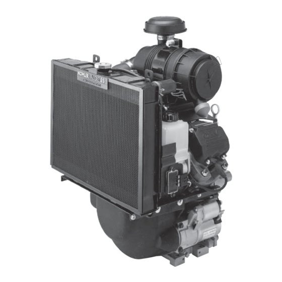
Kohler AEGIS LH630 Service Manual
Liquid-cooled horizontal crankshaft
Hide thumbs
Also See for AEGIS LH630:
- Owner's manual (21 pages) ,
- Service manual (177 pages) ,
- Service manual (73 pages)
Table of Contents
Advertisement
Quick Links
Download this manual
See also:
Owner's Manual
Advertisement
Chapters
Table of Contents
Troubleshooting

Subscribe to Our Youtube Channel
Related Manuals for Kohler AEGIS LH630


Summary of Contents for Kohler AEGIS LH630
- Page 1 ERVICE ANUAL AEGIS LH630, LH685, LH750, LH760 ™ IQUID OOLED ORIZONTAL RANKSHAFT Not For Resale www.SmallEngineDiscount.com...
-
Page 2: Not For Resale
Contents Section 1. Safety and General Information ................Section 2. Special Tools ......................Section 3. Troubleshooting ..................... Section 4. Air Cleaner System ....................Section 5. Fuel System and Governor ..................Section 5B. Electronic Fuel Injection (EFI) Fuel System ............Section 6. Lubrication System ....................Section 7. - Page 3 Section 1 Safety and General Information LH630, LH685, LH750, LH760 Section 1 Safety and General Information Safety Precautions To ensure safe operations please read the following statements and understand their meaning. Also refer to your equipment manufacturer's manual for other important safety information. This manual contains safety precautions which are explained below.
-
Page 4: Section 1 Safety And General Information
Section 1 Safety and General Information WARNING WARNING WARNING Explosive Gas can cause fires and Explosive Fuel can cause fires and Carbon Monoxide can cause severe acid burns. severe burns. severe nausea, fainting or death. Charge battery only in a well Stop engine before filling fuel tank. - Page 5 Section 1 Safety and General Information Engine Identification Numbers When ordering parts, or in any communication involving an engine, always give the Model, Specification, and Serial Numbers, including letter suffixes if there are any. The engine identification numbers appear on a decal, or decals, affixed to the engine.
- Page 6 Section 1 Safety and General Information Oil Recommendations Refer to Section 6 - “Lubrication System” for detailed procedures on checking the oil, changing the oil and Using the proper type and weight of oil in the changing the oil filter. crankcase is extremely important.
- Page 7 Gasohol (up to 10% ethyl alcohol, 90% unleaded gasoline with a pump sticker octane rating of 87 or gasoline by volume) is approved as a fuel for Kohler higher. In countries using the Research method, it engines. Other gasoline/alcohol blends are not should be 90 octane minimum.
- Page 8 Section 1 Safety and General Information Storage 4. The fuel system must be completely emptied, or the gasoline must be treated with a stabilizer to If the engine will be out of service for two months or prevent deterioration. If you choose to use a more, use the following storage procedure: stabilizer, follow the manufacturer’s recommendations, and add the correct amount...
- Page 9 Section 1 Safety and General Information 440.00 Oil Filter Side (17.323) (.906) Rain Cap Removal Optional Oil Fill Fuel Pump 673.70 (26.524) Overall 622.54 (24.509) Overall without Rain Cap 152.08 (5.987) Drain 38.00 2X 184.20 (1.496) (7.252) 143.25 175.41 127.90 C L Mounting Hole (5.640) (6.906)
- Page 10 Section 1 Safety and General Information General Specifications Power (@ 3600 RPM, corrected to SAE J1995) LH630 ..............Maximum ..... 16.4 kW (22 HP) Recommended ..13.9 kW (18.7 HP) LH685 ..............Maximum ..... 18.6 kW (25 HP) Recommended ..15.9 kW (21.3 HP) LH750 ..............Maximum .....
- Page 11 Section 1 Safety and General Information Camshaft cont. Bore I.D. New ....................20.000/20.025 mm (0.7874/0.7884 in.) Max. Wear Limit ................20.038 mm (0.7889 in.) Camshaft Bearing Surface O.D. New ....................19.962/19.975 mm (0.7859/0.7864 in.) Max. Wear Limit ................19.959 mm (0.7858 in.) Carburetor and Intake Manifold Intake Manifold Fastener Torque (torque in 2 increments) ....
- Page 12 Section 1 Safety and General Information Crankshaft cont. Main Bearing Journals O.D. - New ..................40.913/40.935 mm (1.6107/1.6116 in.) O.D. - Max. Wear Limit ..............40.84 mm (1.608 in.) Max. Taper ..................0.022 mm (0.0009 in.) Max. Out-of-Round ................ 0.025 mm (0.0010 in.) Crankshaft to Sleeve Bearing (crankcase) Running Clearance - New ..............
- Page 13 Section 1 Safety and General Information Fan/Flywheel Rear Fan Shaft to Mounting Bracket Nut Torque ........15.8 N·m (140 in. lb.) Front Fan Assembly to Fan Shaft Nut Toque ........15.8 N·m (140 in. lb.) Fan/Pulley/Hub Assembly Fastener Torque .......... 6.8 N·m (60 in. lb.) Flywheel Retaining Screw Torque ............
- Page 14 Section 1 Safety and General Information Piston, Piston Rings, and Piston Pin Piston-to-Piston Pin ................0.006/0.018 mm (0.0002/0.0007 in.) Piston Pin Bore I.D. New ....................17.006/17.013 mm (0.6695/0.6698 in.) Max. Wear Limit ................17.025 mm (0.6703 in.) Piston Pin O.D. New ....................
- Page 15 Section 1 Safety and General Information Piston, Piston Rings, and Piston Pin cont. Piston Thrust Face-to-Cylinder Bore² Running Clearance LH630 .................... 0.014/0.057 mm (0.0005/0.0022 in.) LH685 .................... 0.019/0.062 mm (0.0007/0.0024 in.) LH750, LH760 ................0.015/0.058 mm (0.005/0.0022 in.) Speed Control Speed Control Bracket Assembly Fastener Torque .......
- Page 16 Section 1 Safety and General Information General Torque Values Metric Fastener Torque Recommendations for Standard Applications Tightening Torque: N·m (in. lb.) + or - 20% Property Class Noncritical Fasteners 12.9 10.9 Into Aluminum Size 1.2 (11) 1.7 (15) 2.9 (26) 4.1 (36) 5.0 (44) 2.0 (18)
- Page 17 Section 1 Safety and General Information English Fastener Torque Recommendations for Standard Applications Tightening Torque: N·m (in. lb.) + or - 20% Bolts, Screws, Nuts and Fasteners Grade 2 or 5 Assembled Into Cast Iron or Steel Fasteners Into Aluminum Grade 2 Grade 5 Grade 8...
-
Page 18: Special Tools
By using tools designed for the job, you can service engines easier, faster, and safer! In addition, you’ll increase your service capabilities and customer satisfaction by decreasing engine downtime. Kohler special tools are handled by SPX Corp., a division of Owatonna Tool Corp. (OTC). The tools are easy to purchase by contacting SPX/OTC by phone, fax, or mail. -
Page 19: Section 2 Special Tools
I.D. to slip on the capscrew and an O.D. of Flywheel Holding Tool approximately 1". Kohler Part No. 12 468 05-S can be Flywheel removal and reinstallation becomes a ‘‘snap’’ using a handy holding tool you can make out of a used if you don't have the right size on hand. - Page 20 Section 3 LH630, LH685, LH750, LH760 Troubleshooting Section 3 Troubleshooting Troubleshooting Guide 5. Faulty choke or throttle controls. 6. Faulty spark plugs. When troubles occur, be sure to check the simple 7. Low compression. causes which, at first, may seem too obvious to be 8.
-
Page 21: Section 3 Troubleshooting
Section 3 Troubleshooting Engine Overheats (cont.) • Check for buildup of dirt and debris on the radiator, crankcase, cooling system components, and other 6. Lean fuel mixture. 7. Fan belt failed/off. external surfaces. Dirt or debris on these areas 8. Cooling fan broken. are causes of higher operating temperatures and overheating. - Page 22 Section 3 Troubleshooting Cleaning the Engine 3. Open the clamp and note the water level in the tube. After inspecting the external condition of the engine, clean the engine thoroughly before disassembling it. The level in the engine side should be a minimum Also clean individual components as the engine is of 10.2 cm (4 in.) above the level in the open disassembled.
- Page 23 Section 3 Troubleshooting Leakdown Test Instructions If the engine is mounted in a piece of equipment, 1. Run engine 3-5 minutes to warm it up. you may be able to hold it by clamping or wedging a driven component. Just be certain that the 2.
- Page 24 Section 4 Air Cleaner System Air Cleaners General These engines are equipped with Kohler's heavy-duty, cyclonic air cleaner system. See Figure 4-1. The air cleaner includes a high-density, pleated paper main element (see Figure 4-2), and inner safety element (see Figure 4-3).
- Page 25 Replace any damaged or questionable components. 5. If it is being replaced, install the new inner element, Kohler Part No. 25 083 04-S, followed by the canister outer element; Kohler Part No. 25 083 01-S. Slide each fully into place in the housing.
- Page 26 Gasohol (up to 10% ethyl alcohol, 90% unleaded filter and fuel lines by the fuel pump. On engines not gasoline by volume) is approved as a fuel for Kohler equipped with a fuel pump, the fuel tank outlet is engines. Other gasoline/alcohol blends are not located above the carburetor inlet, allowing gravity to approved.
-
Page 27: Section 5 Fuel System And Governor
Periodically inspect the filter and replace when dirty start, it is possible that the problem is in the fuel with a genuine Kohler filter. system. To find out if the fuel system is causing the problem, perform the following tests. - Page 28 Section 5 Fuel System and Governor Mechanical Fuel Pump 3. Remove the vacuum line that connects the pump The mechanical fuel pump is built into the #2 valve to the crankcase. cover. The actuating arm of the pump extends down inside the cover and contacts one of the rocker arms.
- Page 29 Section 5 Fuel System and Governor Fuel Shut-Off Solenoid Most carburetors are equipped with a fuel shut-off solenoid. The solenoid has a spring loaded pin that retracts when 12 volts is applied to the lead. When power ceases, the spring loaded pin extends and blocks the main jet.
- Page 30 Section 5 Fuel System and Governor Adjusting Low Idle Speed (RPM) Setting 1. Start the engine and run at half throttle for 5 to 10 minutes to warm up. The engine must be warm before making final low idle speed (RPM) adjustment.
- Page 31 Section 5 Fuel System and Governor Troubleshooting – Carburetor Related Causes Condition Possible Cause/Probable Remedy 1. Engine starts hard, runs roughly or 1a. Low idle fuel mixture/speed improperly adjusted. Adjust the low idle stalls at idle speed. speed screw b. Low idle fuel mixture circuit blocked/restricted. Clean carburetor as required.
- Page 32 Section 5 Fuel System and Governor Disassembly • The choke plate is spring loaded. Check to make sure it moves freely on the shaft. Disassemble the carburetor using the following steps. See Figure 5-6. Always use new gaskets when servicing or reinstalling carburetors.
- Page 33 Section 5 Fuel System and Governor NOTE: The fuel inlet needle tip is spring loaded. Make sure float assembly rests against the fuel inlet needle without depressing the tip. 6. The correct float height adjustment is 22 mm (0.86 in.) measured from the float bottom to the air horn casting.
- Page 34 Section 5 Fuel System and Governor 1. Carburetor Upper Body (Choke) 2. Self-Relieving Choke 3. Body Gasket (Formed Rubber) 4. Slow Speed Jet 5. Inlet Needle Valve 6. Clip 7. Float Pin 8. Float Assembly (Kit) 9. Carburetor Lower Body (Throttle) 10.
- Page 35 Section 5 Fuel System and Governor Carburetor Service/Repair Kits Solenoid Kit Contains: Description Qty. Always refer to the Parts Manual for the engine being serviced to ensure the correct repair kits and Solenoid Screw replacement parts are ordered. O-Ring O-Ring Carburetor Repair Kit Contains: O-Ring Solenoid Assembly...
- Page 36 Section 5 Fuel System and Governor • As the flyweights move outward, they cause the Reassembly Procedure regulating pin to move outward. Reassemble the carburetor using the following steps. See Figure 5-6. • The regulating pin contacts the tab on the cross shaft causing the shaft to rotate.
- Page 37 Section 5 Fuel System and Governor 1. Governor Lever Hex. Nut 2. Governor Cross Shaft 3. Governor Lever 4. Throttle Lever Linkage 5. Choke Linkage 6. Choke Actuating Lever 7. Governor Spring 8. Speed Control Bracket 9. Governor Lever (Holes for Sensitivity Adjustment) Figure 5-8.
- Page 38 Section 5 Fuel System and Governor Left Side Pull Choke Control Lever #1 Throttle Choke Linkage Control Kill Switch Choke Control Cable Lever #2 Throttle Control Cable Z Bend Throttle Control Cable Kill Switch Adjusting Screw Choke Control Cable Dual Control High Speed Lever Stop Screw High Speed Control Lever High Speed...
-
Page 39: Table Of Contents
Section 5B EFI Fuel System LH760 Section 5B Electronic Fuel Injection (EFI) Fuel System Contents Page(s) Description Initial Starting/Priming Procedure ......................5B.2 Fuel Recommendations ......................... 5B.2 EFI Fuel System Components ....................... 5B.3 Operation ............................... 5B.3 Important Service Notes ......................... 5B.4 Electrical Components Electronic Control Unit (ECU) ...................... -
Page 40: Description
Gasoline/Alcohol blends button on the tester relief valve. Gasohol (up to 10% ethyl alcohol, 90% unleaded gasoline by volume) is approved as a fuel for Kohler EFI Initial Starting/Priming Procedure engines. Other gasoline/alcohol blends are not Important: The EFI fuel system must be purged of all air approved. -
Page 41: Efi Fuel System Components
Section 5B EFI Fuel System EFI Fuel System Components The ECU controls the amount of fuel injected and the ignition timing by monitoring the primary sensor signals for engine temperature, speed (RPM), and throttle General position (load). These primary signals are compared to The Electronic Fuel Injection (EFI) system is a preprogrammed “maps”... -
Page 42: Important Service Notes
MIL. An optional • Do not charge battery with key switch ‘‘on.’’ computer software diagnostic program is also available, order Kohler Part No. 25 761 23-S. • Always disconnect negative (-) battery cable lead before charging battery, and also unplug harness from ECU before performing any welding on equipment. -
Page 43: Engine Speed Sensor
Section 5B EFI Fuel System The ECU requires a minimum of 7.0 volts to operate. General The adaptive memory in the ECU is operational the The engine speed sensor is essential to engine moment the battery cables are connected, however the operation;... - Page 44 Section 5B EFI Fuel System Dual Aligning Rails Corresponds To #9 In Main Corresponds Connector. #10 In Main Connector. Test Terminals Figure 5B-3. Speed Sensor Connector. 7. a. If the resistance is incorrect, remove the screw securing the sensor to the mounting bracket and replace the sensor.
- Page 45 Section 5B EFI Fuel System Mounted on the throttle body/intake manifold and Throttle Between Resistance operated directly off the end of the throttle shaft, the Position Continuity Terminals Value (Ω) TPS works like a rheostat, varying the voltage signal to 2 &...
-
Page 46: Engine (Coolant) Temperature Sensor
If the procedure was unsuccessful see Steps a. and b. No. KO3217-9). See Figure 5B-6. If using the following. PC-based diagnostic tool and software (Kohler Part No. 25 761 23-S), go to “Special Tests” and a. If during this procedure, the “MIL” goes back into follow the prompts to complete. -
Page 47: Oxygen Sensor
Section 5B EFI Fuel System General Oxygen Sensor The engine (coolant) temperature sensor (Figure 5B-7) is used by the system to help determine fuel requirements for starting (a cold engine needs more fuel than one at or near operating temperature). Mounted in the throttle body/intake manifold, it has a temperature- sensitive resistor that extends into the coolant flow. - Page 48 Section 5B EFI Fuel System The oxygen sensor can function only after being heated If voltage momentarily increases and then again by exhaust temperatures to a minimum of 375°C declines, without cycling, engine may be (709°F). A cold oxygen sensor will require running lean due to incorrect TPS initialization.
-
Page 49: Electrical Relay
Section 5B EFI Fuel System b. If the resistance is less than 1.0 MΩ Ω Ω Ω Ω , the 4. Reconnect the lead to wiring harness connector. sensor is bad, replace it. Make sure it can not contact hot surfaces, moving parts, etc. -
Page 50: Fuel Injectors
Section 5B EFI Fuel System 5. Connect an ohmmeter (Rx1 scale) between the Terminal #87 - Terminal #85 - #85 and #86 terminals in the relay. There should Feed To Ignition Ignition Switch Coils, Fuel be continuity. Voltage Injectors, and Fuel Pump 6. - Page 51 Section 5B EFI Fuel System Listen Here Figure 5B-15. Checking Injectors. Multi-Orifice Director Plate With 3. Disconnect the electrical connector from an Calibrated Opening injector and listen for a change in idle performance (only running on one cylinder) or a change in injector noise or vibration.
- Page 52 Section 5B EFI Fuel System 2. Make sure all safety switch requirements are met. 1. Engine must be cool. Depressurize fuel system Crank the engine and check for flashing of test through the test valve in fuel rail. light. Repeat test at other connector. 2.
-
Page 53: Ignition System
Section 5B EFI Fuel System 14. Clean any dirt accumulation from the sealing/ mounting area of the faulty injector(s) and disconnect the electrical connector(s). 15. Pull the retaining clip off the top of the injector(s) and remove from manifold. 16. Reverse the appropriate procedures to install the new injector(s) and reassemble the engine. -
Page 54: Spark Plugs
Section 5B EFI Fuel System 4. If the secondary resistance is not within Battery Charging System the specified range, unscrew the spark EFI engines are equipped with either a 15 or 25 amp plug lead nut from the coil secondary charging system to accommodate the combined tower and remove the plug lead. -
Page 55: Fuel Pressure Regulator
If the pump still does not operate, replace it. may be conducted. Fuel Pressure Regulator 1. Connect the black hose of Kohler pressure tester (SPX Part No. KO3217-4) to the test valve in the fuel rail. Route the clear hose into a portable gasoline container or the equipment fuel tank. - Page 56 Section 5B EFI Fuel System Pressure Regulating Pressure Spring Regulating Chamber Diaphragm Valve Seat Valve Fuel Chamber Inlet Port Outlet Port (to fuel rail) Return Port (to tank) Figure 5B-23. External Regulator and Base/Holder. Figure 5B-22. Fuel Pressure Regulator Details. Service Depending on the application, the regulator may be located in the fuel tank along with the fuel pump, or...
-
Page 57: Fuel Filter
Use only Oetiker clamps The fuel rail is a formed tube assembly that feeds fuel (Kohler Part No. 24 237 05-S) on fuel line connections. to the top of the injectors. The tops of the injectors fit into formed cups in the fuel rail. -
Page 58: Throttle Body/Intake Manifold Assembly
Section 5B EFI Fuel System Throttle Body/Intake Manifold Assembly Adjustment Procedure 1. Make sure there are no fault codes present in the ECU memory. 2. Start the engine and allow it to fully warm up and establish closed looped operation (approximately 5-10 min.). - Page 59 Section 5B EFI Fuel System If the governor/throttle components are all intact, but 4. Check how the end of the throttle linkage aligns you think there may be a problem with the adjustment, with the bushing hole in the governor lever. See follow Procedure A to check the setting.
-
Page 60: Troubleshooting
Section 5B EFI Fuel System 3. Insert a nail into the hole in the top of the cross Troubleshooting Guide shaft. Using light pressure, rotate the governor shaft counterclockwise as far as it will turn, then Engine starts hard or fails to start when cold torque the hex. -
Page 61: Electrical System
Section 5B EFI Fuel System Electrical System If a fault code indicates a problem with an electrical component, disconnect the ECU connector and test for The EFI system is a 12 VDC negative ground system, continuity between the component connector terminals designed to operate down to a minimum of 7.0 volts. - Page 62 Section 5B EFI Fuel System Pin # Function Permanent Battery Voltage Switched Battery Voltage TPS Set; “Auto-Learn” Initialization Terminal Throttle Position Sensor (TPS) and Temperature Sensor Ground Not Used Oil Temperature Sensor Input Not Used Throttle Position Sensor (TPS) Input Speed Sensor Input (+) Speed Sensor Ground (-) Not Used...
- Page 63 Not For Resale www.SmallEngineDiscount.com...
-
Page 64: Fuel System
Section 5B EFI Fuel System Fuel System Fault Codes The ECU continuously monitors engine operation WARNING: Fuel System Under Pressure! against preset performance limits. If the operation is The fuel system operates under high pressure. System outside the limits, the ECU activates the MIL and pressure must be relieved through the test valve in the stores a diagnostic code in its fault memory. - Page 65 Section 5B EFI Fuel System Example of Diagnostic Display 1. Diagnostic display initiated through ignition key sequencing. Long Pause Short Pauses Code 32 Long Pause Code 61 Long Pause Light remains on at end of transmission Figure 5B-35. Diagnostic Display. After the problem has been corrected, the fault codes may be cleared as follows.
- Page 66 Section 5B EFI Fuel System Diagnostic Code Summary Blink OBD2 Note Condition or Failure Description Code P-Code Illuminated – No RPM Signal – P0335 Loss of Synchronization P0120 TPS - Signal Implausible P0122 TPS - Open or Short Circuit to Ground P0123 TPS - Short Circuit to Battery P0601...
- Page 67 Section 5B EFI Fuel System Diagnostic Code Summary Code: Source: Throttle Position Sensor (TPS) Explanation: Unrecognizable signal is being sent Code: from sensor (too high, too low, Source: Engine Speed Sensor inconsistent). Explanation: ECU receiving inconsistent tooth Expected Engine count signals from speed sensor. Response: A “limp-home”...
- Page 68 Section 5B EFI Fuel System If the engine is still running rich Code: (laboring, short on power) or lean Source: (popping or misfiring), the fuel mixture Explanation: ECU is unable to recognize or process is suspect, probably incorrect TPS signals from its memory. initialization or low fuel pressure.
- Page 69 Section 5B EFI Fuel System 2. Oxygen Sensor Related 3. Engine Wiring Harness Related a. Sensor connector or wiring problem. a. Difference in voltage between sensed voltage b. Sensor contaminated or damaged. (pin circuit 2) and actual injector voltage c. Exhaust leak. (circuit 45).
- Page 70 Section 5B EFI Fuel System Code: 43 and 44 2. Engine wiring harness related Source: TPS “Auto-Learn” initialization function a. Broken or shorted wire in harness. ECU pin failed, throttle angle out of learning 14 to injector pin 2. ECU pin 28 to fuel pump range.
-
Page 71: Troubleshooting Flow Chart
Section 5B EFI Fuel System Code: Code: Source: MIL (Diagnostic lamp) circuit open, Source: Fuel pump relay circuit open, shorted to ground, or shorted to battery shorted to ground, or shorted to battery. Explanation: Fuel pump, ignition coils, and fuel Explanation: MIL is not functioning because the injectors will not function because the... - Page 72 Section 5B EFI Fuel System *Operate for an appropriate period of time based upon original fault codes. Figure 5B-36. Not For Resale 5B.34 www.SmallEngineDiscount.com...
-
Page 73: Flow Chart Diagnostic Aids
Section 5B EFI Fuel System Diagnostic Aid #3 “RUN/ON” (MIL remains “on” Flow Chart Diagnostic Aids while engine is running)* Diagnostic Aid #1 “SYSTEM POWER” (MIL does not illuminate when key is turned “on”) Possible causes: 1. Fault codes which turn on MIL when engine is Possible causes: running. -
Page 74: Common Complaints/Problems
Section 5B EFI Fuel System Diagnostic Aid #5 “FUEL PUMP” (fuel pump not Diagnostic Aid #10 “BASIC ENGINE” (cranks but will turning on) not run) Possible causes: Possible causes: 1. Fuel pump fuse 1. Refer to basic engine troubleshooting charts within 2. - Page 75 Section 5B EFI Fuel System Engine idles too fast (after full warm-up). Low Power (51, 52) 1. Throttle linkage binding or not returning to idle 1. Throttle plates in throttle body/intake manifold not position. fully opening to WOT stop (if so equipped). 2.
-
Page 76: Lubrication System
Section 6 Lubrication System LH630, LH685, LH750, LH760 Section 6 Lubrication System General NOTE: Using other than service class SG, SH, SJ, or higher oil or extending oil change intervals This engine uses a full pressure lubrication system. longer than recommended can cause engine This system delivers oil under pressure to the damage. -
Page 77: Section 6 Lubrication System
(more often under severe conditions). Refill with service class SG, SH, SJ or higher oil, as specified in the ‘‘Viscosity Grades’’ table on previous page. Always use a genuine Kohler oil filter. Use chart below to determine part number to order. - Page 78 Section 6 Lubrication System 3. Before removing the oil filter, clean the surrounding ™ Oil Sentry area to keep dirt and debris out of the engine. Some engines are equipped with an optional Oil Remove the old filter and wipe/clean the surface Sentry ™...
- Page 79 Section 6 Lubrication System Breather Design and Function To install the switch, follow these steps: The breather system on these engines is designed to 1. Apply pipe sealant with Teflon ® (Loctite ® control and maintain the vacuum in the engine 59241 or equivalent) to the threads of the switch.
-
Page 80: Cooling System
Section 7 Cooling System LH630, LH685, LH750, LH760 Section 7 Cooling System WARNING: Explosive release of fluids from pressurized cooling system can cause serious burns! When it is necessary to open cooling system at radiator cap, shut off engine and remove filler cap only when cool enough to touch with bare hands. - Page 81 Section 7 Cooling System DO NOT use antifreeze with stop-leak additive(s), or put any other additives in the cooling system. Cooling System Maintenance and Service Maintenance Maintaining the correct coolant level, cleaning any debris accumulation from the radiator surfaces, and insuring all parts are in proper operating condition, is critical to ensuring long life, proper system performance and preventing overheating.
- Page 82 Section 7 Cooling System Coolant Drain Plug Figure 7-5. Coolant Levels on Reservoir. Figure 7-7. Coolant Drain Plug-Oil Filter Side. On the starter side it may be preferable to first NOTE: Do not operate the engine without coolant in remove the starter, or use a piece of cardboard the system.
- Page 83 ‘‘ADD’’ established by repositioning of the lower pulley and ‘‘FULL’’ marks, then install the radiator and shims. Use only Kohler Part No. 66 203 02-S belt reservoir caps. if replacement is necessary. 4. Start engine, run for five minutes and let cool.
- Page 84 Use only affected by heat and the coolant. Swelling, hardening, Kohler Part No. 66 203 02-S belt. DO NOT use a and/or deterioration can occur depending on the substitute belt.
- Page 85 Section 7 Cooling System 5. Reconnect the radiator hose and secure with the hose clamp, if separated previously. Intake Manifold High Temperature Sensor A high temperature sensor may be mounted in the intake manifold and is used to activate a warning light, audible alarm, or kill the engine (depending on the application), if the safe operating temperature is exceeded.
- Page 86 Section 7 Cooling System Test Instructions 4. After the engine has sufficiently cooled, check the 1. With the engine cool, carefully remove the coolant level in the system to make sure it is not radiator cap (see Pressure Radiator Cap Section). low, or improperly mixed.
- Page 87 Section 7 Cooling System 5. Observe the system pressure on the gauge. If a pressure loss is noted: 1. With pressure on the system, apply a soap/water Gauge Needle Holds Steady solution and check all joint connections, hoses, If the gauge needle holds steady, there should be and cooling system components for external no serious leaks in the system.
- Page 88 The engine is equipped with the following spark plugs: ® Type: The standard spark plug is a Champion Spark Plug RC14YC (Kohler Part No. 66 132 01-S). Equivalent alternate brand plugs can also be used. Gap: 0.76 mm (0.030 in.)
- Page 89 Section 8 Electrical System and Components Inspection Inspect each spark plug as it is removed from the cylinder head. The deposits on the tip can be an indication of the general condition of the engine and/or adverse operating conditions. Normal and fouled plugs are shown in the following photos: Worn: On a worn plug, the center electrode will be rounded and the gap will be greater than the specified...
- Page 90 Section 8 Electrical System and Components 1. Regularly check the level of electrolyte. Add distilled water as necessary to maintain the recommended level. NOTE: Do not overfill the battery. Poor performance or early failure due to loss of electrolyte will result. 2.
- Page 91 Section 8 Electrical System and Components Electronic CD Ignition Systems • Two electronic capacitive discharge ignition modules which mount on the engine crankcase. Operation of CD Ignition Systems • A kill switch (or key switch) which grounds the Capacitive Discharge with Fixed Timing modules to stop the engine.
- Page 92 Section 8 Electrical System and Components Spark Plug Figure 8-5. Capacitive Discharge Ignition Module. Operation: As the flywheel rotates, the magnet Reported ignition problems are most often due to poor grouping passes the input coil (L1). The corresponding connections. Before beginning the test procedure, magnetic field induces energy into the input coil (L1).
- Page 93 Section 8 Electrical System and Components Test Procedure for Standard CD Ignition Test Conclusion 1. Test for spark on both cylinders with ignition 1. If one side is not firing, check all wiring, tester, SPX Part No. KO1046. Disconnect one connections, and terminations on that side.
- Page 94 Section 8 Electrical System and Components CONNECTOR LAYOUT Starter (L/R) Ground Battery (R) Oil Sentry Light Key Switch Oil Pressure Starter Ground (B) Switch Battery Run (R) Accessory Ignition Kill (W) Key Switch Accessory (Y) Ignition Kill Connector Coolant Temp. Over- heat Alarm Battery Coolant...
- Page 95 Section 8 Electrical System and Components Stator The stator is mounted on the crankcase behind the flywheel. If the stator needs to be replaced, follow the procedures in Section 9 - “Disassembly.” Rectifier-Regulator The rectifier-regulator is mounted on the bracket below the overflow reservoir.
-
Page 96: Troubleshooting Guide
Section 8 Electrical System and Components Troubleshooting Guide 15/20/25 amp Battery Charging Systems If it is difficult to keep the battery charged, or the battery overcharges, the problem is usually with the charging system or the battery. NOTE: Always zero ohmmeter on each scale before testing to ensure accurate readings. Voltage tests should be made with the engine running at 3600 RPM - no load. - Page 97 Section 8 Electrical System and Components Electric Starting Motors NOTE: If the starter does not crank the engine, shut off the starter immediately. Do not make These engines utilize solenoid shift style starter motors further attempts to start the engine until the for dependable operation.
- Page 98 Section 8 Electrical System and Components Delco-Remy Starters Figure 8-12. Solenoid Removed from Starter. 3. Lift and unhook the plunger assembly from the Figure 8-10. drive lever. Remove the gasket from the recess in the housing. See Figure 8-13. Starter Disassembly 1.
- Page 99 Section 8 Electrical System and Components 5. Remove the commutator end plate assembly, containing the brush holder, brushes, springs, and locking caps. Remove the thrust washer from inside the commutator end. See Figure 8-15. Figure 8-17. 8. Take out the drive lever and pull the armature out of the drive end cap.
- Page 100 Section 8 Electrical System and Components 11. Remove the retainer from the armature shaft. 12. Remove the drive pinion assembly from the Save the Stop collar. armature. NOTE: Do not reuse the old retainer. 13. Clean the parts as required. NOTE: Do not soak the armature or use solvent when cleaning.
- Page 101 Section 8 Electrical System and Components Inspection Commutator O.D. Drive Pinion Check and Inspect the following areas: a. The pinion teeth for abnormal wear or damage. b. The O.D. surface between the pinion and the cutch mechanism for nicks, or irregularities which could cause seal damage.
-
Page 102: Starter Service
Brush Replacement Starter Service The brushes and springs are serviced as a set (4). Clean the drive lever and armature shaft. Apply Kohler Use Brush and Spring Kit, Kohler Part No. electric starter drive lubricant Part No. 52 357 02-S to 25 221 01-S, if replacement is necessary. - Page 103 5. Lubricate the fork end and center pivot of the onto the armature and drive end cap. Align the drive lever with drive lubricant (Kohler Part No. notch with the corresponding section in the rubber 52 357 02-S). Position the fork end into the space grommet.
- Page 104 Section 8 Electrical System and Components Figure 8-32. Installation of Thrust Washer. Figure 8-34. Removing Retaining Caps. 10. Starter reassembly when replacing the Brushes/ b. Position each of the brushes back in their slots so Brush Holder Assembly: they are flush with the I.D. of the brush holder assembly.
- Page 105 Section 8 Electrical System and Components Figure 8-36. Installation using Tool with Extension. Figure 8-38. Torquing Brush Holder Screws. 11. Install the end cap onto the armature and frame, 13. Hook the plunger behind the upper end of the aligning the thin raised rib in the end cap with the drive lever, and install the spring into the solenoid.
- Page 106 Section 8 Electrical System and Components Figure 8-40. Positive (+) Brush Lead Connection. Completed Starter Photo Figure 8-41. Delco-Remy Solenoid Shift Starter. Not For Resale 8.19 www.SmallEngineDiscount.com...
- Page 107 Section 9 LH630, LH685, LH750, LH760 Disassembly Section 9 Disassembly WARNING: Accidental Starts! Disabling engine. Accidental starting can cause severe injury or death. Before working on the engine or equipment, disable the engine as follows: 1) Disconnect the spark plug lead(s). 2) Disconnect negative (-) battery cable from battery.
- Page 108 Section 9 Disassembly Shut Off Fuel Supply Drain Coolant from Cooling System 1. Loosen the radiator cap, then loosen the radiator Remove Muffler drain plug and allow the system to drain. Use a suitable container to catch the coolant. See 1.
- Page 109 Section 9 Disassembly Drain Oil from Crankcase and Remove Oil Remove Flywheel Cover, Radiator Filter Assembly, Mounting Brackets and 1. Remove the oil fill cap and dipstick, and one or Attached Components both of the drain plugs. See Figures 9-6 and 9-7. 1.
- Page 110 Section 9 Disassembly Figure 9-12. Removing the Radiator. 6. Disconnect the connector plug from the rectifier- regulator and remove the mounting plate, with rectifier-regulator attached. Figure 9-10. Disconnecting Upper and Lower Radiator Hose. 4. Remove the four screws securing the two upper radiator supports to the air cleaner mounting bracket.
- Page 111 Section 9 Disassembly 8. Further disassembly for component servicing may 3. Lift the air cleaner/mounting bracket assembly off the engine. See Figure 9-17. be performed as required. Remove Air Cleaner Assembly 1. Remove the two screws securing the elbow adapter and gasket to the carburetor. See Figure 9-15.
- Page 112 Section 9 Disassembly 3. Tilt the main bracket and disconnect the choke linkage from the choke lever. See Figure 9-19. Remove the main control bracket. Figure 9-21. Loosening Governor Lever Mounting Nut. Remove Carburetor and Adapter Figure 9-19. Tilting Bracket and Unhooking Choke Link.
- Page 113 Section 9 Disassembly 4. Remove the carburetor, throttle linkage and governor lever as an assembly. See Figure 9-23. Figure 9-25. Removing the Breather Cover Screws. 2. Carefully pry under the protruding edge of the Figure 9-23. Removing Carburetor from Engine. breather cover to separate and remove the cover from the gasket.
- Page 114 Section 9 Disassembly 4. Remove the hex. flange screw, breather reed retainer and breather reed from the breather chamber. See Figure 9-28. Figure 9-30. Removing Valve Covers and Gaskets. Remove Lower Drive Pulley and Fan Belt 1. Remove the four screws attaching the lower drive Figure 9-28.
- Page 115 Section 9 Disassembly 2. Remove the pulley halves with the spacer shims NOTE: Further disassembly of the fan/hub and pulley assembly is not necessary unless from the adapter, and take the fan belt off the upper pulley/fan assembly. Note the number of a problem exists;...
- Page 116 Section 9 Disassembly Remove Ignition Modules 1. Disconnect the kill leads from the ignition modules. See Figure 9-36. Figure 9-38. Removing Flywheel Screw and Washer. 2. Use a puller to remove the flywheel from the Figure 9-36. Removing Kill Leads from Ignition crankshaft.
- Page 117 Section 9 Disassembly Remove Stator Assembly 2. Remove the six mounting screws and carefully separate the intake manifold from the cylinder 1. Remove the two mounting screws, and pull the heads, with the by-pass hose and wiring harness stator, with the plug-in connector attached, from attached.
- Page 118 Section 9 Disassembly 4. Further disassembly of the intake manifold components may be performed as necessary. If the thermostat is to be removed, loosen and remove the two hex. flange screws securing the thermostat housing to the intake manifold. Separate the housing and remove the thermostat, discard the old gasket.
- Page 119 Section 9 Disassembly Remove Spark Plugs 1. Remove the spark plugs from the cylinder heads using a spark plug socket. See Figure 9-50. Figure 9-48. Removing Water Pump Screws. 3. Lift the water pump up, and carefully work the ferruled end of the transfer tube out of the fitting. Figure 9-50.
- Page 120 Section 9 Disassembly 4. Remove the four hex. flange nuts and washers Disassemble Cylinder Heads from the cylinder head studs. Carefully remove 1. Remove the two hex. flange screws, rocker the cylinder heads and head gaskets. See Figure arms and pivots from the cylinder head(s). See 9-52.
- Page 121 Section 9 Disassembly Remove Closure Plate 1. Remove the ten hex. flange screws securing the closure plate to the crankcase. See Figure 9-58. If a thick washer is installed under the screw head in the #10 location, and/or one silver (ground) screw is used, (normally the No.
- Page 122 Section 9 Disassembly Governor Assembly NOTE: The cylinders are numbered on the crankcase. Use the numbers to mark The governor assembly is located inside the closure each end cap and connecting rod/piston plate. If service is required, refer to the service assembly for reassembly later.
- Page 123 Section 9 Disassembly Remove Governor Cross Shaft Remove Flywheel End Oil Seals 1. Remove the retaining ring and nylon washer from 1. Remove the flywheel end crankshaft and the governor cross shaft. See Figure 9-64. camshaft oil seals from the crankcase. See Figure 9-66.
- Page 124 Section 10 LH630, LH685, LH750, LH760 Inspection and Reconditioning Section 10 Inspection and Reconditioning This section covers the operation, inspection, and repair/reconditioning of major internal engine components. Also included are water pump, cooling system and fan drive belt inspection criteria. The following components are not covered in this section.
- Page 125 Procedure to Install New Plug: can get caught in oil passages which could cause 1. Use a single cylinder camshaft pin, Kohler Part severe engine damage. Removing the crankpin plug No. 47 380 09-S, as a driver and tap the plug into...
- Page 126 Section 10 Inspection and Reconditioning Crankcase 2. With the lower edge of each stone positioned These engines contain a cast-iron cylinder liner that even with the lowest edge of the bore, start drill may be reconditioned as follows: and honing process. Move the hone up and down while resizing to prevent the formation of cutting Inspection and Service ridges.
- Page 127 1. Use a micrometer and measure the diameter of the piston 6 mm (0.24 in.) above the bottom of Inspect the ring gear for cracks or damage. Kohler the piston skirt and perpendicular to the piston does not provide ring gears as a serviceable part.
- Page 128 Section 10 Inspection and Reconditioning Cylinder Head and Valves Inspection and Service Carefully inspect the valve mechanism parts. Inspect the valve springs and related hardware for excessive wear or distortion. Check the valves and valve seat area or inserts for evidence of deep pitting, cracks, or distortion. Check clearance of the valve stems in guides.
- Page 129 Section 10 Inspection and Reconditioning Hard starting, or loss of power accompanied by high fuel consumption may be symptoms of faulty valves. Although these symptoms could also be attributed to worn rings, remove and check the valves first. After removal, clean the valve heads, faces, and stems with a power wire brush.
- Page 130 Section 10 Inspection and Reconditioning Stem Corrosion: Moisture in fuel or from Coking: Coking is normal on intake valves and is not condensation are the most common causes of valve harmful. If the seat is good, the valve could be reused stem corrosion.
- Page 131 Section 10 Inspection and Reconditioning Valve Guides If a valve guide is worn beyond specifications, it will not guide the valve in a straight line. This may result in burnt valve faces or seats, loss of compression, and excessive oil consumption. Valve Seat Cutter To check valve guide-to-valve stem clearance, thoroughly clean the valve guide and, using a split-ball...
- Page 132 Section 10 Inspection and Reconditioning Pistons and Rings properly conform to the cylinder wall. Oil control is also lost when ring gaps are not staggered during installation. Inspection When cylinder temperatures get too high, lacquer and Scuffing and scoring of pistons and cylinder walls varnish collect on pistons causing rings to stick which occurs when internal temperatures approach the results in rapid wear.
- Page 133 Section 10 Inspection and Reconditioning Replacement pistons are available in STD bore size, 0.08 mm (0.003 in.), 0.25 mm (0.010 in.), and 0.50 mm (0.20 in.) oversizes. Replacement pistons include new piston ring sets and new piston pins. The ring sets are also available separately.
- Page 134 Section 10 Inspection and Reconditioning Install Piston Rings 1. Oil Control Ring (Bottom Groove): Install the To install piston rings, proceed as follows: expander and then the rails. Make sure the ends of expander are not overlapped. NOTE: Rings must be installed correctly. Ring installation instructions are usually included 2.
- Page 135 Section 10 Inspection and Reconditioning Disassembly Reassembly The governor gear must be replaced once it is 1. Install the locking tab thrust washer on the removed from the closure plate. governor gear shaft with the tab down. NOTE: The governor gear is held onto the shaft by 2.
- Page 136 Section 10 Inspection and Reconditioning Governor Cross Shaft Oil Seal Water Pump If the governor cross shaft seal is damaged and/or The water/coolant pump consists of a sealed impeller leaks, replace it using the following procedure. assembly, which includes the outer cover and a cogged drive pulley.
- Page 137 Figure 10-18. Front View of Engine Cooling System. obtained, or the condition of the belt is suspect; replace it with Kohler Part No. 66 203 02-S. Do Inspect the components carefully for signs of wear or not use a substitute belt.
- Page 138 Section 11 LH630, LH685, LH750, LH760 Reassembly Section 11 Reassembly General 6. Check camshaft end play. 7. Install closure plate assembly. NOTE: Make sure the engine is assembled using all 8. Install cylinder studs. specified torque values, tightening sequences 9. Install reed and breather cover assembly. and clearances.
-
Page 139: Install Governor Cross Shaft
Section 11 Reassembly Install Flywheel End Oil Seal and Install Governor Cross Shaft Camshaft Oil Seal 1. Lubricate the governor cross shaft bearing surfaces in the crankcase with engine oil. Apply a small 1. Check to make sure that there are no nicks or amount of grease to the lips of the oil seal. -
Page 140: Install Crankshaft
Section 11 Reassembly Install Crankshaft 1. Lightly lubricate the lips of crankshaft seal with grease. NOTE: Apply cellophane tape over the crankshaft keyway to prevent cutting the oil seal during installation. Cylinder #2 2. Carefully slide the flywheel end of the crankshaft into the crankcase through the oil seal. -
Page 141: Install Camshaft
Section 11 Reassembly Figure 11-8. Attaching #1 Rod Cap. Figure 11-10. Installing Camshaft using Seal Protector. 2. Lubricate the camshaft bearing surfaces of the crankcase and camshaft with engine oil. Apply a small amount of grease to the lips of the oil seal. 3. - Page 142 Section 11 Reassembly Checking/Setting Camshaft End Play Camshaft Shims White: 0.69215/0.73025 mm (0.02725/0.02875 in.) 1. If the end play shim was removed from the Blue: 0.74295/0.78105 mm (0.02925/0.03075 in.) camshaft, reinstall it. Red: 0.79375/0.83185 mm (0.03125/0.03275 in.) Yellow: 0.84455/0.88265 mm (0.03325/0.03475 in.) 2.
- Page 143 Section 11 Reassembly The race for the thrust bearing presses loosely into the Closure Plate closure plate. If it is not already installed, push it into the crankshaft bore inside the closure plate. Pack the thrust bearing with heavy grease and stick the bearing into the race.
- Page 144 Section 11 Reassembly Figure 11-18. Rotating Crankshaft to Seat Closure Plate. 7. Install the ten hex. flange screws securing the closure plate to the crankcase. If a thick flat Figure 11-16. Closure Plate Sealant Pattern. washer was used on one of the screws, install it in the #10 location.
-
Page 145: Install Cylinder Studs
Section 11 Reassembly threads may otherwise cause the locking compound to set up prematurely. Remove the two nuts. Figure 11-20. Torquing Closure Plate Screws. Install Cylinder Studs NOTE: Do not reinstall or attempt to reuse any Figure 11-22. Checking Cylinder Stud Height cylinder studs that have been removed. - Page 146 Section 11 Reassembly 4. Install the breather filter into the cavity in the crankcase. See Figure 11-24. Figure 11-26. Breather Cover Fastener Torque Sequence. Figure 11-24. Installing Breather Filter. 7. Install the pipe plug or Oil Sentry™ switch (as equipped), into the tapped breather port if removed 5.
- Page 147 Section 11 Reassembly Intake Seal Figure 11-28. Crankcase Vacuum Fitting Position. Figure 11-30. Cylinder Head Showing Intake Seal. Install Hydraulic Lifters Assemble Cylinder Heads 1. Lubricate the lifters and lifter bores in the Prior to installation, lubricate all components with crankcase with engine oil.
- Page 148 Section 11 Reassembly Figure 11-34. Installing Cylinder Head. Figure 11-32. Assembling Valves with a Valve Spring Compressor. 5. Install a plain washer onto each stud and secure with a hex. flange nut. Install Cylinder Heads 1. Check to make sure there are no nicks or burrs on 6.
-
Page 149: Install Push Rods And Rocker Arms
Section 11 Reassembly 2. Apply grease to the contacting surfaces of the rocker arms and rocker arm pivots. Install the rocker arms and rocker arm pivots on the cylinder head. 3. Install two new hex. flange rocker arm screws with ®... - Page 150 Section 11 Reassembly 2. Install new valve cover gaskets onto the valve covers. See Figure 11-39. Figure 11-41. Installing Coolant Drain Plugs. Install Water Pump, Drive Belt, and Figure 11-39. Installing Valve Cover Gaskets. Transfer Tube Assembly 1. Remove the seal protector and/or protective tape (if 3.
- Page 151 Section 11 Reassembly Figure 11-43. Test Fitting Pulley. Figure 11-45. Using Grease in O-Ring Groove of Pump Cavity. 2. If the water pump by-pass hose fitting was removed previously, apply pipe sealant with ® ® Teflon (Loctite 59241 or equivalent) on the threads and tighten it into pump.
- Page 152 Section 11 Reassembly 6. Slide the smaller diameter clamp onto the 8. Carefully push the water pump down from the extruded end of the formed metal tube and insert raised position, thereby rotating the tube 90° within this end of the tube into the hose section. Position the end connections.
- Page 153 Section 11 Reassembly Figure 11-51. Water Pump Torque Sequence. Figure 11-53. Torquing the Hex. Cap on Fitting After Pump Installation. NOTE: When installation is complete, the tangs of the two hose clamps should face 10. Install the drive belt onto the cogged pulley of outward, away from the flywheel and water pump, then around the cam pulley.
-
Page 154: Install Intake Manifold Assembly
Section 11 Reassembly Figure 11-55. Torquing Mounting Screw of Cam Figure 11-57. Torquing the Intake Manifold Screws. Pulley. Install Intake Manifold Assembly 1. Check that the gasket surfaces of the intake manifold and cylinder heads are clean and free of any nicks or damage. - Page 155 Section 11 Reassembly 5. Connect the wire leads to the temperature warning switch, audible alarm, and/or Oil Sentry™ switch as equipped. If the thermostat and thermostat housing were removed from the intake manifold, reassemble them at this time. 6. Make sure the sealing surfaces of housing and manifold are clean and free of nicks or damage.
-
Page 156: Install Stator Assembly
Section 11 Reassembly 3. Connect the wire leads to the temperature warning 2. Place the stator leads within the clamp and close switch, audible alarm, and/or Oil Sentry™ switch, the loop. See Figure 11-65. as equipped. Install Stator Assembly 1. Place a small amount of pipe sealant with ®... - Page 157 Section 11 Reassembly NOTE: Before installing the flywheel make sure the crankshaft taper and flywheel hub are clean, dry, and completely free of lubricants. The presence of lubricants can cause the flywheel to be overstressed and damaged when the hex flange screw is torqued to specifications.
-
Page 158: Install Ignition Modules
Section 11 Reassembly 5. Using a light, visually check that sufficient clearance exists between the cooling system components and bottom of flywheel. See Figure 11-71. • If clearance is OK, continue with installation of ignition modules. • If clearance is insufficient or contact is noted, remove the flywheel and adjust as required. -
Page 159: Install Starter Assembly
See Figure 11-77. 1. Use new Champion ® RC14YC (Kohler Part No. 66 132 01-S) or equivalent spark plugs. 2. Set the spark plug gap to 0.76 mm (0.030 in.). 3. Install the plugs and torque to 24.4-29.8 N·m (18-22 ft. -
Page 160: Install Carburetor And Adapter
Section 11 Reassembly Install Carburetor and Adapter 1. If separated, install the breather tube to breather cover as shown in Figure 11-78. Figure 11-80. Torquing Carburetor Mounting Screws. Figure 11-78. Breather Hose Installed onto Breather Cover. 2. Install the carburetor gasket on the intake manifold. - Page 161 Section 11 Reassembly 5. Connect the upper end of the breather hose to the fitting on the rear of the adapter. 6. Connect the long end of the choke linkage to carburetor as shown in Figure 11-83. Figure 11-85. Installing/Connecting Governor Linkage.
- Page 162 Section 11 Reassembly Install Lower Crankshaft Pulley, Pulley Adapter, and Cooling Fan Assembly 1. Make sure the shoulder of the flywheel hub and the adjacent face surface are clean and free of any nicks or damage. 2. Install the crankshaft pulley adapter onto the flywheel hub, so the offset for the pulley is out, and the holes are aligned.
- Page 163 Section 11 Reassembly Figure 11-90. Lower Pulley and Shim Details. Figure 11-92. Installing Upper Pulley Bracket. Figure 11-91. Installing Lower Pulley. Figure 11-93. Wiring Through Intake Manifold Cutout and Behind Upper Bracket. 4. Install the upper fan mounting bracket to the intake manifold with the two screws.
- Page 164 Section 11 Reassembly Figure 11-95. Fan Assembly (Front View). Figure 11-97. Torquing Upper Pulley Assembly. 8. Carefully work the belt into place on the pulleys. See Figure 11-98. Check the belt tension. There should be no more than 9.53 - 12.7 mm (3/8" - 1/2") belt deflection per side with 10 lbs.
- Page 165 Section 11 Reassembly Install Air Cleaner Assembly If the belt tension is low, remove the belt and relocate a shim from between the pulley halves to 1. Install a new elbow adapter gasket onto the the outside (front). Reinstall the belt and recheck carburetor adapter.
-
Page 166: Install Radiator Assembly
Section 11 Reassembly Figure 11-107. Torque Sequence. 4. If removed, install the rain cap and secure with the clamp. Check the position of the dust ejector, it Figure 11-104. Fuel Line Hose Routing Outside Leg should face downward. Adjust the end cap position of Air Cleaner Bracket. - Page 167 Section 11 Reassembly Figure 11-109. Preassembled Radiator for Figure 11-111. Setting Radiator Assembly into Installation. Place. 2. Tighten the radiator drain plug. See Figure 11-110. 4. Position the upper radiator support brackets on top of the air cleaner mounting bracket. Install and finger tighten the four mounting screws.
- Page 168 Section 11 Reassembly Figure 11-116. Torquing Side Support Screws. Figure 11-113. Installing Upper Hose Connection. 7. Hold the radiator assembly in position; then torque the screws securing the two upper radiator supports to 9.9 N·m (88 in. lb.). See Figure 11-117.
-
Page 169: Install Muffler
Section 11 Reassembly 3. Align the lower flywheel cover with the #1 (starter) side lower radiator support bracket holes. Position the rectifier-regulator mounting plate, behind the cover and install the remaining two screws or nuts and flat washers. Torque the four fasteners to 9.9 N·m (88 in. -
Page 170: Install Coolant
Section 11 Reassembly Figure 11-121. Installing Oil Filter. Figure 11-123. Radiator Cap (Install after Filling). 4. Remove the oil fill cap from the valve cover. Fill the crankcase with new oil to the "F" mark on the dipstick. Refer to "Oil Type" and "Check Oil Level" on pages 6.1 and 6.2. - Page 171 Section 11 Reassembly 4. Make sure the maximum engine speed does not exceed 3750 RPM (no load). Adjust the throttle, choke controls and high speed stop as necessary. Refer to the "Fuel System and Governor" section. 5. Place the throttle control into the "idle" or "slow" position and check the low idle speed (RPM).
- Page 172 FORM NO.: TP-2527 ISSUED: 9/03 REVISED: MAILED: 10/03 LITHO IN U.S.A. FOR SALES AND SERVICE INFORMATION IN U.S. AND CANADA, CALL 1-800-544-2444 Not For Resale ENGINE DIVISION, KOHLER CO., KOHLER, WISCONSIN 53044 www.SmallEngineDiscount.com...
Need help?
Do you have a question about the AEGIS LH630 and is the answer not in the manual?
Questions and answers