Table of Contents
Advertisement
Advertisement
Table of Contents

Related Manuals for ASROCK Fatal1ty X99X Killer Series


Summary of Contents for ASROCK Fatal1ty X99X Killer Series
- Page 1 User Manual...
-
Page 2: Copyright Notice
(including damages for loss of proits, loss of business, loss of data, interruption of business and the like), even if ASRock has been advised of the possibility of such damages arising from any defect or error in the documentation or product. - Page 3 Manufactured under license under U.S. Patent Nos: 5,956,674; 5,974,380; 6,487,535; 7,003,467 & other U.S. and worldwide patents issued & pending. DTS, the Symbol, & DTS and the Symbol together is a registered trademark & DTS Connect, DTS Interactive, DTS Neo:PC are trademarks of DTS, Inc. Product includes sotware. ©...
- Page 4 Fatal1ty Story Who knew that at age 19, I would be a World Champion PC gamer. When I was 13, I actually played competitive billiards in professional tournaments and won four or ive games of guys who played at the highest level. I actually thought of making a career of it, but at that young age situations change rapidly.
- Page 5 LIVIN’ LARGE Since my irst big tournament wins, I have been a “Professional Cyberathlete”, traveling the world and livin’ large with lots of International media coverage on outlets such as MTV, ESPN and a 60 Minutes segment on CBS to name only a few. It's unreal - it's crazy. I’m living a dream by playing video games for a living.
-
Page 6: Table Of Contents
Contents Chapter 1 Introduction Package Contents Speciications Motherboard Layout I/O Panel Chapter 2 Installation Installing the CPU Installing the CPU Fan and Heatsink Installation of Memory Modules (DIMM) Expansion Slots (PCI Express Slots) Jumpers Setup Onboard Headers and Connectors Smart Switches Dr. - Page 7 HDD Saver Cable Installation Guide Chapter 3 Software and Utilities Operation Installing Drivers F-Stream Killer Network Manager 3.3.1 Installing Killer Network Manager 3.3.2 Using Killer Network Manager ASRock APP Shop 3.4.1 UI Overview 3.4.2 Apps 3.4.3 BIOS & Drivers 3.4.4 Setting Start8 XSplit Broadcaster 3.6.1 Live Streaming Your Gameplay...
- Page 8 Advanced Screen 4.4.1 CPU Coniguration 4.4.2 Chipset Coniguration 4.4.3 Storage Coniguration 4.4.4 Super IO Coniguration 4.4.5 ACPI Coniguration 4.4.6 USB Coniguration 4.4.7 Trusted Computing Tools Hardware Health Event Monitoring Screen Security Screen Boot Screen Exit Screen...
-
Page 9: Chapter 1 Introduction
If you require technical support related to this mother- board, please visit our website for speciic information about the model you are using. You may ind the latest VGA cards and CPU support list on ASRock’s website as well. ASRock website http://www.asrock.com. -
Page 10: Speciications
• 8 x DDR4 DIMM Slots • Supports DDR4 3000+(OC)*/2933+(OC)/2800(OC)/2400 (OC)/2133/1866/ 1600/1333/1066 non-ECC, un-bufered memory * Please refer to Memory Support List on ASRock's website for more information. (http://www.asrock.com/) • Supports non-ECC RDIMM (Registered DIMM) • Supports DDR4 ECC, un-bufered memory/RDIMM with Intel®... - Page 11 Rear Panel • 1 x Optical SPDIF Out Port • 1 x eSATA Connector • 1 x USB 2.0 Port (Supports ESD Protection (ASRock Full Spike Protection)) • 1 x Fatal1ty Mouse Port (USB 2.0) (Supports ESD Protection (ASRock Full Spike Protection)) • 4 x USB 3.0 Ports (ASMedia ASM1074 hub) (Supports ESD...
- Page 12 • 10 x SATA3 6.0 Gb/s Connectors, support RAID (RAID Storage 0, RAID 1, RAID 5, RAID 10 and Intel Rapid Storage 13), NCQ, AHCI, Hot Plug and ASRock HDD Saver Technology (SSATA3_3 connector is shared with the eSATA port) (SSATA3_2 connector is shared with Ultra M.2 Socket) * RAID is supported on SATA3_0 ~ SATA3_5 ports only.
- Page 13 Due to limitation, the actual memory size may be less than 4GB for the reservation for sys- tem usage under Windows® 32-bit operating systems. Windows® 64-bit operating systems do not have such limitations. You can use ASRock XFast RAM to utilize the memory that Windows® cannot use.
-
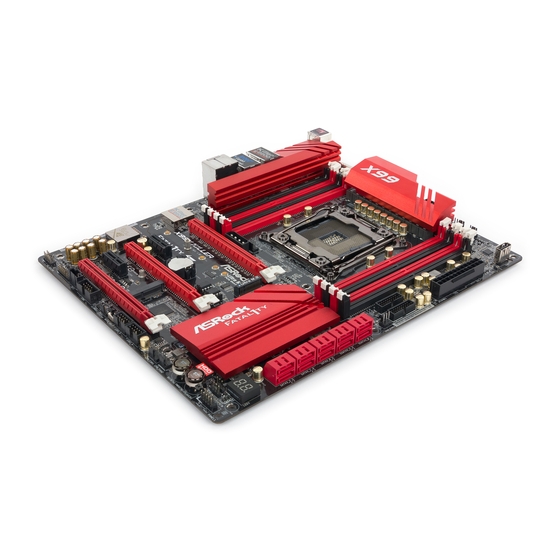
Page 14: Motherboard Layout
1.3 Motherboard Layout CPU_FAN2 CPU_FAN1 ATX12V1 USB7 CLRC BTN1 USB 3.0 T: USB1 B: USB2 2011-3 Socket USB 3.0 Top: T: USB1 RJ-45 B: USB2 USB 3.0 Top: T: USB3 RJ-45 B: USB4 PCIE_PWR1 CHA_FAN3 PWR_FAN1 Killer PCIE1 E2200 X99X Killer Ultra M.2 PCIe Gen3 x4 FATAL... - Page 15 Fatal1ty X99X Killer Series No. Description 2 x 288-pin DDR4 DIMM Slots (DDR4_A1, DDR4_B1) 2 x 288-pin DDR4 DIMM Slots (DDR4_A2, DDR4_B2) ATX 12V Power Connector (ATX12V1) CPU Fan Connector (CPU_FAN1) 2 x 288-pin DDR4 DIMM Slots (DDR4_D2, DDR4_C2) CPU Fan Connector (CPU_FAN2) 2 x 288-pin DDR4 DIMM Slots (DDR4_D1, DDR4_C1) Vertical Type A USB 2.0 (USB7)
- Page 16 No. Description PCIe Power Connector (PCIE_PWR1) Power Fan Connector (PWR_FAN1)
-
Page 17: I/O Panel
Fatal1ty X99X Killer Series 1.4 I/O Panel No. Description No. Description Fatal1ty Mouse Port (USB1) Optical SPDIF Out Port USB 2.0 Port (USB2) USB 3.0 Ports (USB3_34) LAN RJ-45 Port (ASMedia ASM1074 hub) (Qualcomm® Atheros® Killer E2200) USB 3.0 Ports (USB3_12) - Page 18 * here are two LEDs on each LAN port. Please refer to the table below for the LAN port LED indications. ACT/LINK LED SPEED LED LAN Port Activity / Link LED Speed LED Status Description Status Description No Link 10Mbps connection Blinking Data Activity Orange...
-
Page 19: Chapter 2 Installation
Fatal1ty X99X Killer Series Chapter 2 Installation his is an ATX form factor motherboard. Before you install the motherboard, study the coniguration of your chassis to ensure that the motherboard its into it. Pre-installation Precautions Take note of the following precautions before you install motherboard components or change any motherboard settings. -
Page 20: Installing The Cpu
2.1 Installing the CPU 1. Before you insert the 2011-3-Pin CPU into the socket, please check if the PnP cap is on the socket, if the CPU surface is unclean, or if there are any bent pins in the socket. Do not force to insert the CPU into the socket if above situation is found. - Page 21 Fatal1ty X99X Killer Series...
- Page 22 Please save and replace the cover if the processor is removed. he cover must be placed if you wish to return the motherboard for ater service.
-
Page 23: Installing The Cpu Fan And Heatsink
Fatal1ty X99X Killer Series 2.2 Installing the CPU Fan and Heatsink... -
Page 24: Installation Of Memory Modules (Dimm)
2.3 Installation of Memory Modules (DIMM) his motherboard provides eight 288-pin DDR4 (Double Data Rate 4) DIMM slots, and supports Quad Channel Memory Technology. 1. For quad channel coniguration, you always need to install identical (the same brand, speed, size and chip-type) DDR4 DIMM pairs. 2. - Page 25 Fatal1ty X99X Killer Series...
-
Page 26: Expansion Slots (Pci Express Slots)
2.4 Expansion Slots (PCI Express Slots) here are 5 PCI Express slots and 1 mini-PCI Express slot on the motherboard. Before installing an expansion card, please make sure that the power supply is switched of or the power cord is unplugged. Please read the documentation of the expansion card and make necessary hardware settings for the card before you start the installation. - Page 27 Fatal1ty X99X Killer Series PCIe Slot Conigurations (For CPU with 28 PCIe lanes) PCIE1 PCIE2 PCIE3 PCIE4 PCIE5 Single Graphics Card Two Graphics Cards in CrossFireX or SLI Mode hree Graphics Cards in 3-Way CrossFireX Mode *3-Way SLI Mode is not supported for CPU with 28 PCIe lanes.
-
Page 28: Jumpers Setup
2.5 Jumpers Setup he illustration shows how jumpers are setup. When the jumper cap is placed on the pins, the jumper is “Short”. If no jumper cap is placed on the pins, the jumper is “Open”. he illustration shows a 3-pin jumper whose pin1 and pin2 are “Short” when a jumper cap is placed on these 2 pins. -
Page 29: Onboard Headers And Connectors
Fatal1ty X99X Killer Series 2.6 Onboard Headers and Connectors Onboard headers and connectors are NOT jumpers. Do NOT place jumper caps over these headers and connectors. Placing jumper caps over the headers and connectors will cause permanent damage to the motherboard. - Page 30 Serial ATA3 Connectors hese ten SATA3 (SSATA3_0_1: connectors support SATA see p.6, No. 13) data cables for internal (SSATA3_2_3: storage devices with up see p.6, No. 14) to 6.0 Gb/s data transfer (SATA3_0_3: rate. If the eSATA port see p.6, No. 15) on the rear I/O has been (SATA3_1_4: connected, the internal...
- Page 31 Fatal1ty X99X Killer Series Front Panel Audio Header his header is for PRESENCE# MIC_RET (9-pin HD_AUDIO1) connecting audio devices OUT_RET (see p.6, No. 33) to the front audio panel. OUT2_L J_SENSE OUT2_R MIC2_R MIC2_L 1. High Deinition Audio supports Jack Sensing, but the panel wire on the chassis must sup- port HDA to function correctly.
- Page 32 CPU Fan Connectors his motherboard pro- (4-pin CPU_FAN1) vides a 4-Pin CPU fan (see p.6, No. 4) (Quiet Fan) connector. +12V If you plan to connect a CPU_F AN_SPEED FAN_SPEED_CONTROL 3-Pin CPU fan, please (3-pin CPU_FAN2) connect it to Pin 1-3. (see p.6, No.
- Page 33 Fatal1ty X99X Killer Series RRXD1 Serial Port Header his COM1 header DDTR#1 DDSR#1 CCTS#1 (9-pin COM1) supports a serial port (see p.6, No. 30) module. RRI#1 RRTS#1 TTXD1 DDCD#1 TPM Header his connector supports Trusted (17-pin TPMS1) Platform Module (TPM) system, (see p.6, No.
-
Page 34: Smart Switches
2.7 Smart Switches he motherboard has four smart switches: Power Switch, Reset Switch, Clear CMOS Switch and one BIOS Selection Switch, allowing users to quickly turn on/of the system, reset the system, clear the CMOS values or boot from diferent BIOS. Power Switch Power Switch allows users Power... -
Page 35: Dr. Debug
Fatal1ty X99X Killer Series 2.8 Dr. Debug Dr. Debug is used to provide code information, which makes troubleshooting even easier. Please see the diagrams below for reading the Dr. Debug codes. Code Description Please check if the CPU is installed correctly and then clear CMOS. - Page 36 Problem related to USB devices. Please try removing all USB devices. Problem related to memory. Please re-install the CPU and memory then clear CMOS. If the problem still exists, please install only one memory module or try using other memory modules.
-
Page 37: Sli Tm
Fatal1ty X99X Killer Series 2.9 SLI , 3-Way SLI and Quad SLI Operation Guide ® his motherboard supports NVIDIA , 3-Way SLI and Quad SLI (Scalable Link Interface) technology that allows you to install up to three identical PCI ®... - Page 38 Step 3 Align and insert the ASRock SLI_ Bridge_2S Card to the goldingers on each graphics card. Make sure the ASRock SLI_ Bridge_2S Card is irmly in place. SLI_Bridge_2S Card ASRock SLI_Bridge_2S Card Step 4 Connect a VGA cable or a DVI cable to the...
-
Page 39: Installing Three Sli Tm -Ready Graphics Cards
PCI Express graphics card are connected. Repeat this step on the three graphics cards. Step 3 Align and insert the ASRock 3-Way SLI- 2S1S Bridge Card to the goldingers on each graphics card. Make sure the ASRock 3-Way SLI-2S1S Bridge Card is irmly in place. - Page 40 Step 4 Step 4 Connect a VGA cable or a DVI cable to the Connect a VGA cable or a DVI cable to the monitor connector or the DVI connector of monitor connector or the DVI connector of the graphics card that is inserted to PCIE1 the graphics card that is inserted to PCIE1 slot.
-
Page 41: Driver Installation And Setup
Fatal1ty X99X Killer Series 2.9.3 Driver Installation and Setup Install the graphics card drivers to your system. Ater that, you can enable the ® Multi-Graphics Processing Unit (GPU) in the NVIDIA nView system tray utility. Please follow the below procedures to enable the multi-GPU. -
Page 42: Tm And Quad Crossfirex
2.10 CrossFireX , 3-Way CrossFireX and Quad CrossFireX Operation Guide his motherboard supports CrossFireX , 3-way CrossFireX and Quad CrossFireX that allows you to install up to three identical PCI Express x16 graphics cards. Currently CrossFireX , 3-way CrossFireX and Quad ®... - Page 43 Fatal1ty X99X Killer Series Step 3 Connect a VGA cable or a DVI cable to the monitor connector or the DVI connec- tor of the graphics card that is inserted to PCIE1 slot.
-
Page 44: Installing Three Crossfirex
2.10.2 Installing Three CrossFireX -Ready Graphics Cards Step 1 Insert one graphics card into PCIE1 slot, another graphics card to PCIE3 slot, and the other graphics card to PCIE5 slot. Make sure that the cards are properly seated on the slots. Step 2 Use one CrossFire Bridge to connect the graphics cards on PCIE1 and PCIE3... -
Page 45: Driver Installation And Setup
Fatal1ty X99X Killer Series 2.10.3 Driver Installation and Setup Step 1 Power on your computer and boot into OS. Step 2 Remove the AMD drivers if you have any VGA drivers installed in your system. he Catalyst Uninstaller is an optional download. We recommend using this utility to un- install any previously installed Catalyst drivers prior to installation. -
Page 46: M.2_Ssd (Ngff) Module Installation Guide
2.11 M.2_SSD (NGFF) Module Installation Guide he M.2, also known as the Next Generation Form Factor (NGFF), is a small size and versatile card edge connector that aims to replace mPCIe and mSATA. he Ultra M.2 Socket (M2) can accommodate either a M.2 SATA3 6.0 Gb/s module or a M.2 PCI Express module up to Gen3 x4 (32 Gb/s). - Page 47 Fatal1ty X99X Killer Series Step 3 Move the standof based on the module type and length. he standof is placed at the nut location D by default. Skip Step 3 and 4 and go straight to Step 5 if you are going to use the default nut.
- Page 48 Plextor PX-G512M6e ADATA AXNS381E-128GM-B Plextor PX-G256M6e ADATA AXNS381E-256GM-B SanDisk SD6PP4M-128G Crucial CT120M500SSD4/120G SanDisk SD6PP4M-256G Crucial CT240M500SSD4/240G Samsung XP941-512G (MZHPU512HCGL) Intel SSDSCKGW080A401/80G Kingston RBU-SM2280S3/120G For the latest updates of M.2_SSD (NFGG) module support list, please visit our website for details: http://www.asrock.com...
-
Page 49: Hdd Saver Cable Installation Guide
Fatal1ty X99X Killer Series 2.12 HDD Saver Cable Installation Guide The HDD Saver Connector on this motherboard allows you to switch on and off the connected HDDs via sotware when needed. his design secures more privacy, saves more energy, and extends the HDDs' lifespans. Please follow the steps below to install the HDD Saver Cable. -
Page 50: Chapter 3 Software And Utilities Operation
Chapter 3 Software and Utilities Operation 3.1 Installing Drivers he Support CD that comes with the motherboard contains necessary drivers and useful utilities that enhance the motherboard’s features. Running The Support CD To begin using the support CD, insert the CD into your CD-ROM drive. he CD automatically displays the Main Menu if “AUTORUN”... -
Page 51: F-Stream
Fatal1ty X99X Killer Series 3.2 F-Stream F-Stream is ASRock’s multi purpose sotware suite with a new interface, more new features and improved utilities, including XFast RAM, Dehumidiier, Good Night LED, FAN-Tastic Tuning, OC Tweaker and a whole lot more. 3.2.1 Installing F-Stream When you install the all-in-one driver to your system from ASRock’s support CD,... - Page 52 Tools Various tools and utilities. XFast RAM Boost the system’s performance and extend the HDD’s or SDD’s lifespan! Create a hidden partition, then assign which iles should be stored in the RAM drive. Fast Boot Fast Boot minimizes your computer's boot time. Please note that Ultra Fast mode is only supported by Windows 8.1/8 and the VBIOS must support UEFI GOP if you are using an external graphics card.
- Page 53 Fatal1ty X99X Killer Series Dehumidiier Prevent motherboard damages due to dampness. Enable this function and conigure the period of time until the computer powers on, and the duration of the dehumidifying process. Key Master Enhance your mouse and keyboard with customizable macros, sniper modes, scroll speed, key repeat rates and repeat delay.
- Page 54 OC Tweaker Conigurations for overclocking the system. System Info View information about the system. *he System Browser tab may not be available for certain models.
- Page 55 Fatal1ty X99X Killer Series Live Update Check for newer versions of BIOS or drivers. Tech Service Contact Tech Service if you have problems with your computer. Please leave your contact information along with details of the problem.
- Page 56 Settings Conigure ASRock F-Stream. Click to select "Auto run at Windows Startup" if you want F-Stream to be launched when you start up the Windows operating system.
-
Page 57: Killer Network Manager
3.3.1 Installing Killer Network Manager When you install the all-in-one driver to your system from ASRock’s support CD, Killer Network Manager will be auto-installed as well. Ater the installation, you will ind the icon “Killer Network Manager“... - Page 58 Performance Performance allows you to view in real time your system performance and current network utilization for download and upload traic. Network Network allows you to set your preferred upload/download speeds and test the network speed. * You must have Adobe Flash Player installed to run the network speed test.
- Page 59 Fatal1ty X99X Killer Series Killer Ethernet Killer Ethernet displays the network information.
-
Page 60: Asrock App Shop
Double-click on your desktop to access ASRock APP Shop utility. *You need to be connected to the Internet to download apps from the ASRock APP Shop. 3.4.1 UI Overview Category Panel Hot News... -
Page 61: Apps
Fatal1ty X99X Killer Series 3.4.2 Apps When the "Apps" tab is selected, you will see all the available apps on screen for you to download. Installing an App Step 1 Find the app you want to install. he most recommended app appears on the let side of the screen. he other various apps are shown on the right. - Page 62 Step 3 If you want to install the app, click on the red icon to start downloading. Step 4 When installation completes, you can ind the green "Installed" icon appears on the upper right corner. To uninstall it, simply click on the trash can icon *he trash icon may not appear for certain apps.
- Page 63 Fatal1ty X99X Killer Series Upgrading an App You can only upgrade the apps you have already installed. When there is an available new version for your app, you will ind the mark of "New Version" appears below the installed app icon.
-
Page 64: Bios & Drivers
3.4.3 BIOS & Drivers Installing BIOS or Drivers When the "BIOS & Drivers" tab is selected, you will see a list of recommended or critical updates for the BIOS or drivers. Please update them all soon. Step 1 Please check the item information before update. Click on to see more details. -
Page 65: Setting
Fatal1ty X99X Killer Series 3.4.4 Setting In the "Setting" page, you can change the language, select the server location, and determine if you want to automatically run the ASRock APP Shop on Windows startup. -
Page 66: Start8
3.5.1 Installing Start8 Install Start8, which is located in the folder at the following path of the Support CD: \ ASRock Utility > Start8. 3.5.2 Coniguring Start8 Style Select between the Windows 7 style and Windows 8 style Start Menu. hen select... - Page 67 Fatal1ty X99X Killer Series Conigure Conigure provides coniguration options, including icon sizes, which shortcuts you want Start Menu to display, quick access to recently used apps, the functionality of the power button, and more. Control...
- Page 68 Control lets you conigure what a click on the start button or a press on the Windows key does. Desktop Desktop allows you to disable the hot corners when you are working on the desktop. It also lets you choose whether or not the system boots directly into desktop mode and bypass the Metro user interface.
-
Page 69: Xsplit Broadcaster
Fatal1ty X99X Killer Series 3.6 XSplit Broadcaster XSplit Broadcaster is a desktop application designed to make your multimedia broadcasting, live-streaming and recording a lot easier and more fun to do, we are giving away the 3 months premium license which is worth US$24.95 for free! 3.6.1 Live Streaming Your Gameplay... - Page 70 Step 3 Go to Broadcast > Add Channels…. Step 4 Click Add..Step 5 Select a platform for live streaming. *Before you start streaming, you need to register an account for the streaming service website, such as Twitch.tv, USTREAM, or other livestreaming services.
- Page 71 Fatal1ty X99X Killer Series Step 6 Fill in your platform's Username and Password. Based on your needs, conigure the Video and Audio Encoding settings. Click OK. Step 7 he channel then appears in your broadcast list. Click Apply and OK to save the...
-
Page 72: Recording Your Gameplay
Step 8 Go to Broadcast and select the platform to enable live streaming. A link to view your live Broadcast has been copied for you automatically. Simply press CTRL-V or right click and choose Paste to paste the link into the browser, and you can see your broadcast. -
Page 73: Chapter 4 Uefi Setup Utility
Fatal1ty X99X Killer Series Chapter 4 UEFI SETUP UTILITY 4.1 Introduction his section explains how to use the UEFI SETUP UTILITY to conigure your system. You may run the UEFI SETUP UTILITY by pressing <F2> or <Del> right ater you power on the computer, otherwise, the Power-On-Self-Test (POST) will continue with its test routines. -
Page 74: Navigation Keys
4.1.2 Navigation Keys Use < > key or < > key to choose among the selections on the menu bar, and use < > key or < > key to move the cursor up or down to select items, then press <Enter>... -
Page 75: Main Screen
Fatal1ty X99X Killer Series 4.2 Main Screen When you enter the UEFI SETUP UTILITY, the Main screen will appear and display the system overview. Active Page on Entry Select the default page when entering the UEFI setup utility. Full HD UEFI When [Auto] is selected, the resolution will be set to 1920 x 1080 if the monitor supports Full HD resolution. -
Page 76: Oc Tweaker Screen
4.3 OC Tweaker Screen In the OC Tweaker screen, you can set up overclocking features. Because the UEFI sotware is constantly being updated, the following UEFI setup screens and descriptions are for reference purpose only, and they may not exactly match what you see on your screen. -
Page 77: Spread Spectrum
Fatal1ty X99X Killer Series CPU Cache Ratio he CPU Internal Bus Speed Ratio. he maximum should be the same as the CPU Ratio. Minimum CPU Cache Ratio Set the minimum CPU Internal Bus Speed Ratio. BCLK Frequency he CPU speed is determined by the CPU Ratio multiplied with the BCLK. -
Page 78: Dram Coniguration
Short Duration Power Limit Conigure Package Power Limit 2 in watts. When the limit is exceeded, the CPU ratio will be lowered immediately. A lower limit can protect the CPU and save power, while a higher limit may improve performance. Primary Plane Current Limit Conigure the current limit of the CPU under Turbo Mode in ampere. - Page 79 Fatal1ty X99X Killer Series Row Precharge Time (tRP) he number of clock cycles required between the issuing of the precharge command and opening the next row. RAS# Active Time (tRAS) he number of clock cycles required between a bank active command and issuing the precharge command.
- Page 80 Four Activate Window (tFAW) he time window in which four activates are allowed the same rank. CAS Write Latency (tCWL) Conigure CAS Write Latency. Third Timing tREFI Conigure refresh cycles at an average periodic interval. tCKE Conigure the period of time the DDR4 initiates a minimum of one refresh command internally once it enters Self-Refresh mode.
- Page 81 Fatal1ty X99X Killer Series tWRDR Conigure Write to Read diferent rank dead cycle Back to back READ to WRITE from diferent rank separation parameter. tWWDD Conigure Write to Write diferent DIMM dead cycle Back to back READ to WRITE from diferent DIMM separation parameter.
-
Page 82: Fivr Coniguration
ODT PARK (CH C) Conigure the memory on die termination resistors' PARK for channel C. ODT NOM (CH C) Use this to change ODT (CH C) Auto/Manual settings. he default is [Auto]. ODT WR (CH D) Conigure the memory on die termination resistors' WR for channel D. ODT PARK (CH D) Conigure the memory on die termination resistors' PARK for channel D. -
Page 83: Voltage Coniguration
Fatal1ty X99X Killer Series System Agent Voltage Ofset Conigure the voltage for the System Agent. Setting the voltage higher may increase system stability when overclocking. CPU Integrated VR Faults Disable FIVR Faults to raise the threshold to trigger CPU over current protection and over voltage protection for better overclocking capabilities. -
Page 84: Advanced Screen
4.4 Advanced Screen In this section, you may set the conigurations for the following items: CPU Con- iguration, Chipset Coniguration, Storage Coniguration, Super IO Coniguration, ACPI Coniguration, USB Coniguration and Trusted Computing. Setting wrong values in this section may cause the system to malfunction. -
Page 85: Cpu Coniguration
Fatal1ty X99X Killer Series 4.4.1 CPU Coniguration Intel Hyper Threading Technology Intel Hyper hreading Technology allows multiple threads to run on each core, so that the overall performance on threaded sotware is improved. Active Processor Cores Select the number of cores to enable in each processor package. - Page 86 CPU Thermal Throttling Enable CPU internal thermal control mechanisms to keep the CPU from overheat- ing. CPU C States Support Enable CPU C States Support for power saving. It is recommended to keep C3, C6 and C7 all enabled for better power saving. Package C State Support Enable CPU, PCIe, Memory, Graphics C State Support for power saving.
-
Page 87: Chipset Coniguration
Fatal1ty X99X Killer Series 4.4.2 Chipset Coniguration Intel(R) Thunderbolt Enable/Disable the Intel(R) hunderbolt function. VT-d Intel® Virtualization Technology for Directed I/O helps your virtual machine monitor better utilize hardware by improving application compatibility and reliability, and providing additional levels of manageability, security, isolation, and I/O performance. - Page 88 PCI-E ASPM Support his option enables/disables the ASPM support for all CPU downstream devices PCH PCI-E ASPM Support his option enables/disables the ASPM support for all PCH downstream devices Inte(R) Ethernet Connection I218-V Enable or disable the onboard network interface controller (Intel® I218V). Qualcomn Atheros PCIE Ethernet Connection Controller Enable or disable the onboard network interface controller (Qualcomm®...
-
Page 89: Storage Coniguration
Fatal1ty X99X Killer Series 4.4.3 Storage Coniguration Hard Disk S.M.A.R.T. S.M.A.R.T stands for Self-Monitoring, Analysis, and Reporting Technology. It is a monitoring system for computer hard disk drives to detect and report on various indicators of reliability. -
Page 90: Super Io Coniguration
4.4.4 Super IO Coniguration Serial Port Enable or disable the Serial port. Serial Port Address Select the address of the Serial port. PS2 Y-Cable Enable the PS2 Y-Cable or set this option to Auto. -
Page 91: Acpi Coniguration
Fatal1ty X99X Killer Series 4.4.5 ACPI Coniguration Suspend to RAM Select disable for ACPI suspend type S1. It is recommended to select auto for ACPI S3 power saving. PS/2 Keyboard Power On Allow the system to be waked up by a PS/2 Keyboard. -
Page 92: Usb Coniguration
4.4.6 USB Coniguration USB Controller Enable or disable all the USB ports. Intel USB 3.0 Mode Select Intel® USB 3.0 controller mode. Set [Smart Auto] to keep the USB 3.0 driver enabled ater rebooting (USB 3.0 is enabled in BIOS). Set [Auto] to automatically enable the USB 3.0 driver ater entering the OS (USB 3.0 is disabled in BIOS). -
Page 93: Trusted Computing
Fatal1ty X99X Killer Series 4.4.7 Trusted Computing Security Device Support Enable or disable BIOS support for security device. -
Page 94: Tools
4.5 Tools System Browser ASRock System Browser shows the overview of your current PC and the devices connected. OMG (Online Management Guard) Administrators are able to establish an internet curfew or restrict internet access at speciied times via OMG. You may schedule the starting and ending hours of internet access granted to other users. - Page 95 Fatal1ty X99X Killer Series Dehumidiier CPU Fan Setting Conigure the speed of the CPU fan while Dehumidiier is enabled. he higher the value, the faster the fan speed. Max: 255 Min: 1 HDD Saver By connecting your HDDs to the onboard SATA power connector with our special designed power cable, you can switch these HDDs on and of when needed.
-
Page 96: Instant Flash
USB storage device, then downloads and installs the other required drivers automatically. UEFI Tech Service Contact ASRock Tech Service if you are having trouble with your PC. Please setup network coniguration before using UEFI Tech Service. Instant Flash Save UEFI iles in your USB storage device and run Instant Flash to update your UEFI. -
Page 97: Network Coniguration
Fatal1ty X99X Killer Series Network Coniguration Use this to conigure internet connection settings for Internet Flash. Internet Setting Enable or disable sound efects in the setup utility. UEFI Download Server Select a server to download the UEFI irmware. Save User Default Type a proile name and press enter to save your settings as user default. -
Page 98: Hardware Health Event Monitoring Screen
4.6 Hardware Health Event Monitoring Screen his section allows you to monitor the status of the hardware on your system, including the parameters of the CPU temperature, motherboard temperature, fan speed and voltage. CPU Fan 1 & 2 Setting Select a fan mode for CPU Fans 1&2, or choose Customize to set 5 CPU temperatures and assign a respective fan speed for each temperature. - Page 99 Fatal1ty X99X Killer Series Chassis Fan 3 Setting Select a fan mode for Chassis Fan 3, or choose Customize to set 5 CPU temperatures and assign a respective fan speed for each temperature. Chassis Fan 3 Temp Source Select a fan temperature source for Chassis Fan 3.
-
Page 100: Security Screen
4.7 Security Screen In this section you may set or change the supervisor/user password for the system. You may also clear the user password. Supervisor Password Set or change the password for the administrator account. Only the administrator has authority to change the settings in the UEFI Setup Utility. Leave it blank and press enter to remove the password. -
Page 101: Boot Screen
Fatal1ty X99X Killer Series 4.8 Boot Screen his section displays the available devices on your system for you to conigure the boot settings and the boot priority. Fast Boot Fast Boot minimizes your computer's boot time. In fast mode you may not boot from an USB storage device. - Page 102 Full Screen Logo Enable to display the boot logo or disable to show normal POST messages. AddOn ROM Display Enable AddOn ROM Display to see the AddOn ROM messages or conigure the AddOn ROM if you've enabled Full Screen Logo. Disable for faster boot speed. Boot Failure Guard If the computer fails to boot for a number of times the system automatically restores the default settings.
- Page 103 Fatal1ty X99X Killer Series CSM (Compatibility Support Module) Enable to launch the Compatibility Support Module. Please do not disable unless you’re running a WHCK test. If you are using Windows 8.1/8 64-bit and all of your devices support UEFI, you may also disable CSM for faster boot speed.
-
Page 104: Exit Screen
4.9 Exit Screen Save Changes and Exit When you select this option the following message, “Save coniguration changes and exit setup?” will pop out. Select [OK] to save changes and exit the UEFI SETUP UTILITY. Discard Changes and Exit When you select this option the following message, “Discard changes and exit setup?”... -
Page 105: Contact Information
Contact Information If you need to contact ASRock or want to know more about ASRock, you’re welcome to visit ASRock’s website at http://www.asrock.com; or you may contact your dealer for further information. For technical questions, please submit a support request form at http://www.asrock.com/support/tsd.asp...
Need help?
Do you have a question about the Fatal1ty X99X Killer Series and is the answer not in the manual?
Questions and answers