Table of Contents
Advertisement
Advertisement
Table of Contents

Related Manuals for ASROCK X99 Taich


Summary of Contents for ASROCK X99 Taich
-
Page 2: Copyright Notice
(including damages for loss of profits, loss of business, loss of data, interruption of business and the like), even if ASRock has been advised of the possibility of such damages arising from any defect or error in the documentation or product. - Page 3 If you require assistance please call ASRock Tel : +886-2-28965588 ext.123 (Standard International call charges apply) Manufactured under license under U.S.
-
Page 4: Table Of Contents
Chapter 1 Introduction Package Contents Specifications Motherboard Layout I/O Panel WiFi-802.11ac Module and ASRock WiFi 2.4/5 GHz Antenna Chapter 2 Installation Installing the CPU Installing the CPU Fan and Heatsink Installation of Memory Modules (DIMM) Expansion Slots (PCI Express Slots) - Page 5 2.10.3 Driver Installation and Setup 2.11 M.2_SSD (NGFF) Module Installation Guide Chapter 3 Software and Utilities Operation Installing Drivers A-Tuning ASRock Live Update & APP Shop 3.3.1 UI Overview 3.3.2 Apps 3.3.3 BIOS & Drivers 3.3.4 Setting Chapter 4 UEFI SETUP UTILITY...
- Page 6 4.6.5 ACPI Configuration 4.6.6 USB Configuration 4.6.7 Trusted Computing Tools Hardware Health Event Monitoring Screen Security Screen 4.10 Boot Screen 4.11 Exit Screen...
-
Page 7: Chapter 1 Introduction
If you require technical support related to this mother- board, please visit our website for specific information about the model you are using. You may find the latest VGA cards and CPU support list on ASRock’s website as well. ASRock website http://www.asrock.com. -
Page 8: Specifications
• 8 x DDR4 DIMM Slots • Supports DDR4 3300+(OC)*/2933(OC)/2800(OC)/2400 (OC)/2133 non-ECC, un-buffered memory * Please refer to Memory Support List on ASRock's website for more information. (http://www.asrock.com/) • Supports non-ECC RDIMM (Registered DIMM) • Supports DDR4 ECC, un-buffered memory/RDIMM with Intel®... - Page 9 • 7.1 CH HD Audio with Content Protection (Realtek ALC1150 Audio Codec) • Premium Blu-ray Audio support • Supports Surge Protection (ASRock Full Spike Protection) • Supports Purity Sound - Nichicon Fine Gold Series Audio Caps - 115dB SNR DAC with Differential Amplifier - TI®...
- Page 10 • 3 x USB 2.0 Ports (Supports ESD Protection (ASRock Full Spike Protection)) • 1 x USB 3.1 Type-A Port (10 Gb/s) (ASMedia ASM1142) (Supports ESD Protection (ASRock Full Spike Protection)) • 1 x USB 3.1 Type-C Port (10 Gb/s) (ASMedia ASM1142) (Supports ESD Protection (ASRock Full Spike Protection)) • 3 x USB 3.0 Ports (Intel®...
- Page 11 • 1 x Front Panel Audio Connector • 2 x USB 2.0 Headers (Support 4 USB 2.0 ports) (Supports ESD Protection (ASRock Full Spike Protection)) • 1 x USB 3.0 Header (Supports 2 USB 3.0 ports) (Supports ESD Protection (ASRock Full Spike Protection)) • 1 x Dr.
- Page 12 Due to limitation, the actual memory size may be less than 4GB for the reservation for sys- tem usage under Windows® 32-bit operating systems. Windows® 64-bit operating systems do not have such limitations. You can use ASRock XFast RAM to utilize the memory that Windows® cannot use.
-
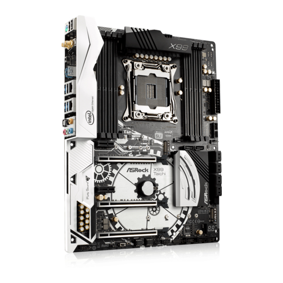
Page 13: Motherboard Layout
X99 Taichi 1.3 Motherboard Layout CPU_FAN1 CPU_OPT/W_PUMP ATX12V1 M2_WIFI CLRC BTN1 USB 3.1 T: USB31_TA_1 B: USB31_TC_1 2011-3 Socket USB 2.0 Top: T: USB7 RJ-45 USB 3.0 B: USB5 USB 3.0 Top: T: USB3 RJ-45 B: USB4 CHA_FAN1 CHA_FAN3 CHA_FAN2 PCIE1 NUT1_3 NUT1_2... - Page 14 No. Description 2 x 288-pin DDR4 DIMM Slots (DDR4_A1, DDR4_B1) 2 x 288-pin DDR4 DIMM Slots (DDR4_A2, DDR4_B2) ATX 12V Power Connector (ATX12V1) CPU Fan Connector (CPU_FAN1) 2 x 288-pin DDR4 DIMM Slots (DDR4_D2, DDR4_C2) 2 x 288-pin DDR4 DIMM Slots (DDR4_D1, DDR4_C1) CPU Optional/Water Pump Fan Connector (CPU_OPT/W_PUMP) ATX Power Connector (ATXPWR1) Chassis Fan Connector (CHA_FAN3)
-
Page 15: I/O Panel
X99 Taichi 1.4 I/O Panel No. Description No. Description USB 2.0 Ports (USB12) USB 3.0 Ports (USB3_34) LAN RJ-45 Port USB 2.0 Port (USB7) (Intel® I211AT)* USB 3.0 Port (USB3_5) LAN RJ-45 Port USB 3.1 Type-A Port (USB31_TA_1) (Intel® I218V)* (ASMedia ASM1142) Central / Bass (Orange) USB 3.1 Type-C Port (USB31_TC_1) - Page 16 * There are two LEDs on each LAN port. Please refer to the table below for the LAN port LED indications. ACT/LINK LED SPEED LED LAN Port Activity / Link LED Speed LED Status Description Status Description No Link 10Mbps connection Blinking Data Activity Orange...
-
Page 17: Wifi-802.11Ac Module And Asrock Wifi 2.4/5 Ghz Antenna
X99 Taichi 1.5 WiFi-802.11ac Module and ASRock WiFi 2.4/5 GHz Antenna WiFi-802.11ac + BT Module This motherboard comes with an exclusive WiFi 802.11 a/b/g/n/ac + BT v4.0 module that offers support for WiFi 802.11 a/b/g/n/ac connectivity standards and Bluetooth v4.0. WiFi + BT module is an easy-to-use wireless local area network (WLAN) adapter to support WiFi + BT. - Page 18 WiFi Antennas Installation Guide Step 1 Prepare the WiFi 2.4/5 GHz Antennas that come with the package. Step 2 Connect the two WiFi 2.4/5 GHz Antennas to the antenna connectors. Turn the antenna clock- wise until it is securely connected. Step 3 Set the WiFi 2.4/5 GHz Antenna as shown in the illustration.
-
Page 19: Chapter 2 Installation
X99 Taichi Chapter 2 Installation This is an ATX form factor motherboard. Before you install the motherboard, study the configuration of your chassis to ensure that the motherboard fits into it. Pre-installation Precautions Take note of the following precautions before you install motherboard components or change any motherboard settings. -
Page 20: Installing The Cpu
2.1 Installing the CPU 1. Before you insert the 2011-3-Pin CPU into the socket, please check if the PnP cap is on the socket, if the CPU surface is unclean, or if there are any bent pins in the socket. Do not force to insert the CPU into the socket if above situation is found. - Page 21 X99 Taichi...
- Page 22 Please save and replace the cover if the processor is removed. The cover must be placed if you wish to return the motherboard for after service.
-
Page 23: Installing The Cpu Fan And Heatsink
X99 Taichi 2.2 Installing the CPU Fan and Heatsink... -
Page 24: Installation Of Memory Modules (Dimm)
2.3 Installation of Memory Modules (DIMM) This motherboard provides eight 288-pin DDR4 (Double Data Rate 4) DIMM slots, and supports Quad Channel Memory Technology. 1. For quad channel configuration, you always need to install identical (the same brand, speed, size and chip-type) DDR4 DIMM pairs. 2. - Page 25 X99 Taichi...
-
Page 26: Expansion Slots (Pci Express Slots)
2.4 Expansion Slots (PCI Express Slots) There are 5 PCI Express slots on the motherboard. Before installing an expansion card, please make sure that the power supply is switched off or the power cord is unplugged. Please read the documentation of the expansion card and make necessary hardware settings for the card before you start the installation. - Page 27 X99 Taichi PCIe Slot Configurations (For CPU with 28 PCIe lanes) PCIE1 PCIE2 PCIE3 PCIE4 PCIE5 Single Graphics Card Two Graphics Cards in CrossFireX or SLI Mode Three Graphics Cards in 3-Way CrossFireX Mode or 3-Way SLI Mode For a better thermal environment, please connect a chassis fan to the motherboard’s chas- sis fan connector (CHA_FAN1, CHA_FAN2 or CHA_FAN3) when using multiple graphics cards.
-
Page 28: Jumpers Setup
2.5 Jumpers Setup The illustration shows how jumpers are setup. When the jumper cap is placed on the pins, the jumper is “Short”. If no jumper cap is placed on the pins, the jumper is “Open”. The illustration shows a 3-pin jumper whose pin1 and pin2 are “Short” when a jumper cap is placed on these 2 pins. -
Page 29: Onboard Headers And Connectors
X99 Taichi 2.6 Onboard Headers and Connectors Onboard headers and connectors are NOT jumpers. Do NOT place jumper caps over these headers and connectors. Placing jumper caps over the headers and connectors will cause permanent damage to the motherboard. System Panel Header Connect the power switch, PLED+ PLED-... - Page 30 Serial ATA3 Connectors These ten SATA3 (SSATA3_0_1: connectors support SATA SSATA3_3 SSATA3_2 see p.7, No. 14) data cables for internal (SSATA3_2: storage devices with up to see p.7, No. 13) 6.0 Gb/s data transfer rate. (SSATA3_3: * The SSATA3_3 connector see p.7, No.
- Page 31 X99 Taichi USB 3.0 Header There is one USB 3.0 header Vbus Vbus (19-pin USB3_1_2) on this motherboard. Vbus IntA_PB_SSRX- IntA_PA_SSRX- IntA_PB_SSRX+ (see p.7, No. 10) IntA_PA_SSRX+ This USB 3.0 header can IntA_PB_SSTX- IntA_PA_SSTX- IntA_PB_SSTX+ support two ports. IntA_PA_SSTX+ IntA_PB_D- IntA_PA_D- IntA_PB_D+ IntA_PA_D+...
- Page 32 FAN_SPEED_CONTROL CPU Fan Connectors This motherboard CPU_FAN_SPEED FAN_VOLTAGE (4-pin CPU_FAN1) provides a 4-Pin CPU fan (see p.7, No. 4) (Quiet Fan) connector. If you plan to connect a 3-Pin CPU fan, please connect it to Pin 1-3. CPU Optional/Water This motherboard FAN_SPEED_CONTROL CPU_FAN_SPEED Pump Fan Connector...
- Page 33 X99 Taichi TPM Header This connector supports Trusted (17-pin TPMS1) Platform Module (TPM) system, (see p.7, No. 22) which can securely store keys, digital certificates, passwords, and data. A TPM system also helps en- hance network security, protects digital identities, and ensures platform integrity.
-
Page 34: Smart Switches
2.7 Smart Switches The motherboard has two smart switches: Clear CMOS Switch and one BIOS Selection Switch, allowing users to quickly clear the CMOS values or boot from different BIOS. Clear CMOS Switch Clear CMOS Switch (CLRCBTN1) allows users to quickly (see p.9, No. -
Page 35: Dr. Debug
X99 Taichi 2.8 Dr. Debug Dr. Debug is used to provide code information, which makes troubleshooting even easier. Please see the diagrams below for reading the Dr. Debug codes. Code Description Please check if the CPU is installed correctly and then clear CMOS. - Page 36 Problem related to USB devices. Please try removing all USB devices. Problem related to memory. Please re-install the CPU and memory then clear CMOS. If the problem still exists, please install only one memory module or try using other memory modules.
-
Page 37: Sli Tm , 3-Way Sli Tm Tm
X99 Taichi 2.9 SLI , 3-Way SLI and Quad SLI Operation Guide ® This motherboard supports NVIDIA , 3-Way SLI and Quad SLI (Scalable Link Interface) technology that allows you to install up to three identical PCI ® Express x16 graphics cards. Currently, NVIDIA and Quad SLI technology ®... - Page 38 Step 3 Align and insert the ASRock SLI_ Bridge_2S Card/ASRock SLI_HB_ Bridge_2S Card to the goldfingers on each graphics card. Make sure the ASRock SLI_Bridge_2S Card/ASRock SLI_HB_ Bridge_2S Card is firmly in place. * Whether to use ASRock SLI_Bridge_2S Card or ASRock SLI_HB_Bridge_2S Card depends on the type of graphics card you use.
-
Page 39: Installing Three Sli
PCI Express graphics card are connected. Repeat this step on the three graphics cards. Step 3 Align and insert the ASRock 3-Way SLI- 2S1S Bridge Card to the goldfingers on each graphics card. Make sure the ASRock 3-Way SLI-2S1S Bridge Card is firmly in place. - Page 40 Step 4 Connect a VGA cable or a DVI cable to the monitor connector or the DVI connector of the graphics card that is inserted to PCIE2 slot.
-
Page 41: Driver Installation And Setup
X99 Taichi 2.9.3 Driver Installation and Setup Install the graphics card drivers to your system. After that, you can enable the ® Multi-Graphics Processing Unit (GPU) in the NVIDIA nView system tray utility. Please follow the below procedures to enable the multi-GPU. Step 1 Double-click the NVIDIA Control Panel ®... -
Page 42: Tm And Quad Crossfirex
2.10 CrossFireX , 3-Way CrossFireX and Quad CrossFireX Operation Guide This motherboard supports CrossFireX , 3-way CrossFireX and Quad CrossFireX that allows you to install up to three identical PCI Express x16 graphics cards. Currently CrossFireX , 3-way CrossFireX and Quad ®... - Page 43 X99 Taichi Step 3 Connect a VGA cable or a DVI cable to the monitor connector or the DVI connec- tor of the graphics card that is inserted to PCIE2 slot.
-
Page 44: Tm -Ready Graphics Cards
2.10.2 Installing Three CrossFireX -Ready Graphics Cards Step 1 Insert one graphics card into PCIE2 slot, another graphics card to PCIE4 slot, and the other graphics card to PCIE5 slot. Make sure that the cards are properly seated on the slots. Step 2 Use one CrossFire Bridge to connect the graphics cards on PCIE2 and PCIE4... -
Page 45: Driver Installation And Setup
X99 Taichi 2.10.3 Driver Installation and Setup Step 1 Power on your computer and boot into OS. Step 2 Remove the AMD drivers if you have any VGA drivers installed in your system. The Catalyst Uninstaller is an optional download. We recommend using this utility to un- install any previously installed Catalyst drivers prior to installation. -
Page 46: M.2_Ssd (Ngff) Module Installation Guide
2.11 M.2_SSD (NGFF) Module Installation Guide The M.2, also known as the Next Generation Form Factor (NGFF), is a small size and versatile card edge connector that aims to replace mPCIe and mSATA. The Ultra M.2 Socket (M2) can accommodate either a M.2 SATA3 6.0 Gb/s module or a M.2 PCI Express module up to Gen3 x4 (32 Gb/s). - Page 47 X99 Taichi Step 3 Move the standoff based on the module type and length. The standoff is placed at the nut location D by default. Skip Step 3 and 4 and go straight to Step 5 if you are going to use the default nut. Otherwise, release the standoff by hand.
- Page 48 SATA3 2280 TM8PS4256GMC105 Team 256GB SATA3 2242 TM4PS4256GMC105 Transcend 256GB SATA3 2242 TS256GMTS400 Transcend 512GB SATA3 2280 TS512GMTS800 Transcend 512GB SATA3 2260 TS512GMTS600 For the latest updates of M.2_SSD (NFGG) module support list, please visit our website for details: http://www.asrock.com...
-
Page 49: Chapter 3 Software And Utilities Operation
X99 Taichi Chapter 3 Software and Utilities Operation 3.1 Installing Drivers The Support CD that comes with the motherboard contains necessary drivers and useful utilities that enhance the motherboard’s features. Running The Support CD To begin using the support CD, insert the CD into your CD-ROM drive. The CD automatically displays the Main Menu if “AUTORUN”... -
Page 50: A-Tuning
3.2 A-Tuning A-Tuning is ASRock’s multi purpose software suite with a new interface, more new features and improved utilities. 3.2.1 Installing A-Tuning A-Tuning can be downloaded from ASRock Live Update & APP Shop. After the installation, you will find the icon “A-Tuning“ on your desktop. Double-click the “A-Tuning“... -
Page 51: System Info
X99 Taichi OC Tweaker Configurations for overclocking the system. System Info View information about the system. *The System Browser tab may not appear for certain models. - Page 52 FAN-Tastic Tuning Configure up to five different fan speeds using the graph. The fans will automatically shift to the next speed level when the assigned temperature is met. Tech Service Contact Tech Service if you have problems with your computer. Please leave your contact information along with details of the problem.
- Page 53 X99 Taichi Settings Configure ASRock A-Tuning. Click to select "Auto run at Windows Startup" if you want A-Tuning to be launched when you start up the Windows operating system.
-
Page 54: Asrock Live Update & App Shop
Double-click on your desktop to access ASRock Live Update & APP Shop utility. *You need to be connected to the Internet to download apps from the ASRock Live Update & APP Shop. 3.3.1 UI Overview Category Panel Hot News... -
Page 55: Apps
X99 Taichi 3.3.2 Apps When the "Apps" tab is selected, you will see all the available apps on screen for you to download. Installing an App Step 1 Find the app you want to install. The most recommended app appears on the left side of the screen. The other various apps are shown on the right. - Page 56 Step 3 If you want to install the app, click on the red icon to start downloading. Step 4 When installation completes, you can find the green "Installed" icon appears on the upper right corner. To uninstall it, simply click on the trash can icon *The trash icon may not appear for certain apps.
- Page 57 X99 Taichi Upgrading an App You can only upgrade the apps you have already installed. When there is an available new version for your app, you will find the mark of "New Version" appears below the installed app icon. Step 1 Click on the app icon to see more details.
-
Page 58: Bios & Drivers
3.3.3 BIOS & Drivers Installing BIOS or Drivers When the "BIOS & Drivers" tab is selected, you will see a list of recommended or critical updates for the BIOS or drivers. Please update them all soon. Step 1 Please check the item information before update. Click on to see more details. -
Page 59: Setting
X99 Taichi 3.3.4 Setting In the "Setting" page, you can change the language, select the server location, and determine if you want to automatically run the ASRock Live Update & APP Shop on Windows startup. -
Page 60: Chapter 4 Uefi Setup Utility
Chapter 4 UEFI SETUP UTILITY 4.1 Introduction This section explains how to use the UEFI SETUP UTILITY to configure your system. You may run the UEFI SETUP UTILITY by pressing <F2> or <Del> right after you power on the computer, otherwise, the Power-On-Self-Test (POST) will continue with its test routines. -
Page 61: Ez Mode
X99 Taichi 4.2 EZ Mode The EZ Mode screen appears when you enter the BIOS setup program by default. EZ mode is a dashboard which contains multiple readings of the system’s current status. You can check the most crucial information of your system, such as CPU speed, DRAM frequency, SATA information, fan speed, etc. -
Page 62: Advanced Mode
4.3 Advanced Mode The Advanced Mode provides more options to configure the BIOS settings. Refer to the following sections for the detailed configurations. To access the EZ Mode, press <F6> or click the "EZ Mode" button at the upper right corner of the screen. -
Page 63: Navigation Keys
X99 Taichi 4.3.2 Navigation Keys Use < > key or < > key to choose among the selections on the menu bar, and use < > key or < > key to move the cursor up or down to select items, then press <Enter>... -
Page 64: Main Screen
4.4 Main Screen When you enter the UEFI SETUP UTILITY, the Main screen will appear and display the system overview. Favorite Display your collection of BIOS items. Press F5 to add/remove your favorite items. -
Page 65: Oc Tweaker Screen
X99 Taichi 4.5 OC Tweaker Screen In the OC Tweaker screen, you can set up overclocking features. Load 4 GHz and XMP OC Setting Please use better CPU cooler for system stability Load Optimized CPU OC Setting You can use this option to load optimized CPU overclocking setting. Please note that overclocking may cause damage to your CPU and motherboard. -
Page 66: Bclk Frequency
CPU Cache Ratio The CPU Internal Bus Speed Ratio. The maximum should be the same as the CPU Ratio. Minimum CPU Cache Ratio Set the minimum CPU Internal Bus Speed Ratio. BCLK Frequency The CPU speed is determined by the CPU Ratio multiplied with the BCLK. Increasing the BCLK will increase the internal CPU clock speed but also affect the clock speed of other components. -
Page 67: Long Duration Maintained
X99 Taichi Long Duration Maintained Configure the period of time until the CPU ratio is lowered when the Long Duration Power Limit is exceeded. Short Duration Power Limit Configure Package Power Limit 2 in watts. When the limit is exceeded, the CPU ratio will be lowered immediately. -
Page 68: Dram Frequency
DRAM Frequency If [Auto] is selected, the motherboard will detect the memory module(s) inserted and assign the appropriate frequency automatically. DRAM Frequency OC Preset If the DRAM frequency is selected, the corresponding DRAM and BCLK frequency for overclocking will be set. Primary Timing CAS# Latency (tCL) The time between sending a column address to the memory and the beginning of the data... - Page 69 X99 Taichi RAS to RAS Delay (tRRD) The number of clocks between two rows activated in different banks of the same rank. RAS to RAS Delay (tRRD_S) The number of clocks between two rows activated in different banks of the same rank.
- Page 70 tCCD Configure back to back CAS to CAS (i.e. READ to RAED or WRITE to WRITE) from same rank separation parameter. tCCD_L Configure back to back CAS to CAS (i.e. READ to RAED or WRITE to WRITE) from same rank separation parameter. tCCD_WR_L Configure back to back CAS to CAS (i.e.
- Page 71 X99 Taichi tRRDD Configure Read to Read different DIMM dead cycle Back to back READ to WRITE from different DIMM separation parameter. tRRDR Configure Read to Read different rank dead cycle Back to back READ to WRITE from different DIMM separation parameter. RTL (CH A) Configure round trip latency for channel A.
-
Page 72: Advanced Setting
Advanced Setting ODT WR (CH A) Configure the memory on die termination resistors' WR for channel A. ODT PARK (CH A) Configure the memory on die termination resistors' PARK for channel A. ODT NOM (CH A) Use this to change ODT (CH A) Auto/Manual settings. The default is [Auto]. ODT WR (CH B) Configure the memory on die termination resistors' WR for channel B. - Page 73 X99 Taichi Memory Test Enable/disable memory test during normal boot. Memory Test On Fast Boot Enable/disable memory test during fast boot. Memory Power Savings Mode Configure CKE and related memory power savings features. Maximum Aggregate Memory Performance Configure the maximum aggregate memory performance. FIVR Configuration CPU Vcore Voltage Mode Auto: For optimized settings.
-
Page 74: Voltage Configuration
Dynamic SVID Control Configure the SVID (Serial Voltage Identification) support. VCCU Voltage Offset Configure the voltage for the VCCU. Setting the voltage higher may increase system stability when overclocking. Voltage Configuration Power Saving Mode Enable Power Saving Mode to reduce power consumption. CPU Input Voltage Configure the voltage for the CPU. - Page 75 X99 Taichi Load User Default Load previously saved user defaults. Save User UEFI Setup Profile to Disk It helps you to save current UEFI settings as an user profile to disk Load User UEFI Setup Profile from Disk You can load previous saved profile from the disk...
-
Page 76: Advanced Screen
4.6 Advanced Screen In this section, you may set the configurations for the following items: CPU Configuration, Chipset Configuration, Storage Configuration, Super IO Configura- tion, ACPI Configuration, USB Configuration and Trusted Computing. Setting wrong values in this section may cause the system to malfunction. UEFI Configuration UEFI Setup Style Select the default mode when entering the UEFI setup utility. -
Page 77: Cpu Configuration
X99 Taichi 4.6.1 CPU Configuration Intel Hyper Threading Technology Intel Hyper Threading Technology allows multiple threads to run on each core, so that the overall performance on threaded software is improved. Processor Cores Active Management Select the number of cores to enable in each processor package. No-Execute Memory Protection Processors with No-Execution Memory Protection Technology may prevent certain classes of malicious buffer overflow attacks. -
Page 78: Intel Virtualization Technology
Intel Virtualization Technology Intel Virtualization Technology allows a platform to run multiple operating systems and applications in independent partitions, so that one computer system can function as multiple virtual systems. Intel Safer Mode Extensions (SMX) Enable/disable the Intel SMX (Safer Mode Extensions). CPU Thermal Throttling Enable CPU internal thermal control mechanisms to keep the CPU from overheat- ing. -
Page 79: Chipset Configuration
X99 Taichi 4.6.2 Chipset Configuration VT-d Intel® Virtualization Technology for Directed I/O helps your virtual machine monitor better utilize hardware by improving application compatibility and reliability, and providing additional levels of manageability, security, isolation, and I/O performance. Above 4G Decoding Enable/disable the 64-bit capable devices to be decoded in above 4G address space. -
Page 80: Front Panel
PCI-E ASPM Support This option enables/disables the ASPM support for all CPU downstream devices PCH PCI-E ASPM Support This option enables/disables the ASPM support for all PCH downstream devices PCH DMI ASPM Support This option enables/disables the ASPM support for all PCH DMI devices. Inte(R) Ethernet Connection I218-V Enable or disable the onboard network interface controller (Intel®... - Page 81 X99 Taichi Onboard Debug Port LED Configure the onboard Dr. Debug LED.
-
Page 82: Storage Configuration
4.6.3 Storage Configuration Hard Disk S.M.A.R.T. S.M.A.R.T stands for Self-Monitoring, Analysis, and Reporting Technology. It is a monitoring system for computer hard disk drives to detect and report on various indicators of reliability. -
Page 83: Super Io Configuration
X99 Taichi 4.6.4 Super IO Configuration Serial Port Enable or disable the Serial port. Serial Port Address Select the address of the Serial port. PS2 Y-Cable Enable the PS2 Y-Cable or set this option to Auto. -
Page 84: Acpi Configuration
4.6.5 ACPI Configuration Suspend to RAM Select disable for ACPI suspend type S1. It is recommended to select auto for ACPI S3 power saving. PS/2 Keyboard Power On Allow the system to be waked up by a PS/2 Keyboard. Ring-In Power On Allow the system to be waked up by onboard COM port modem Ring-In signals. -
Page 85: Usb Configuration
X99 Taichi 4.6.6 USB Configuration USB Controller Enable or disable all the USB ports. Intel USB 3.0 Mode Select Intel® USB 3.0 controller mode. Set [Smart Auto] to keep the USB 3.0 driver enabled after rebooting (USB 3.0 is enabled in BIOS). Set [Auto] to automatically enable the USB 3.0 driver after entering the OS (USB 3.0 is disabled in BIOS). - Page 86 USB Compatibility Patch If your USB devices (i.e. USB mouse or storage) encounter compatibility problems, please enable this option to fix it. Please note that after enabling this option, it is normal that the system will postpone booting up after pressing the power button.
-
Page 87: Trusted Computing
X99 Taichi 4.6.7 Trusted Computing Security Device Support Enable or disable BIOS support for security device. -
Page 88: Tools
In order to prevent users from bypassing OMG, guest accounts without permission to modify the system time are required. UEFI Tech Service Contact ASRock Tech Service if you are having trouble with your PC. Please setup network configuration before using UEFI Tech Service. Easy RAID Installer Easy RAID Installer helps you to copy the RAID driver from the support CD to your USB storage device. - Page 89 X99 Taichi Easy Driver Installer For users that don’t have an optical disk drive to install the drivers from our support CD, Easy Driver Installer is a handy tool in the UEFI that installs the LAN driver to your system via an USB storage device, then downloads and installs the other required drivers automatically.
-
Page 90: Network Configuration
Internet Flash - DHCP (Auto IP), Auto ASRock Internet Flash downloads and updates the latest UEFI firmware version from our servers for you. Please setup network configuration before using Internet Flash. *For BIOS backup and recovery purpose, it is recommended to plug in your USB pen drive before using this function. -
Page 91: Hardware Health Event Monitoring Screen
X99 Taichi 4.8 Hardware Health Event Monitoring Screen This section allows you to monitor the status of the hardware on your system, including the parameters of the CPU temperature, motherboard temperature, fan speed and voltage. Fan-Tastic Tuning Select a fan mode for CPU Fans 1&2, or choose Customize to set 5 CPU temperatures and assign a respective fan speed for each temperature. - Page 92 CPU_OPT Fan / Water Pump Setting Select a fan mode for CPU Optional/Water Pump fan, or choose Customize to set 5 CPU temperatures and assign a respective fan speed for each temperature. CPU_OPT Fan / Water Pump Temp Source Select a fan temperature source for CPU Optional /Water Pump fan. Chassis Fan 1 Setting Select a fan mode for Chassis Fan 1, or choose Customize to set 5 CPU temperatures and assign a respective fan speed for each temperature.
-
Page 93: Security Screen
X99 Taichi 4.9 Security Screen In this section you may set or change the supervisor/user password for the system. You may also clear the user password. Supervisor Password Set or change the password for the administrator account. Only the administrator has authority to change the settings in the UEFI Setup Utility. -
Page 94: Boot Screen
4.10 Boot Screen This section displays the available devices on your system for you to configure the boot settings and the boot priority. Fast Boot Fast Boot minimizes your computer's boot time. In fast mode you may not boot from an USB storage device. Ultra Fast mode is only supported by Windows 8.1 and the VBIOS must support UEFI GOP if you are using an external graphics card. - Page 95 X99 Taichi Full Screen Logo Enable to display the boot logo or disable to show normal POST messages. AddOn ROM Display Enable AddOn ROM Display to see the AddOn ROM messages or configure the AddOn ROM if you've enabled Full Screen Logo. Disable for faster boot speed. Boot Failure Guard If the computer fails to boot for a number of times the system automatically restores the default settings.
-
Page 96: Launch Storage Oprom Policy
CSM (Compatibility Support Module) Enable to launch the Compatibility Support Module. Please do not disable unless you’re running a WHCK test. If you are using Windows 8.1 64-bit and all of your devices support UEFI, you may also disable CSM for faster boot speed. Launch PXE OpROM Policy Select UEFI only to run those that support UEFI option ROM only. -
Page 97: Exit Screen
X99 Taichi 4.11 Exit Screen Save Changes and Exit When you select this option the following message, “Save configuration changes and exit setup?” will pop out. Select [OK] to save changes and exit the UEFI SETUP UTILITY. Discard Changes and Exit When you select this option the following message, “Discard changes and exit setup?”... -
Page 98: Contact Information
Contact Information If you need to contact ASRock or want to know more about ASRock, you’re welcome to visit ASRock’s website at http://www.asrock.com; or you may contact your dealer for further information. For technical questions, please submit a support request form at http://www.asrock.com/support/tsd.asp...
Need help?
Do you have a question about the X99 Taich and is the answer not in the manual?
Questions and answers