
Related Manuals for Data Aire DAMA-01


Summary of Contents for Data Aire DAMA-01
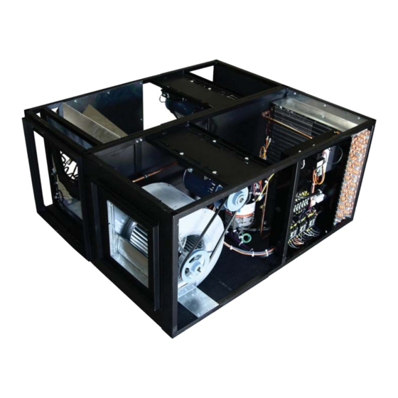
- Page 1 MINI CEILING UNITS Installation, Operation and Maintenance Manual Split System Packaged Unit Packaged Unit...
-
Page 3: Table Of Contents
Table of Contents 1.0 Installation 1.1 Room Considerations ..................6 1.2 Inspection ......................6 1.3 Locating the unit ....................6 1.3.1 Vertical airfl ow units ................7 1.3.2 Air cooled packaged units ..............7 1.3.3 Horizontal airfl ow units................8 1.3.4 Indoor condensers and condensing units .......... - Page 4 4.0 Installation of remote outdoor heat exchanger 4.1 Rigging ......................19 4.2 Leg assembly ....................19 4.3 Locating the remote heat exchanger ............. 19 4.4 Electrical Service ................... 20 4.5 Air cooled condensers - Model DARC ............20 4.5.1 Fan speed control ................20 4.6 Fluid coolers - model DAFC ................
- Page 5 8.5 Fuses ......................33 8.6 Heating elements ................... 33 8.7 Refrigerant fi lter drier ..................33 9.0 Warranty policy ...................... 34 10.0 Contact Data Aire ....................35 11.0 Reference Recommended line sizing for air cooled split systems ........36 Temperature-pressure chart ................37 Superheat and Suction Pressure Trouble Shooting Guide ......
-
Page 6: Installation
1.0 INSTALLATION WARNING: There is no intent on the part of Data Aire, Inc. to defi ne local codes and statutes which may supersede common trade practices. The manufacturer assumes no responsibility for their interpretation. Consult local building codes and the National Electrical Code for special installation requirements. -
Page 7: Vertical Airfl Ow Units
NOTE: There are many available unit confi gurations for Mini Ceiling systems. Be sure to identify the unit type and style before installing. There may be split condenser and con- densing units that require separate or shared power. NOTE: Condensation formation and frequent humidifi er fl ushing (units with humidifi - er) are normal functions of this equipment. -
Page 8: Horizontal Airfl Ow Units
Paperwork Each Data Aire unit ships with start-up sheets that must completed. The start-up sheets are en- closed in packet with the unit. The packet includes the warranty certifi cate, wiring diagrams, specifi c component literature, warranty registration card and a copy of the unit’s Installation/Operation and... -
Page 9: Model Identifi Cation
If equipment is stored for longer than 30 days special precautions must be taken to avoid coil dam- age. All coils should be charged and sealed with a low pressure (less the 25 PSIG) inert gas, such nitrogen. This prevents contaminants from entering the coils. When the seal is broken at installa- tion, the rush of escaping gas verifi... -
Page 10: Piping
Data Aire does not assume this responsibility. The chart covers distances up to 200 equivalent feet. For installations greater than this distance, consult ASHRAE or similar references. -
Page 11: Suction Lines
Common practice for suction line selection and installation should be followed. Suction lines should always be insulated. 2.1.4 Connection Sizes, Air Cooled Units MODEL HOT GAS LINE LIQUID LINE SUCTION LINE DAMA-01 1/2” 1/2” 3/4” DAMA-1.5 1/2” 1/2”... -
Page 12: Field Piping, Remote Condensing Unit
2.1.6 Field Piping, Remote Condensing Unit Water/Glycol Unit Piping The required fi eld installed condenser water pipe sizes may or may not be the same as the connec- tion sizes at the evaporator section or fl uid cooler (refer to Sections 2.2.2 and 2.2.3 for connection sizes). -
Page 13: Connection Sizes - Water/Glycol System
2.2.2 Field Piping, Water/Glycol System 2.2.3 Connection Sizes, Water/Glycol Cooled Units EVAPORATOR WATER IN WATER OUT MODEL CONNECTION CONNECTION DAMW/G-01 3/4” O.D. 3/4” O.D. DAMW/G-1.5 3/4” O.D. 3/4” O.D. DAMW/G-02 3/4” O.D. 3/4” O.D. DAMW/G-2.5 3/4” O.D. 3/4” O.D. 2.2.3 Connection Sizes, Fluid Coolers (Dry Coolers) EVAPORATOR WATER IN WATER OUT... -
Page 14: Auxiliary Chilled Water Coil Piping
Auxiliary Chilled Water Coil Piping Units with an optional Auxiliary Chilled Water cooling coil require a separate source of chilled water. The chilled water connection sizes will be the same as those listed for the condenser water (see chart in Section 2.2.3). Units with optional Energy Saver coil typically have shared or common pip- ing with the condenser supply and therefore do not require a separate cooling source. -
Page 15: Evacuation
In addition to the refrigeration system, check all condenser water lines, humidifi er make-up lines, condensate lines, condensate pumps, chilled water lines, centrifugal pumps and fl uid coolers as applicable. When handling or recovering refrigerant it is not permissible to release refrigerant into the atmo- sphere. -
Page 16: Electrical Connections
Follow the wiring diagrams for each piece of equipment. On most remote heat exchangers the terminals will #30 and #40. All control wiring on Data Aire equipment is 24 VAC. -
Page 17: Remote Shutdown
Remote Shutdown Every Data Aire evaporator has remote contact points available. These are intended for a fi eld sup- plied dry contact or switch to be wired across two terminals. When the contact or switch opens, the control circuit power is interrupted and the unit shuts down, including the control panel. -
Page 18: Mini Dap Iii Units
3.8.2 Mini DAP-III Units The optional Mini DAP-III microprocessor control panel normally comes with the sensors mounted in the display module. Although these existing sensors can be removed for remote mounting, the remote sensor option provides a more convenient means of fi eld installation. When ordered, the remote sensors are shipped with a predetermined length of cable and come mounted in a plastic enclosure. -
Page 19: Installation Of Remote Outdoor Heat Exchanger
INSTALLATION OF REMOTE OUTDOOR HEAT EXCHANGER Air cooled condenser and fl uid coolers have individual Installation, Operation and Mainte- nance manuals which should be referred to for more complete details Rigging The following covers outdoor condensers, condensing units and fl uid coolers. Outdoor heat ex- changers should be moved to their mounting location using a crane or fork lift as applicable. -
Page 20: Electrical Service
Do not locate the heat exchanger in a location that is bordered by tall obstructions (i.e. higher than 10 feet) on no more than two sides. See fi gure for minimum clearance from obstructions and between units. With proper clearance on all sides, two units can be placed side by side. -
Page 21: Energy Saver Cooling
The water-sensing thermostats have adjustable setpoints which are typically staggered to maintain water temperature in a range of 85 to 105°F. This is generally the desired range for glycol cooled systems. A surge tank is standard with all DAFC fl uid coolers. This is suffi cient for most applications. How- ever, an expansion tank should be installed at the at the highest point in the system and the point of least pressure. -
Page 22: Charging
CHARGING Voltage Phase Check 5.1.1 Evaporator Prior to charging, the correct voltage phasing should be checked on the indoor evaporator. Check blower direction on the evaporator by momentarily energizing the fan motor. Reverse any two of the three line voltage wires at the line voltage fi eld connection point to change the blower rotation. Although the scroll compressor is phase dependent, units shipped from the factory are run tested ensuring compressor rotation is consistent with the evaporator fan motor. -
Page 23: Split Indoor Air Cooled Systems Charging - Indoor Condenser
An air cooled package unit may require fi eld charging if a compressor is changed, if a leak devel- ops or if non-condensable are in the system. Field charging should be done by referring to the unit electrical nameplate for the factory charge. Although this value represents the original factory charge, it is still necessary to measure and note proper unit operation including superheat, sub-cooling, head and suction pressure. -
Page 24: Fan Speed Control System Charging - Outdoor Condenser
5.2.3 Fan Speed Control System Charging (with Remote Outdoor Condenser) The standard outdoor air cooled condenser provided by Data Aire has fan speed control. The fan speed controller does not require fi eld adjustment or programming. -
Page 25: Flooded System Charging
NOTE: Charging to a full liquid line sight-glass should never be the sole means of de- termining the correct refrigerant charge. Other parameters such as superheat, suction pressure, head pressure, sub-cooling and ambient temperature are also important. A system charged to a clear sight-glass is often overcharged. 5.2.4 Flooded System Charging Flooded systems include an optional liquid receiver and head pressure control valve for use primar- ily in colder climates. -
Page 26: Water/Glycol Cooled Systems
NOTE: Charging to a full liquid line sight-glass should never be the sole means of de- termining the correct refrigerant charge. Other parameters such as superheat, suction pressure, head pressure, sub-cooling and ambient temperature are also important. A system charged to a clear sight-glass is often overcharged. Water/Glycol Cooled Systems 5.3.1 Water/Glycol Cooled System Charging All water/glycol cooled units are factory charged with refrigerant. -
Page 27: Refrigerant Handling
Refrigerant Handling The use of recovery/recycling is required by the US Environmental Protection Agency (EPA) regu- lations. Technicians who service and dispose of air conditioning and refrigeration equipment must recover the refrigerant instead of venting to the atmosphere. Except for extremely small releases of refrigerant such as those that occur when disconnecting service hoses (diminutive release), a technician who knowing releases or vents refrigerant to the atmosphere is in violation of these regulations. -
Page 28: Glycol Systems
GLYCOL SYSTEMS Glycol Concentration The system must be fi lled with water and the appropriate amount of ethylene or propylene glycol to protect against winter freezing. To achieve the approximate glycol concentration, it is necessary to know the total system volume. The total system volume consists of the fl uid cooler volume, the evaporator unit volume and the volume of the inter-connecting piping. -
Page 29: Freezing Point Or Aqueous Solutions
Freezing Point of Aqueous Solutions Ethylene Glycol Propylene Glycol Percent by Volume Freezing Point °F Percent by Volume Freezing Point °F... -
Page 30: Controls
CONTROLS Standard Thermostat A single stage cooling thermostat is standard on all Mini Ceiling units. Units with either humidifi ers and/or electric reheat require the Mini DAP-II, the Mini DAP-III or the Remote Mount DAP-III. Optional Programmable Thermostat Optional single stage cooling thermostat allows simple programmable functions. Units with either humidifi... -
Page 31: Wiring Diagrams
Mini DAP-II control panel settings are established. Wiring Diagrams Every Data Aire evaporator, condenser, condensing unit or fl uid cooler comes with a wiring diagram. These diagrams are ladder type schematics intended for service personnel. The intent is to allow... -
Page 32: Regular Maintenance Items
REGULAR MAINTENANCE ITEMS Air Filters Air fi lters should be checked on a regular basis and changed when they become dirty. This will ensure effi cient operation of the unit. Spare air fi lters should be kept in stock as these tend to be a frequently replaced maintenance item. -
Page 33: Humidifi Er Canisters
Humidifi er Canisters The optional steam generator type humidifi er does not require maintenance other than to replace the canister as required. The frequency of change will depend on usage and water type. A set of the humidifi er manufacturer’s instructions is included with the paperwork placed inside the unit when it ships. -
Page 34: Warranty Policy
WARRANTY POLICY Seller warrants its equipment to Buyer to be free from defects in material and workmanship for a period of eighteen (18) months from date of shipment, as long as equipment is utilized under normal conditions and service and is properly installed; however, the warranty shall not be applicable to any of the following items: refrigerant, belts, fi... -
Page 35: Contact Data Aire
Tech_Support@dataaire.com Engineering@dataaire.com Sales@dataaire.com Fax: 714-921-6010 Main 714-921-6011 Engineering 714-921-6022 Parts Sales Web Site: www.dataaire.com Job/Unit Information: _______________________________________________________ Data Aire Job Number: _____________________________________________________ Evaporator Serial Number: __________________________________________________ Evaporator Model Number: __________________________________________________ Condenser/Fluid Cooler Serial Number: ________________________________________ Condenser/Fluid Cooler Model Number: _______________________________________... -
Page 36: Recommended Line Sizing For Air Cooled Split Systems
RECOMMENDED LINE SIZING for AIR COOLED SPLIT SYSTEMS HOT GAS LINES – SINGLE CIRCUIT UNITS (Up To 200 Equivalent Feet) Tons per Tonnage Circuit 50 feet 100 feet 150 feet 200 feet LIQUID LINES – SINGLE CIRCUIT UNITS (Up to 200 Equivalent Feet) Tons per Tonnage Circuit... -
Page 37: Temperature-Pressure Chart
TEMPERATURE-PRESSURE CHART R-407C R-410A TEMPERATURE (°F) PRESSURE (PSIG) PRESSURE (PSIG) 43.6 89.7 44.7 91.6 45.9 93.5 47.1 95.5 48.4 97.5 49.6 99.5 50.9 101.6 52.1 103.6 53.4 105.7 54.8 107.9 56.2 110.0 57.5 112.2 58.9 114.4 60.3 116.7 61.7 118.9 63.1 121.2 64.6... -
Page 38: Superheat And Suction Pressure Troubleshooting Guide
Superheat and Suction Pressure Troubleshooting Guide Low Suction Pressure and High Superheat 1. Moisture, wax, dirt in system 2. Undersized valve 3. High superheat adjustment 4. Gas charge condensation 5. Dead thermostatic element charge 6. Wrong thermostatic charge 7. Evaporator pressure drop – no external equalizer 8. -
Page 39: Maintenance/Inspection Checklist
MAINTENANCE/INSPECTION CHECKLIST Evaporator Model Number ___________ Evaporator Serial Number __________________ Technician: _______________________ Date: ___________________________________ Electrical Section ___ Inspect fuses ___ Inspect wire connections ___ Inspect contactors Controls ___ Circle control type: Mini DAP-II Mini DAP-III DAP-III ___ Check unit control operation Check operation of the following: ___ High water alarm ___ Pressure differential switch... - Page 40 Refrigeration Piping ___ Check for lines (leaks/lines secure) ___ Check capillary lines Condensers (Water-Cooled) ___ Check for leaks ___ Entering/leaving water temperatures ENT ____° LVG ____° Compressor ___ Check for oil leaks ___ Check compressor mounting ___ Inspect wire connection ___ Record suction pressure ____ PSIG ___ Record discharge pressure...
- Page 41 Notes ______________________________________________________________________________ ______________________________________________________________________________ ______________________________________________________________________________ ______________________________________________________________________________ ______________________________________________________________________________ ______________________________________________________________________________ ______________________________________________________________________________ ______________________________________________________________________________ ______________________________________________________________________________ ______________________________________________________________________________ ______________________________________________________________________________ ______________________________________________________________________________ ______________________________________________________________________________ ______________________________________________________________________________ ______________________________________________________________________________ ______________________________________________________________________________ ______________________________________________________________________________ ______________________________________________________________________________ ______________________________________________________________________________ ______________________________________________________________________________ ______________________________________________________________________________ ______________________________________________________________________________ ______________________________________________________________________________...
- Page 42 Notes ______________________________________________________________________________ ______________________________________________________________________________ ______________________________________________________________________________ ______________________________________________________________________________ ______________________________________________________________________________ ______________________________________________________________________________ ______________________________________________________________________________ ______________________________________________________________________________ ______________________________________________________________________________ ______________________________________________________________________________ ______________________________________________________________________________ ______________________________________________________________________________ ______________________________________________________________________________ ______________________________________________________________________________ ______________________________________________________________________________ ______________________________________________________________________________ ______________________________________________________________________________ ______________________________________________________________________________ ______________________________________________________________________________ ______________________________________________________________________________ ______________________________________________________________________________ ______________________________________________________________________________ ______________________________________________________________________________...
- Page 44 A Member of the CS Group of Companies © 2011 Data Aire, Inc. Data Aire, Inc. reserves the right to make design changes for the purpose of product improvement or to withdraw any design without notice. DAMAIOM-1010 Rev A...
Need help?
Do you have a question about the DAMA-01 and is the answer not in the manual?
Questions and answers