Sign In
Upload
Manuals
Brands
Data Aire Manuals
Air Conditioner
DAMA-1.5
Data Aire DAMA-1.5 Manuals
Manuals and User Guides for Data Aire DAMA-1.5. We have
2
Data Aire DAMA-1.5 manuals available for free PDF download: Installation, Operation & Maintenance Manual, Installation, Operation And Maintenance Manual
Data Aire DAMA-1.5 Installation, Operation & Maintenance Manual (82 pages)
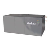
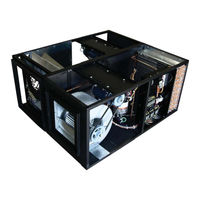
Mini Ceiling Systems
Brand:
Data Aire
| Category:
Accessories
| Size: 2 MB
Table of Contents
Table of Contents
3
Introduction
7
Product Information
7
Model Identification
7
Inspection
8
Paperwork
8
Storage
9
Suggested Reference Storage Room Conditions
9
General Storage Considerations
9
Registered Trademarks - Copy Rights - References Section
10
Installation
11
Recommended Tools for Installation
12
Pre-Installation
12
Installation Must be Planned so that
12
Room Considerations
13
Equipment Handling and Rigging
14
Moving Unit into Final Location
14
Rigging
14
Locating the Unit
14
Horizontal Airflow Units
15
Installing/Mounting
15
Vertical Airflow Units
16
Figure 1 Typical Installation
16
Air Cooled Packaged Units
17
Figure 2 Unit with Vertical Plenum Mounting Method and Condenser Installation
17
Indoor Condensers and Condensing Units
18
Piping
18
Split Air-Cooled Unit Piping
19
Discharge Lines
19
Figure 3 Typical Discharge Check Valve
20
Liquid Lines
21
Suction Lines
21
Recommended Line Sizing
21
Table 1 Line Size Metric Conversion
21
Hot Gas Lines
22
Liquid Lines
22
Suction Lines
22
Table 2 Hot Gas Lines (Inches OD)
22
Table 3 Liquid Lines (Inches OD))
22
Table 4 Suction Lines (Inches OD)
22
Connection Sizes, Air-Cooled Units
23
Connection Sizes, Water/Glycol Cooled Units
23
Connection Sizes, Chilled Water Units
23
Table 5 Connection Sizes, Air-Cooled Units (Inches OD)
23
Table 6 Connection Sizes, Water/Glycol Cooled Units (Inches OD) to Remote Condenser
23
Table 7 Connection Sizes, Chilled Water Units (Inches OD)
23
Field Piping, Remote Condenser/Condensing Unit above Evaporator
24
Field Piping, Remote Condenser/ Condensing Unit below Evaporator
25
Connection Sizes, Fluid Cooler (Dry Cooler)
26
Condensate Drain System
26
Condensate Trap
27
Figure 4 Recommended Condensate Trap Dimensions
28
Condensate Pump Side Mounting Pump (Optional)
29
Figure 5 Typical Side Pump Mounting
29
Humidifier
30
Steam Generator Humidifier
30
Humidifier Piping
30
Refrigerant Piping Protection
30
Water/Glycol Cooled Unit Piping
31
Figure 6 Typical Water/Glycol System
32
Leak Testing
33
Electrical Installation
33
Commissioning Information
34
Electrical Connections
35
General Electrical Field Wiring Guidelines
36
Electrical Service
37
Nameplate Ratings
37
Grounding
37
Voltage Tolerance
37
Three Phase Voltage Tolerance
37
Single-Phase Voltage Tolerance
38
Heat Exchanger Auxiliary Control Wiring
38
Table 8 Three Phase Voltage Tolerance
38
Table 9 Single Phase Voltage Tolerance
38
Remote Shutdown
39
Mini-Dap4 Controller
39
Remote Alarm Contacts
39
Figure 7 Typical Remote Heat Exchanger Interconnection Points
39
Figure 8 Typical Indoor Evaporator Interconnection Points
39
Remote Sensors
40
Condensate Pumps
40
Disconnect Switch (Optional)
40
Table 10 Remote Alarm Contacts Terminals
40
Manual Override Switch Board
41
Figure 9 Manual Override Switch Board
41
Wiring Diagrams
42
Installation of Remote Outdoor Heat Exchanger
42
Charging
43
Package Air-Cooled Systems
43
Charging/Installation Work Procedures
43
Triple Evacuation and Dehydration Procedure
43
Tools Needed
44
First Stage Evacuation
44
Second Stage Evacuation
45
Third Stage Evacuation
45
Final Evacuation Stage
46
General Pre-Charging Guidelines
46
Voltage Phase Check
47
Evaporator Power Phase Check
47
Fixed Speed Scroll Compressor Phase Check
47
Heat Exchanger Phase Check
48
GHRC Air-Cooled Heat Exchanger Phase Check
48
DARC Heat Exchangers Phase Check
48
Line Set Charge Calculations
48
Table 11 Liquid Line Multiplier
48
Component Functional Test
49
Charging Procedures
49
Table 12 Liquid Line Multiplier for R-410A at Various Line Lengths
49
Table 13 Liquid Line Multiplier for R-407C at Various Line Lengths
49
Refrigerant Handling
50
Air-Cooled Split System Charging
50
Table 14 DAMA Starting Charge R-410A
51
Table 15 DAMA Starting Charge R-407C
51
Charging the Fixed Speed Compressor
52
Table 16 Refrigerant Charge Values
53
Additional Oil
54
Flooded System Charging (Systems with Low Ambient Receiver Package)
54
Refrigerant Receiver
55
Applications
55
Selection Guidelines
55
Receiver Location
56
Safety Relief Devices
56
Receiver Installation
56
Figure 10 Typical Low Ambient Receiver Package
57
Charge Fixed Speed Compressor
58
Water/Glycol-Cooled System Charging
58
Table 17 Refrigerant Receiver Charging Chart
58
Table 18 Discharge Head Pressure
58
Table 19 Packaged Units Without Receivers
59
Table 20 Packaged Units with Receivers
59
Important Refrigeration Components
60
Thermal Expansion Valve
60
High Pressure Cutout Switch
60
Low Pressure Cutout Switch
60
Table 21 High Pressure Cutout Switch Setting
60
Table 22 Low Pressure Cutout Switch Setting
60
Liquid Line Solenoid Valve
61
Glycol Systems
62
Glycol Concentration
62
Internal (Fluid) Volume
62
Fluid Cooler Internal Volume
62
Brazed-Plate Fin Condensers
62
Table 23 Mini Ceiling Unit Internal (Fluid) Volume
62
Water Treatment
63
Fluid Cooler
64
Type L Copper Tubing Internal Volume
65
Freezing Point of Aqueous Solutions
65
Mixing Glycol and Water
65
Table 24 Type L Copper Tubing Internal Volume
65
Table 25 Freezing Point of Aqueous Solutions
65
Controls
67
Programmable Thermostat
67
Mini-Dap4 Microprocessor Control Controller
67
Optional Expanded Dap4 Microprocessor Controller
67
Remote Heat Exchangers
67
Regular Maintenance Items
68
Air Filters
68
Belts
68
Bearings
68
Fuses
69
Electric Reheat (Optional)
69
Humidifier (Optional)
69
Humidifier Canisters
69
Refrigerant Filter Drier
69
EC Plenum (Plug) Fans
70
Electronically Commutated Motors
70
EC Motor Testing
71
Maintenance/Inspection Checklist
72
Frequently Asked Questions - FAQ
75
Electrical FAQ Section
75
Mechanical FAQ Section
76
Figure 11 Example Remote EPO Switch Connection
76
Contact Data Aire
79
Advertisement
Data Aire DAMA-1.5 Installation, Operation And Maintenance Manual (44 pages)
MINI CEILING UNITS
Brand:
Data Aire
| Category:
Air Conditioner
| Size: 0 MB
Table of Contents
Table of Contents
3
1 Installation
6
Room Considerations
6
Inspection
6
Locating the Unit
6
Air Cooled Packaged Units
7
Vertical Airfl Ow Units
7
Horizontal Airfl Ow Units
8
Indoor Condensers and Condensing Units
8
Paperwork
8
Storage
8
Model Identifi Cation
9
2 Piping
10
Split Air Cooled Unit Piping
10
Discharge Lines
10
Liquid Lines
10
Piping 2.1 Split Air Cooled Unit Piping
10
Suction Lines
11
Connection Sizes, Aif Cooled Units
11
Field Piping, Remote Condenser
11
Field Piping, Remote Condensing Unit
12
Water/Glycol Unit Piping
12
Field Piping - Water/Glycol System
12
Connection Sizes - Fl Uid Coolers (Dry Coolers)
13
Connection Sizes - Water/Glycol System
13
Auxiliary Chilled Water Coil Piping
14
Condensate Drain Piing
14
Humidifi er Piping
14
Leak Testing
14
Evacuation
15
3 Electrical Connections
16
Electrical Service
16
Nameplate Rating
16
Grounding
16
Voltage Tolerance
16
Auxiliary Control Wiring
16
Remote Shutdown
17
Remote Alarm Contacts
17
Mini DAP II Units
17
Mini DAP III Units
17
Remote Sensors
17
Mini DAP III Units
18
Condensate Pumps
18
4 Installation of Remote Outdoor Heat Exchanger
19
Rigging
19
Leg Assembly
19
Locating the Remote Heat Exchanger
19
Electrical Service
20
Air Cooled Condensers - Model DARC
20
Fan Speed Control
20
Fluid Coolers - Model DAFC
20
Fluid-Sensing Thermostats
20
Energy Saver Cooling
21
5 Charging
22
Voltage Phase Check
22
Evaporator
22
Secondary Heat Exchanger
22
Air Cooled Systems
22
Charging 5.1 Voltage Phase Check
22
Package Air Cooled Systems
22
Split Indoor Air Cooled Systems Charging - Indoor Condenser
23
Fan Speed Control System Charging - Outdoor Condenser
24
Flooded System Charging
25
Water/Glycol Cooled Systems
26
Factor Charge for Water/Glycol Cooled Systems
26
Water/Glycol Cooled System Charging
26
Refrigerant Handling
27
Important Refrigeration Components
27
Expansion Valve
27
High Pressure Cutout Switch
27
Low Pressure Cutout Switch
27
6 Glycol Systems
28
Glycol Concentrations
28
Internal (Fl Uid) Volume
28
Fluid Cooler Internal Volume
28
Copper Piping Internal Volume
28
Freezing Point or Aqueous Solutions
29
7 Controls
30
Standard Thermostat
30
Optional Programmable Thermostat
30
Optional Mini DAP II Microprocessor Control Panel
30
Optional Mini DAP III Microprocessor Control Panel
30
Optional DAP III
30
Controls 7.1 Standard Thermostat
30
Wiring Diagrams
31
8 Regular Maintenance Items
32
Air Fi Lters
32
Belts
32
Bearings
32
Humidifi er Canisters
33
Fuses
33
Heating Elements
33
Refrigerant Fi Lter Drier
33
9 Warranty Policy
34
10 Contact Data Aire
35
11 0 Reference
36
Recommended Line Sizing for Air Cooled Split Systems
36
Temperature-Pressure Chart
37
Superheat and Suction Pressure Troubleshooting Guide
38
Maintenance/Inspection Checklist
39
Advertisement
Related Products
Data Aire DAMA-01
Data Aire DAMA-2.5
Data Aire DAMA-02
Data Aire DAMW/G-01
Data Aire DAMW/G-1.5
Data Aire DAMW/G-02
Data Aire DAMW/G-2.5
Data Aire DALW 08
Data Aire DALW 10
Data Aire DALG 13
Data Aire Categories
Air Conditioner
Accessories
Control Systems
Control Unit
Controller
More Data Aire Manuals
Login
Sign In
OR
Sign in with Facebook
Sign in with Google
Upload manual
Upload from disk
Upload from URL