
Related Manuals for Data Aire LCS


Summary of Contents for Data Aire LCS
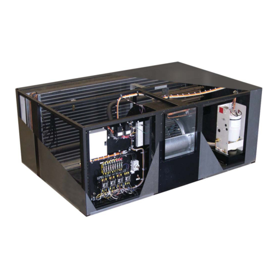
- Page 1 Installation, Operation and Maintenance Manual 6, 8, 10 and 13 ton Air, Water and Glycol Cooled DX and Chilled Water...
- Page 2 Congratulations! You have selected a Data Aire precision control system, one of the fi nest available in the market today. Proper installation, operation and maintenance of this equipment will ensure years of optimal performance. This manual is intended to assist trained service personnel by providing necessary guidelines for this particular equipment.
-
Page 3: Table Of Contents
Table of Contents 1.0 INSTALLATION ......................6 1.1 Room Considerations ....................6 1.2 Inspection ........................6 1.3 Locating the Unit ......................6 1.3.1 Horizontal Airfl ow Units .....................7 1.3.2 Vertical Airfl ow Units ....................7 1.4 Paperwork........................7 1.5 Storage ...........................8 1.6 Model Identifi cation ......................8 2.0 PIPING ........................9 2.1 Split Air Cooled Unit Piping .....................9... - Page 4 Table of Contents, continued 4.0 INSTALLATION OF REMOTE OUTDOOR HEAT EXCHANGER - (continued) 4.5 Air Cooled Condensers - Model DARC ................18 4.5.1 Fan Speed Control ....................... 18 4.5.2 Ambient Thermostats ....................18 4.6 Fluid Coolers - Model DAFC ....................19 4.6.1 Fluid-Sensing Thermostats ..................
-
Page 5: Table Of Contents, Continued
8.5 Fuses ..........................28 8.6 Heating Elements ......................28 8.7 Refrigerant Filter Drier ...................... 28 9.0 WARRANTY ........................ 29 10.0 CONTACT DATA AIRE ................... 30 Line Sizing Chart ........................31 Monthly Maintenance Inspection Checklist ................32 Quarterly Maintenance Inspection Checklist ................33 Superheat and Suction Pressure Troubleshooting Guide ............ -
Page 6: Installation
1.0 INSTALLATION There is no intent on the part of Data Aire, Inc. to defi ne local codes or statutes which may supersede common trade practices. The manufacturer assumes no responsibility for their interpretation. Consult local building codes and the National Electrical Code for special installation requirements. -
Page 7: Horizontal Airfl Ow Units
1.3.1 Horizontal Airfl ow Units All LCS units have horizontal airfl ow confi guration with a 29.5” tall evaporator section. Duct collars are factory provided for the supply and return air. Four threaded support rods must be securely attached to the building structure. Two fi eld provided support channels connect to the pairs of threaded support rod. -
Page 8: Storage
It is the responsibility of the installing contractor to return the start-up sheet and warranty registration card to Data Aire for proper activation of the unit warranty. Failure to do so may cause delays and in some cases void the warranty. -
Page 9: Piping
Data Aire does not assume this responsibility. The chart covers distances up to 200 equivalent feet. For installations greater than this distance, consult ASHRAE or similar references. -
Page 10: Connection Sizes, Air Cooled Units
2.1.4 Connection Sizes Air Cooled Units Model Circuiting Hot Gas Liquid Suction DALA 06 Single circuit 1/2” 1/2” 3/4” DALA 08 Single circuit 3/4” 5/8” 1 1/8” DALA 10 Single circuit 3/4” 5/8” 1 1/8” DALA 13 Single circuit 3/4” 5/8”... -
Page 11: Field Piping, Remote Condenser
2.1.5 Field Piping, Remote Condenser 2.1.6 Field Piping, Remote Condensing Unit... -
Page 12: Water/Glycol Cooled Unit Piping
Water/Glycol Cooled Unit Piping The required fi eld installed condenser water pipe sizes may or may not be the same as the connection sizes at the evaporator or fl uid cooler. (Refer to 2.1.4 for connection sizing.) This will depend on the length of pipe and the calculated pressure drop of peripheral components. -
Page 13: Auxiliary Chilled Water Coil Piping
Auxiliary Chilled Water Coil Piping Units with an Auxiliary Chilled Water cooling coil require a separate source of chilled water. These chilled water connection sizes will be equal to the condenser water connection sizes on the chart in Section 2.1.4. Units with an Energy Saver cooling coil typically have shared piping with the condenser supply and therefore do not require a separate water source. -
Page 14: Leak Testing
Leak Testing No installation is complete until the entire system has been thoroughly checked for leaks. This includes checking refrigerant tubing, fl are fi ttings, pressure controls, shrader fi ttings and compressor rotolock service valves. Check both fi eld and factory connections. In addition to the refrigeration system, check all condenser water lines, humidifi... -
Page 15: Electrical Connections
On most remote heat exchangers the terminals will be #39 and #40. All control wiring on Data Aire equipment is 24 VAC. Condensing units (compressors mounted in condenser) typically require more wires. Refer to wiring diagrams in the unit. -
Page 16: Remote Shutdown
Remote Shutdown Every Data Aire evaporator has remote shutdown contacts points available. This is intended for a fi eld supplied dry contact or switch to be wired across two terminals. When the contact or switch opens, the control circuit power is interrupted and the unit shuts down, including the control panel. -
Page 17: Installation Of Remote Outdoor Heat Exchanger
4.0 INSTALLATION OF REMOTE OUTDOOR HEAT EXCHANGER Air cooled condensers and fl uid coolers have individual Installation, Operation and Maintenance manuals which should be referred to for more complete details. Rigging This section covers outdoor condensers/condensing units and fl uid coolers. Outdoor heat exchangers should be moved to their (typically rooftop) mounting location using a crane or fork lift. -
Page 18: Electrical Service
Noise factors should be also considered when locating an air cooled heat exchanger. Proximity to windows, walls, and surrounding structures can cause objections by the occupants. An acoustical expert should be consulted when noise is of a particular concern. Air cooled heat exchangers should be placed at a level that is higher than the indoor evaporator. -
Page 19: Fluid Coolers - Model Dafc
Typical settings for the ambient thermostats are as follows: Number of fans Header fan Fan 2 Fan 3 Fan 4 Fan 5 65° 75° 65° 75° 85° 65° 65° 85° 75° 50° Fluid Coolers - Model DAFC 4.6.1 Fluid-Sensing Thermostats Fluid cooler fan motors are cycled on and off by individual water-sensing thermostats strapped to the leaving water header. -
Page 20: Charging
It is likely that more refrigerant will be required to complete the charging procedure. Make sure all hoses are properly purged. Review the model number carefully because LCS units are available with either single or dual compressors. Before starting a compressor, the crankcase heater should be energized for a minimum of 12 hours to reduce the possibility of liquid slugging on start-up. -
Page 21: Fan Speed Control System Charging
A system charged to a clear sight glass is often overcharged. 5.2.2. Fan Speed Control System Charging The standard outdoor air cooled condenser for Data Aire equipment is a Fan Speed Control system. After the fi eld refrigerant piping is properly completed, connect the refrigerant drum to the low side and charge with vapor. -
Page 22: Water/Glycol Cooled Systems
the refrigerant tank and set it for liquid feed. Open the refrigerant tank valve and purge the line a the manifold. Open the high side valve on the manifold only and allow the refrigerant to fl ow until the system pressure equalizes. At this point the system will have 78 - 85% of the total refrigerant charge. -
Page 23: Refrigerant Handling
should be 33° F or higher. The superheat at the compressor suction line at least 6 inches away from the compressor should be 8-15° F. Field charging water/glycol systems should be done by referring to the unit electrical nameplate for the factory charge. -
Page 24: High Pressure Cutout Switch
5.5.2. High Pressure Cutout Switch Each refrigerant circuit is protected by a high head pressure cutout switch with a manual reset button. The cutout pressure rating for refrigerant R-407c is 400 psi. Physical location is near the compressor which may be either in the evaporator or the condensing section. 5.5.3. -
Page 25: Copper Piping Internal Volume
Degree F 7.0 CONTROLS Mini dap®4 Microprocessor Controller The Mini dap4 microprocessor controller is the standard controller on the LCS equipment. There is a separate manual that goes into extensive detail regarding functions, features, programming and troubleshooting. The Mini dap4 microprocessor controller has an entire manual dedicated to its use and operation. -
Page 26: Wiring Diagrams
7.4 Wiring Diagrams Every Data Aire evaporator, condenser, condensing unit or fl uid cooler comes with a wiring diagram. These diagrams are ‘ladder”- type schematics intended for service personnel. The intent is to allow the technician to understand the wiring details associated with the electrical components and how they interface with the controls as well as peripheral equipment, including secondary heat exchangers. -
Page 27: Regular Maintenance Items
8.3 Bearings LCS units with either one (1) and two (2) HP motors have permanent lubricated bearings. Motors of three (3) HP and above have a pillow block bearing that must be greased quarterly, or as needed. -
Page 28: Fuses
Fuses Always replace fuses with those of the equivalent rating with regard to: 1) amperage, 2) voltage, and 3) speed. For instance compressors and motors are inductive loads which require time delay fuses. Electric reheat and humidifi ers are resistive loads requiring fast acting fuses. Heating Elements Heating elements do not normally require maintenance. -
Page 29: Warranty
9.0 Warranty Policy Seller warrants its equipment to Buyer to be free from defects in material and workmanship for a period of eighteen (18) months from date of shipment, as long as equipment is utilized under normal conditions and service and is properly installed; however, the warranty shall not be applicable to any of the following items: refrigerant, belts, fi... -
Page 30: Contact Data Aire
E-mail: tech_support@dataaire.com Technical Support engineering@dataaire.com Engineering sales@dataaire.com Sales Web site: www.dataaire.com Job Information: Data Aire Job Number: ________________________________________ Evaporator Serial Number: _____________________________________ Evaporator Model Number: _____________________________________ Condenser/Condensing Unit/ Fluid Cooler Serial Number: _________________________________ Condenser/Condensing Unit Fluid Cooler Model Number: _________________________________... -
Page 31: Line Sizing Chart
RECOMMENDED LINE SIZING FOR AIR COOLED SPLIT SYSTEMS UP TO 200 EQUIVALENT FEET HOT GAS LINES SINGLE CIRCUIT SYSTEMS DUAL CIRCUIT SYSTEMS Unit Tons per EQUIVALENT FEET Unit Tons per EQUIVALENT FEET Tonnage Circuit Tonnage Circuit 7/8 1-1/8 1-1/8 1-1/8 1-1/8 1-1/8 1-3/8 1-3/8 7/8 1-1/8 1-1/8 1-1/8 1-3/8 1-3/8... -
Page 32: Monthly Maintenance Inspection Checklist
Data Aire, Inc. Monthly Maintenance Inspection Checklist Model No. __________________ Serial No. ____________________ Prepared by: _______________ Date: ___ / ___/ 201__ Steam Generating Humidifi er (if applicable) Air Filters ___ Check canister for deposits and water level ___ Check for restricted air fl ow... -
Page 33: Quarterly Maintenance Inspection Checklist
Data Aire, Inc. Quarterly Maintenance Inspection Checklist Model No. _______________________ Serial No. ___________________________ Prepared by: _____________________ Date: ___ / ___/ 201__ Steam Generating Humidifi er (if applicable) Air Filters ____ Check canister for deposits and water level ____ Check for restricted air fl ow ____ Check condition of steam hose and clamps ____ Check fi... -
Page 34: Superheat And Suction Pressure Troubleshooting Guide
2. Poor air distribution 3. Poor refrigerant distribution 4. Improper compressor-evaporator balance 5. Evaporator oil logged 6. Flow from one TXV affecting another’s bulb * Data Aire has ensured that valves are sized properly as the unit ships from the factory. -
Page 35: Temperature Pressure Chart For R-407C And R-410A
Temperature Pressure Chart Temperature (°F) R-407c R-410a 43.6 89.7 44.7 91.6 45.9 93.5 47.1 95.5 48.4 97.5 49.6 99.5 50.9 101.6 52.1 103.6 53.4 105.7 54.8 107.9 53.2 110.0 57.5 112.2 58.9 114.4 60.3 116.7 61.7 118.9 63.1 121.2 64.6 123.6 66.1 125.9... -
Page 36: Index
Fluid Coolers ........10 Freezing Point, Aqueous Solutions..25 Water/Glycol Cooled Units ....10 Fuses ............28 Contact Data Aire ........30 Controls Glycol Concentration ....... 24 Mini dap4 Contoller ......25 Glycol Systems ....12, 15, 19, 20, 23 dap4 Controller........ - Page 37 Humidifi er Canister ........13, 27 Sight Glass ...... 19, 20, 21, 22, 23 Steam Generator Humidifi er ..13, 27 Start Up Sheet ........... 7 Storage ............8 Inspection ..........6 Strainer ............ 12 Installation ..........6 Subcooling ......20, 21, 22, 23 Internal Volume see Volume Suction Lines ......
- Page 38 A Member of the CS Group of Companies © 2011 Data Aire, Inc. Data Aire, Inc. reserves the right to make design changes for the purpose of product improvement or to withdraw any design without notice. DALAIOM-1209 Rev D...
Need help?
Do you have a question about the LCS and is the answer not in the manual?
Questions and answers
I **** looking for the user manual for a Data Aire CRAC unit, model DGTU-0534 serial 2011-3545-B I **** with the Mpls V.A. Medical Center.