Furuno GP-170 Operator's Manual
Hide thumbs
Also See for GP-170:
- Installation manual (67 pages) ,
- Operator's manual (2 pages) ,
- Operator's manual (2 pages)
Table of Contents
Advertisement
Quick Links
Download this manual
See also:
Installation Manual
Advertisement
Table of Contents
Troubleshooting

Related Manuals for Furuno GP-170


Summary of Contents for Furuno GP-170
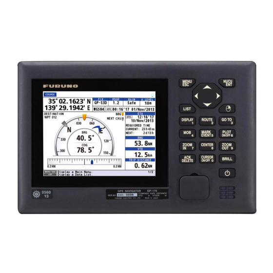
- Page 1 OPERATOR'S MANUAL GPS NAVIGATOR GP-170 Model www.furuno.com...
- Page 2 The paper used in this manual is elemental chlorine free. ・FURUNO Authorized Distributor/Dealer 9-52 Ashihara-cho, Nishinomiya, 662-8580, JAPAN A : JUN 2014 Printed in Japan All rights reserved. Pub. No. OME-44820-A (YOTA ) GP-170 0 0 0 1 7 7 7 3 6 1 0...
-
Page 3: Important Notice
How to discard a used battery Some FURUNO products have a battery(ies). To see if your product has a battery(ies), see the chapter on Maintenance. Follow the instructions below if a battery(ies) is used. Tape the + and - terminals of battery before disposal to prevent fire, heat generation caused by short circuit. -
Page 4: Safety Instructions
Caution Label(s) Caution label(s) is(are) attached to the equipment. Do not remove the label(s). If a label is missing or damaged, contact a FURUNO agent or dealer about replacement. Name: Caution Label... -
Page 5: Table Of Contents
TABLE OF CONTENTS FOREWORD........................vi SYSTEM CONFIGURATIONS..................vii OPERATIONAL OVERVIEW .................1-1 1.1 Controls ........................1-1 1.2 How to Turn the Power On/Off ...................1-3 1.3 How to Adjust the Brilliance of the Display and Panel..........1-4 1.4 How to Select the Display Mode.................1-5 1.5 Main Menu Overview....................1-8 1.6 List Overview ......................1-9 1.7 Context Menu Overview ...................1-10... - Page 6 TABLE OF CONTENTS 4.1.1 How to preset the settings for routes ............. 4-1 4.1.2 How to create a new route with the cursor and the ROUTE key....4-3 4.1.3 How to create a new route from the route list ..........4-4 4.2 How to Edit a Route ....................
- Page 7 TABLE OF CONTENTS 9.3.3 How to set the positioning condition ...............9-5 9.3.4 How to select the RAIM function ..............9-6 9.3.5 How to select the datum .................9-7 9.3.6 How to set the initial position ................9-7 9.3.7 How to set the positioning cycle ..............9-8 9.3.8 How to turn the anti-multipath mode on/off ............9-8 9.4 Beacon/SBAS Menu....................9-9...
-
Page 8: Foreword
• High-resolution color LCD • Comprehensive navigation data displays • A DGPS beacon receiver (internal or external) can be connected to the GP-170 to add DGPS capability. • Storage for 1,000 waypoints, 100 routes (99 for creating, one for external input), 1,000 tracks and 2,000 marks •... -
Page 9: System Configurations
SYSTEM CONFIGURATIONS Basic configuration is shown with solid line. Single configuration Antenna Unit Antenna Unit Antenna Unit GPA-021S* GPA-020S** GPA-017S** *: w/internal beacon receiver **: w/o internal beacon receiver Switching Hub USB Flash Memory MENU NU/CU HUB-100 LIST Radar, DISPLAY ROUTE GO TO Echo Sounder,... - Page 10 SYSTEM CONFIGURATIONS Dual configuration Antenna Unit Antenna Unit Antenna Unit Antenna Unit Antenna Unit Antenna Unit GPA-021S* GPA-020S** GPA-017S** GPA-021S* GPA-020S** GPA-017S** *: w/internal beacon receiver **: w/o internal beacon receiver Switching Hub HUB-100 MENU NU/CU MENU NU/CU USB Flash Memory USB Flash Memory LIST LIST...
-
Page 11: Operational Overview
OPERATIONAL OVERVIEW Controls Operation keys MENU NU/CU MENU NU/CU LIST LIST DISPLAY ROUTE GO TO DISPLAY ROUTE GO TO MARK PLOT EVENT ON/OFF 6 ZOOM CENTER ZOOM MARK PLOT EVENT ON/OFF 6 CURSOR BRILL DELETE ON/OFF 0 ZOOM ZOOM CENTER CURSOR BRILL DELETE... - Page 12 1. OPERATIONAL OVERVIEW Function Control Menu screen Display mode DISPLAY/1 • Selects and confirms the Selects the display mode. selected menu item. ROUTE/2 Starts/stops the registration of a route • Enters a numeric character. on the plotter display. GO TO/3 •...
-
Page 13: How To Turn The Power On/Off
Last-used screen (example: plotter display) DGPS beacon receiver The GP-170 is available in two specifications, with DGPS beacon receiver and no DGPS beacon receiver. Only the beacon receiver equipped GP-170 has DGPS capa- bility. To get DGPS capability, install the optional internal beacon receiver (name: bea- con receiver set, type: OP20-42, code no.: 000-023-637) or connect an external... -
Page 14: How To Adjust The Brilliance Of The Display And Panel
1. OPERATIONAL OVERVIEW Indication System 2D positioning 3D positioning GP-D2D GP-D3D GPS + Differential GP-D2D (Yellow) GP-D3D (Yellow) GPS + Differential (WER>10%) GP-D2D! (Yellow) GP-D3D! (Yellow) GPS + Differential (Unmonitored) GA-2D GA-3D GALILEO GA-S2D GA-S3D GALILEO + SBAS GA-D2D GA-D3D GALILEO + Differential GA-D2D (Yellow) GA-D3D (Yellow) -
Page 15: How To Select The Display Mode
1. OPERATIONAL OVERVIEW Note 1: The default settings for night mode is 6 for [Display] and 7 for [Panel]. If the display is difficult to see when switching to the night mode, use the cursorpad ( ) to increase the display brilliance. Note 2: Whenever the brilliance mode is changed, the last-used brilliance for the se- lected mode is set. -
Page 16: Plotter Display
1. OPERATIONAL OVERVIEW Plotter Display Spinner rotates when This icon appears Distance for RAIM reliability This icon appears when the number the equipment is during the of satellites used for positioning is HDOP: 2D functioning normally. synchronization more than four and the high preci- PDOP: 3D Status with ECDIS. - Page 17 1. OPERATIONAL OVERVIEW Highway Display Course over ground Speed over ground Course information Waypoint Attitude gauge Weather data Course Display Estimated time and date of arrival Range Velocity to destination Trip distance Cross track distance indication...
-
Page 18: Main Menu Overview
1. OPERATIONAL OVERVIEW Data Display Note: When invalid data is input, “- - - -” is displayed. Main Menu Overview 1. Press the MENU/ESC key to open the main menu. These marks indicate additional menus. Basic operation or alert information 2. -
Page 19: List Overview
1. OPERATIONAL OVERVIEW 3. Select an option. 4. Press the MENU/ESC key to close the main menu. List Overview The LIST key displays the mark list, route list and station list, in the sequence shown below. Any display Mark List Route List Station List (Requires internal beacon receiver.) -
Page 20: Context Menu Overview
1. OPERATIONAL OVERVIEW How to change the data to display on the mark list 1. Press the MENU/ESC key to open the main menu. 2. Select [8 System Setting] then [2 Plotter]. 3. Select [8 List Information]. 4. Select [1 L/L] or [2 Range/Bearing]. [L/L]: Displays latitude and longitude. -
Page 21: Plotter Display Overview, Track
PLOTTER DISPLAY OVERVIEW, TRACK How to Set the Display 2.1.1 How to select the background color You can select the background color to suit lighting conditions or environment (see section 1.3). 1. Press the MENU/ESC key to open the main menu. 2. -
Page 22: How To Turn The Cursor On/Off, Change Cursor Size
2. PLOTTER DISPLAY OVERVIEW, TRACK Course-up When the destination is set, the destination is at the top of the display and the north mark ( ) appears at the left side of the display. When the destination is not set, own ship's course is upward on the display at the mo- ment you select the course-up and the north mark ( ) appears at the left side of the display. -
Page 23: How To Center The Cursor Position Or Ship's Position
2. PLOTTER DISPLAY OVERVIEW, TRACK 2.1.7 How to center the cursor position or ship's position Cursor position 1. Press the CURSOR ON/OFF key to turn the cursor on. 2. Press the CENTER key. Ship's position 1. Press the CURSOR ON/OFF key to turn the cursor off. 2. -
Page 24: How To Show Or Hide The Heading Line And Change Its Color
2. PLOTTER DISPLAY OVERVIEW, TRACK 3. Select [1 XTL Line]. 4. Select the XTL line color. To turn the XTL line off, select [8 Off]. 5. Press the MENU/ESC key to close the main menu. 2.1.10 How to show or hide the heading line and change its color You can show or hide the heading line and change its color. -
Page 25: How To Display The Time Mark
2. PLOTTER DISPLAY OVERVIEW, TRACK 2.1.12 How to display the time mark You can display the time mark on the track every hour on the hour. Track 1. Press the MENU/ESC key to open the main menu. 2. Select [1 Display] then [4 Time Mark]. 3. -
Page 26: Bearing Reference
2. PLOTTER DISPLAY OVERVIEW, TRACK Bearing Reference Ship’s course and bearing to a waypoint are displayed in true or magnetic bearing. Magnetic bearing is true bearing plus (or minus) earth’s magnetic variation. 2.2.1 How to select bearing reference The default setting displays true bearing. 1. -
Page 27: About Tracks
2. PLOTTER DISPLAY OVERVIEW, TRACK About Tracks The GP-170 stores 1,000 points of track. 2.3.1 How to start or stop plotting and recording of the track Press the PLOT ON/OFF key to start or stop plotting and recording of the track. The pop-up message "Resuming Track Plot"... -
Page 28: How To Set The Track Color
2. PLOTTER DISPLAY OVERVIEW, TRACK 2.3.3 How to set the track color You can select the track color as follows: 1. Press the MENU/ESC key to open the main menu. 2. Select [2 Track/Mark] then [2 Track Color]. 3. Select the track color. 4. -
Page 29: Marks
MARKS You can put marks on the plotter display to indicate good fishing spot, location of traps, etc. Marks have 16 shapes and seven colors. Also, marks can be connected with lines. How to Enter a Mark on the Plotter Display 3.1.1 How to preset mark appearance Set the default mark shape, color, line type to use when entering a mark. -
Page 30: How To Enter A Mark At The Cursor Position
3. MARKS 2. Select [2 Track/Mark] then [5 Mark Line]. 3. Select the line type. • [None]: None • [Solid]: • [Dash]: • [Alternate Dash]: 4. Press the MENU/ESC key to close the main menu. When continuously entering marks by the method described in paragraph 3.1.2, the marks are connected with the selected line. - Page 31 3. MARKS 3. With the cursor on the [New] line, press the NU/CU ENT key. 4. Select [1 Cursor]. 5. Use the cursorpad to select the position for the mark. 6. Press the NU/CU ENT key. 7. Change the name (see page 4-6), position, symbol or color if necessary. 8.
- Page 32 3. MARKS 4. Select [2 Input L/L]. 5. Enter latitude and longitude with the numeric keys. (To change the coordinate, se- lect "N" or "E" then press one of keys from 0 to 9.) 6. Move the cursor to [Enter] then press the NU/CU ENT key. 7.
-
Page 33: How To Enter An Event Mark
3. MARKS How to Enter an Event Mark Event marks can be used to mark an important present position on the plotter display. 3.2.1 How to preset event mark appearance Set the default event mark shape and color to use when entering an event mark. Event mark shape You can select an event mark shape from 16 types. -
Page 34: How To Enter A Mob Mark On The Plotter Display
3. MARKS 4. Select [3 OwnShip Position]. 5. Change the name (see page 4-6), position, symbol or color if necessary. 6. Select [9 Register]. The confirmation message appears. 7. Select [1 Yes] or [2 No]. [Yes]: Marks are registered with connecting lines. [No]: Marks are registered without connecting lines. -
Page 35: How To Edit A Mark Or An Event Mark
3. MARKS How to Edit a Mark or an Event Mark You can edit name, position, shape and color for a mark or an event mark on the plot- ter display or through the mark list. On the plotter display 1. -
Page 36: How To Erase Marks
3. MARKS How to Erase Marks You can erase a mark(s), an event mark(s) or a MOB mark. Note: You cannot erase the mark used as the current destination except the MOB mark. How to erase a mark from the context menu 1. -
Page 37: Routes
ROUTES To navigate from one place to another, several course changes are required. The point for course change is called a waypoint. The sequence of waypoints (marks for course changes) leading to the last destination is called a route. How to Create a Route A maximum of 99 routes can be created and a route can have a maximum of 1,000 waypoints. - Page 38 7. Press the MENU/ESC key to close the main menu. Staying time You can set the time the GP-170 waits at a waypoint in a followed route before it switches to the next waypoint. See the note in "Departure time" on this page.
-
Page 39: How To Create A New Route With The Cursor And The Route Key
4. ROUTES 2. Select [8 System Setting] then [2 Plotter]. 3. Select [6 Initial XTL/Arrival/Stay]. 4. Select [5 Departure Time]. 5. Enter the date and time departing from the starting point with the nu- meric keys. 6. Move the cursor to [Enter] then press the NU/CU ENT key. -
Page 40: How To Create A New Route From The Route List
4. ROUTES 4. Use the cursorpad to place the cursor on the location for the next waypoint then press the NU/CU ENT key. Repeat this step to enter all waypoints. 5. At the last waypoint, press the ROUTE key to complete the route. 4.1.3 How to create a new route from the route list With the cursorpad... - Page 41 4. ROUTES 7. Select [9 Add] to enter the waypoint. 8. Repeat steps 4 to 7 to enter all waypoints. 9. Press the MENU/ESC key to complete the route and close the main menu. By entering L/L 1. Press the MENU/ESC key to open the main menu. 2.
-
Page 42: How To Edit A Route
4. ROUTES How to Edit a Route You can edit a route from the plotter display or through the route list. 4.2.1 How to change the route name or color From the route list 1. Press the MENU/ESC key to open the main menu. 2. -
Page 43: How To Edit A Waypoint In A Route
4. ROUTES On the plotter display 1. Press the CURSOR ON/OFF key to turn the cursor on. 2. Put the cursor on any route line of the route to edit then press the key. The context menu opens. 3. Do steps 4 to 7 in "From the route list" on page 4-6 as appropriate. 4. -
Page 44: How To Temporarily Deselect A Waypoint In A Route
4. ROUTES 12. To change the staying time, select [5 STAY], then enter the staying time at the waypoint with the numeric keys. 13. Use the cursorpad to select [Enter] then press the NU/ CU ENT key. 14. To change the SOG, select [6 SOG], then en- ter the speed with the numeric keys. -
Page 45: How To Delete A Waypoint From A Route
4. ROUTES How to restore the skipped waypoint To restore the skipped waypoint if you have not passed it, do the following: 1. Press the CURSOR ON/OFF key to turn the cursor on. 2. Put the cursor on any route line of the route which contains the skipped waypoint then press the key to open the context menu. -
Page 46: How To Insert A Waypoint In A Route
4. ROUTES How to erase a waypoint with the ACK/DELETE key 1. Press the CURSOR ON/OFF key to turn the cursor on. 2. Use the cursorpad to select the waypoint to delete then press the ACK/DELETE key. The confirmation message appears. -
Page 47: How To Change The Route Direction
4. ROUTES 4.2.6 How to change the route direction You can change the direction to travel a route. 1. Press the MENU/ESC key to open the main menu. 2. Select [3 Navigation] then [2 Route Registration] to show the route list. 3. -
Page 48: How To Erase A Route
4. ROUTES 4. Select [7 Route Copy]. "ROUTE1" is copied in the illustration below. [ROUTE1] is copied here. 5. Edit the route as appropriate (see section 4.2). 6. Press the MENU/ESC key to close the main menu. How to Erase a Route How to erase a route from the context menu 1. -
Page 49: Destination
When setting a route as a destination How to Set a Destination Note: When the ECDIS synchronization is on, the destination can not be set on the GP-170 (see section 9.8). 5.1.1 How to set a cursor position as a destination You can set a destination at the position selected with the cursor. -
Page 50: How To Set A Registered Mark As A Destination
5. DESTINATION 4. Use the cursorpad to select [GoTo/Cancel] then press the NU/CU ENT key. Scroll bar (Indicates menus currently not shown in menu window. You can see the menus currently not shown by pressing the cursorpad 5.1.3 How to set a registered mark as a destination You can set a registered mark as a destination. -
Page 51: How To Set A Registered Route As A Destination
5. DESTINATION 5.1.4 How to set a registered route as a destination You can set a registered route as a destination. From the main menu 1. Press the MENU/ESC key to open the main menu. 2. Select [3 Navigation] then [7 Goto (Route Number)]. 3. -
Page 52: How To Cancel A Destination From The Context Menu
5. DESTINATION 5.2.3 How to cancel a destination from the context menu Note: This procedure is not available for the destination set with a mark (excluding the MOB mark). 1. Press the CURSOR ON/OFF key to turn the cursor on. 2. -
Page 53: How To Display The Eta And Ttg
5. DESTINATION 4. Move the cursor to [Enter] then press the NU/CU ENT key. [TTG (Manual)]: Time to go calculated by SOG set on page 4-2 [TTG (Estimated)]: Time to go calculated by actual SOG 5. Press the NU/CU ENT key then press the MENU/ESC key to close the main menu. -
Page 54: How To Calculate The Trip Distance
5. DESTINATION How to Calculate the Trip Distance You can calculate the trip distance as follows: 1. Press the MENU/ESC key to open the main menu. 2. Select [4 Notice Setting] then [4 Trip]. 3. Select [1 Status]. 4. Select [1 Stop], [2 Start/Restart] or [3 Clear]. [Stop]: Stops the trip distance calculation. -
Page 55: Notices
NOTICES There are five notice conditions which generate both audio and visual notices: Arrival, Anchor, XTE, Ship Speed and Trip. When the conditions of a notice are met, the buzz- er sounds according to the notice sound setting and the icon related to the notice turns from gray to blue at the top right-hand corner of the display. -
Page 56: Arrival/Anchor Notice
6. NOTICES 3. Select [1 Notice Sound]. 4. Select [1 Off], [2 On] or [3 Continuous]. [Off]: No sound, only visual notice (an icon turns blue) [On]: Three long beeps and visual notice (related icon turns blue) [Continuous]: This buzzer sounds until the ACK/DELETE key is operated to ac- knowledge the notice. -
Page 57: Xte Notice
6. NOTICES 1. Press the MENU/ESC key to open the main menu. 2. Select [4 Notice Setting] then [1 Arrival/Anchor]. 3. Select [2 Anchor]. The anchor notice icon ( ) appears in gray at the top right- hand corner of the display. 4. -
Page 58: Trip Notice
6. NOTICES 4. Select [2 In] or [3 Out]. The ship speed notice icon ( ) appears in gray at the top right-hand corner of the display. [In]: The notice alerts you when your ship’s speed is within the range set. [Out]: The notice alerts you when your ship’s speed is lower or higher than the range set. -
Page 59: Displays
DISPLAYS There are five display modes: PLOTTER, INTEGRITY, HIGHWAY, COURSE and DA- TA. This chapter describes the display modes except for PLOTTER. Integrity Display The integrity display provides information about GPS satellite position, beacon station information and signal quality. There are four integrity displays: GNSS, beacon, graph for signal noise ratio and graph for satellite angle. - Page 60 7. DISPLAYS Elevation The area set on [Elevation Mask] is displayed in white. See "Satellite elevation" on page 9-5 for how to set elevation mask. Elevation mask is set to 10° Elevation mask is set to 30° Beacon The beacon display shows the beacon station information. Press the ◄...
- Page 61 7. DISPLAYS Graph The graph displays show signal to noise ratio and satellite angle used for positioning for the last six hours. Signal to noise ratio Satellite angle...
-
Page 62: Highway Display
7. DISPLAYS Highway Display The highway display provides a 3-D view of own ship’s progress toward destination. Use the cursorpad ( ) to change the data at the right-hand of the display. North mark Waypoint Weather data (wind direction and speed) (See paragraph 2.1.14.) Attitude gauge (See page 9-3.) -
Page 63: Course Display
7. DISPLAYS Course Display The course display shows the course information. The information at the right-hand side of the display is different between autopilot connection and no autopilot connec- tion. Bearing from own ship to destination waypoint Autopilot mode Autopilot-set heading Rudder angle Course angle Speed over ground... -
Page 64: Data Display
7. DISPLAYS Data Display The data display shows the navigation data. Use the cursorpad ( ) to change the data to display. Own ship’s position* Speed over ground Range Heading Course over ground Press the ◄ or ► key. Own ship’s position* Route total distance Estimated time of arrival at the final destination... - Page 65 7. DISPLAYS 3. Select [4 User Defined]. 4. Select [1 Custom 1]. • [TTG]: Time to go to destination • [TRIP]: Distance to go to destination • [TRIP TIME]: Time elapsed since the destination was set • [Route TTG]: Time to go to the final destination •...
- Page 66 7. DISPLAYS How to zoom information 1. Press the CURSOR ON/OFF key. An information is highlighted as follows. An information highlighted 2. Use the cursorpad ( ) to select the information to zoom in. SOG is highlight- ed in the following example. 3.
-
Page 67: Alerts
Warning: Conditions or situations which require immediate attention for precautionary reasons. Caution: Awareness of a condition which continues to require attention out of the or- dinary consideration of the situation. Overview The GP-170 has eight types of alerts as follows: Message Type Meaning • D3D turned to 3D. - Page 68 8. ALERTS Message Type Meaning Loss of differential signal. Caution More than 10 seconds have passed since the last beacon message is Abbreviated messages: received. Loss of DGNSS signal. Differential integrity status. Caution The beacon station selected auto- matically is unhealthy. Abbreviated messages: DGNSS integrity status.
-
Page 69: Alert List
8. ALERTS Alert category Type Icon Visual indication Warning Circle • Acknowledged: Yellow-orange • Not acknowledged: Yellow-orange, flashing Caution Square Yellow For details, see page AP-8. Alert List The alert list shows all currently violated alerts and state of acknowledgment. All un- acknowledged alerts are shown, even those whose reason for alert has passed (ex- cept for a caution). -
Page 70: Alert Log
8. ALERTS Alert Log The alert log shows the latest 50 alerts. When the log becomes full, the oldest entry is erased to make room for current alerts. 1. Press the MENU/ESC key to open the main menu. 2. Select [5 Alert] then [4 Alert Log] to show the alert log. Priority Alert name Alert number... -
Page 71: Other Functions
OTHER FUNCTIONS This chapter describes menu items not described in other chapters. Unit Setup Menu You can set the units of measurement for distance, depth and water temperature. 1. Press the MENU/ESC key to open the main menu. 2. Select [8 System Setting] then [3 Unit Setup]. 3. - Page 72 9. OTHER FUNCTIONS 3. Select [1 Position Offset]. 4. Enter the offset value with the numeric keys. Mark your ship’s position on the chart to calculate the error with latitude and longitude, and enter the values. To change the coordinate, select "N" or "E" then press one of keys from 0 to 9. 5.
- Page 73 9. OTHER FUNCTIONS Ship size and antenna position 1. Press the MENU/ESC key to open the main menu. 2. Select [8 System Setting] then [4 Correction, Offset]. 3. Select [3 Ship Size/Antenna Position]. 1 : Set the width and length of your ship. Enter the values as correct as possible because these values influence the output sentence “POS”.
-
Page 74: Gnss Menu
9. OTHER FUNCTIONS GNSS Menu 9.3.1 How to select the positioning system 1. Press the MENU/ESC key to open the main menu. 2. Select [8 System Setting] then [5 GNSS]. 3. Select [1 Method]. 4. Select [1 GPS]. No. 2, 3 and 4 5. -
Page 75: How To Set The Positioning Condition
9. OTHER FUNCTIONS 3. Select [2 GPS Smoothing]. 4. Select [1 Position], [2 Speed] or [3 Speed Av- erage]. 5. Enter the time for smoothing with the numeric keys. 6. Move the cursor to [Enter] then press the NU/ CU ENT key. 7. -
Page 76: How To Select The Raim Function
9. OTHER FUNCTIONS 4. Select [2 Not Used GPS]. 5. Enter the satellite numbers with the numeric keys. 6. Move the cursor to [Enter] then press the NU/ CU ENT key. 7. Press the MENU/ESC key to close the main menu. -
Page 77: How To Select The Datum
9. OTHER FUNCTIONS 6. Select [2 Accuracy Level]. 7. Enter the distance with the numeric keys. 8. Move the cursor to [Enter] then press the NU/ CU ENT key. 9. Press the MENU/ESC key to close the main menu. 9.3.5 How to select the datum Your unit is programmed to recognize most of the major chart systems of the world. -
Page 78: How To Set The Positioning Cycle
2. Select [8 System Setting] then [5 GNSS]. 3. Select [9 Cycle]. 4. Select [1 1Hz], [2 5Hz] or [3 10Hz]. The confirmation message appears. 5. Select [1 Yes]. The GP-170 restarts. 9.3.8 How to turn the anti-multipath mode on/off You can prevent multipath, reflection of the satellite signal by some object, to prevent position “jump”. -
Page 79: Beacon/Sbas Menu
9. OTHER FUNCTIONS Beacon/SBAS Menu This menu sets the beacon and SBAS. 9.4.1 How to select the differential corrections to use 1. Press the MENU/ESC key to open the main menu. 2. Select [8 System Setting] then [6 Beacon/SBAS]. 3. Select [1 Mode]. 4. -
Page 80: How To Open The Station Data
9. OTHER FUNCTIONS 5. Enter the satellite number with the numeric keys (setting range: 120 to 138). 6. Move the cursor to [Enter] then press the NU/ CU ENT key. 7. Press the MENU/ESC key to close the main menu. Beacon 1. - Page 81 9. OTHER FUNCTIONS 3. Select [4 Station Database] to show the [Station List] for 1020 station data. Enter the station no. (e.g. “0001”) with the numeric key then press the NU/CU ENT key to display the information of the selected station at the right side of the screen.
-
Page 82: Language
9. OTHER FUNCTIONS 4. Use the cursorpad ( ) to select ID no. then press the NU/CU ENT key. 5. Edit the name, position, frequency or bit rate. 6. Press the MENU/ESC key to close the main menu. Disable satellite You can disable a maximum of three satellites. -
Page 83: I/O Menu
9. OTHER FUNCTIONS I/O Menu Besides its fundamental function of displaying position, the GP-170 can also output various data to external equipment. Before outputting data to external equipment, first determine what data the external equipment requires. Output only necessary data to ensure data will be output correctly. -
Page 84: How To Set The Ethernet
9. OTHER FUNCTIONS 10. Select [4 BPS]. 11. Select [1 4800 bps], [2 9600 bps] or [3 38400 bps]. 12. Select [5 Sentence]. 13. Use the cursorpad to select the sentence then press the NU/CU ENT key. 14. Use the cursorpad ( ) to select the TX interval. -
Page 85: How To Select The Input Data
9. OTHER FUNCTIONS 6. Press the NU/CU ENT key. Note: For the TX interval of [0.1s] or [0.2s], set the positioning cycle (refer to paragraph 9.3.7) as follows: • For [0.1s], set the positioning cycle at 10Hz. • For [0.2s], set the positioning cycle at 5Hz or 10Hz. 7. -
Page 86: Line Monitor Log
9. OTHER FUNCTIONS 5. When selecting [5 Ethernet], do the following: 1) Press the ACK/DELETE key to move the cursor to the leftmost of the input po- sition. Press the ACK/DELETE key. Backspace 2) Enter the Ethernet SFI with the cursorpad and the numeric keys (combination of two alphabets and four numerals). - Page 87 9. OTHER FUNCTIONS 3. Select [Data1] (or 2, 3, 4). $YCMTW,027.32,C$GPZDA,012614.00,01,11,2012,- $GPZDA,012613.00,01,11,2012,-09,00 45 09,00 42 $GPDTM,W84,,00.0000,N,00.0000,E,,W84 41 $YCMTW,027.32,C$GPZDA,012614.00,01,11,2012,- $GPGGA,012614.00,0844.7963,S,11512.6084,E,2,6,0.7,15,M,,M, 09,00 42 , 78 $YCMTW,027.32,C$GPZDA,012614.00,01,11,2012,- $GPVTG,258.0,T,256.5,M,0.1,N,0.2,K,D 2E 09,00 42 $GPZDA,012613.00,01,11,2012,-09,00 45 $YCMTW,027.32,C$GPZDA,012614.00,01,11,2012,- $GPDTM,W84,,00.0000,N,00.0000,E,,W84 41 09,00 42 $GPGGA,012614.00,0844.7963,S,11512.6084,E,2,6,0.7,15,M,,M, $YCMTW,027.32,C$GPZDA,012614.00,01,11,2012,- , 78 09,00 42 $GPVTG,258.0,T,256.5,M,0.1,N,0.2,K,D 2E $YCMTW,027.32,C$GPZDA,012614.00,01,11,2012,- $GPZDA,012613.00,01,11,2012,-09,00 45...
-
Page 88: How To Set Dual Configuration
How to Set ECDIS Sync Configuration When connecting the ECDIS (FMD-3x00 series) via LAN, you can display the ECDIS- set monitored route on the display of the GP-170. 1. Press the MENU/ESC key to open the main menu. 2. Select [3 Navigation] then [4 ECDIS Sync]. -
Page 89: How To Change The User Password
10. Select [1 Mode]. 11. Select [2 On]. Note: When selecting [2 On], you can not set a destination on the GP-170. 12. Press the MENU/ESC key to close the main menu. To turn the synchronization off, select [1 Off] at step 11. -
Page 90: How To Set The Demo Mode
How to Set the Demo Mode A demo mode, which shows internally generated navigation data, is provided to ac- quaint you with the features of the GP-170. You can set the demo mode as follows: 1. Press the MENU/ESC key to open the main menu. -
Page 91: Maintenance, Troubleshooting
MAINTENANCE, TROUBLE- SHOOTING NOTICE Do not apply paint, anti-corrosive sealant or contact spray to plastic parts or equipment coating. Those items contain products that can damage plastic parts and equipment coating. 10.1 Maintenance Regular maintenance is important to maintain performance. Check the following points to help maintain performance. -
Page 92: Fuse Replacement
• Check if the data format is correct on the [7 I/O] menu. external equipment. • The TX interval may be set to off. Select the proper in- terval. • Check the appropriate settings on the external equip- ment. • Check the connections: GP-170 External equipment TD4-A RD4-A TD4-B RD4-B 10-2... -
Page 93: Equipment Information
10. MAINTENANCE, TROUBLESHOOTING 10.4 Equipment Information You can display information about this equipment from the menu. 1. Press the MENU/ESC key to open the main menu. 2. Select [6 Maintenance] then [1 Information]. X: Board version no. XX: Program version no. 3. -
Page 94: Self Test
10. MAINTENANCE, TROUBLESHOOTING 10.5 Self Test The self test checks the ROM, RAM, input/output data, GPS core, Beacon core, key- board and LCD performance. The user can do the tests to help the service technician in troubleshooting. Memory test 1. Press the MENU/ESC key to open the main menu. 2. -
Page 95: Self Test
10. MAINTENANCE, TROUBLESHOOTING Keyboard test 1. Press the MENU/ESC key to open the main menu. 2. Select [6 Maintenance] then [2 Self Test]. 3. Select [2 Keyboard Test]. 4. Press each key one by one. A key's corresponding location on the display turns blue if the key is normal. -
Page 96: Backup
1. Press the MENU/ESC key to open the main menu. 2. Select [6 Maintenance] then [2 Self Test]. 3. Select [4 Automatic Test]. The GP-170 automatically repeats the following se- quence. Information screen (refer to section 10.4) →Memory → Keyboard → LCD Note 1: You can cancel the test at any time by pressing the MENU/ESC key. - Page 97 USB flash memory. The GPX data in the GP-170 are deleted. [Import GPX (Addition)]: Imported data is added to the GPX data in the GP-170. (You can store a maximum of 2,000 marks, 100 routes, and 1,000 waypoints.) [Export GPX]: Exports the GPX data (marks, waypoints and routes) in the GP-170 to a USB flash memory.
-
Page 98: How To Clear The Memory
10. MAINTENANCE, TROUBLESHOOTING 10.7 How to Clear the Memory You can clear display setting, GPS memory, marks and routes to start afresh. 1. Press the MENU/ESC key to open the main menu. 2. Select [8 System Setting] then [9 Clear Memory]. 3. -
Page 99: Appendix 1 Menu Tree
APPENDIX 1 MENU TREE Note: If setting invalid data in numerical entry, two beeps sound. Reenter the correct data. 1 Display Bold Italic : Default ├ Back Ground (White , Black) ├ Grid (DeepPink, GreenYellow, Green , Cyan, Purple, Blue, White/Black, Off) ├... - Page 100 APPENDIX 1 MENU TREE ├ Trip │ ├ Status (Stop , Start/Restart, Clear) │ └ Range (Open the setting window.) └ Sound ├ Notice Sound (Off , On, Continuous) └ Key Sound (On , Off) 5 Alert ├ Active Alert (Open the active alert list.) ├...
- Page 101 APPENDIX 1 MENU TREE ├ Ethernet │ ├ Sentence (Options are same as Output Data1 excluding APA, Rnn and WNR.) │ ├ IP ADR/Port (Open the entry window.) │ ├ MP (Enable, Disable ) │ └ MP IP ADR/Port (Open the entry window.) ├...
- Page 102 APPENDIX 1 MENU TREE ├ GNSS │ ├ Method (GPS , GLONASS* , GALILEO* , Multi* │ ├ GPS Smoothing │ │ ├ Position (Open the setting window.) │ │ ├ Speed (Open the setting window.) │ │ └ Speed Average (Open the setting window.) │...
-
Page 103: Appendix 2 List Of Terms/Symbols
APPENDIX 2 LIST OF TERMS/SYM- BOLS The following table shows the terms and symbols used in the GP-170. Terms Terms Meaning Acknowledge Automotive Dead Reckoning ALARM Alarm ANCH Anchor Watch Antenna April August AUTO Automatic Average North-referenced bearing BRILL Brilliance... - Page 104 APPENDIX 2 LIST OF TERMS/SYMBOLS Terms Meaning EQUIP Equipment Error Estimated Time of Arrival EVENT Event External February FREQ Frequency FULL Full Great Circle Great Circle Distance GLONASS Global Opening Navigation Satellite System Ground GNSS Global Navigation Satellite System Global Positioning System GPS eXchange Format GRID Grid...
- Page 105 APPENDIX 2 LIST OF TERMS/SYMBOLS Terms Meaning Network Time Protocol North Up October OFFSET Offset Own Ship Out/Output PDOP Positional Dilution Of Precision POSN Position Pseudo-Random-Noise Power QZSS Quasi-Zenith Satellite System RAIM Receiver Autonomous Integrity Monitoring Reference Rhumb Line Rhumb Line Distance Relative Motion Root Mean Square Range...
- Page 106 APPENDIX 2 LIST OF TERMS/SYMBOLS Terms Meaning WARNING Warning Water Word Error Rate World Geodetic System Waypoint Cross (=X) Track Distance Cross (=X) Track Limit Cross (=X) Track Error Symbols Symbols Meaning Marks Cursor (Left: Large size, Right: Small size) Own ship MOB (Man Overboard) mark North mark...
-
Page 107: Appendix 3 Time Differences
APPENDIX 3 TIME DIFFERENCES AP-9... -
Page 108: Appendix 4 Geodetic Chart List
APPENDIX 4 GEODETIC CHART LIST 001: WGS84 091: NORTH AMERICAN 1927 : Bahamas (excl. San Salvador Is.) 002: WGS72 092: NORTH AMERICAN 1927 : Bahamas, San Salvador Is. Mean Value (Japan, Korea & Okinawa) 003: TOKYO 093: NORTH AMERICAN 1927 (Cont’d) : Canada (incl. Newfoundland Is.) : Mean Value (CONUS) 004: NORTH AMERICAN 1927 094: NORTH AMERICAN 1927 (Cont’d) : Alberta &... -
Page 109: Appendix 5 What Is Sbas
APPENDIX 5 WHAT IS SBAS? A satellite based augmentation system, or SBAS (Satellite Based Augmentation System), is an augmentation system that uses additional messages from satellite broadcasts to support regional and wide area augmentation. SBAS provides GPS signal corrections to SBAS users, for even bet- ter position accuracy, through the GPS error corrections that are widely broadcasted from the geo- stationary satellite. -
Page 110: Appendix 6 Parts List/Location
This equipment contains complex modules in which fault diagnosis and repair down to component level are not practical (IMO A.694(17)/8.3.1). Only some discrete components are used. FURUNO Electric Co., Ltd. Believes identifying these components is of no value for shipboard maintenance;... -
Page 111: Specifications
FURUNO GP-170 SPECIFICATIONS OF GPS NAVIGATOR GP-170 GPS RECEIVER Receiving frequency 1575.42 MHz Tracking code C/A code Number of channel GPS: 12 channels parallel, 12 satellites Accuracy (dependent on ionospheric activity and multipath) 10 m approx. (2drms, HDOP<4) DGPS 5 m approx. (2drms, HDOP<4) WAAS 3 m approx. - Page 112 IEC61162-450 transmission group MISC, SATD, NAVD OUT: Arbitrary (default: NAVD) Network function (except IEC61162-450) SNTP, HTTP, Furuno Management Protocol (FMP) Sentences ACK, ACN, DBT, DPT, HBT, HDG, HDM**, HDT**, MTW, THS, TLL, VBW, VHW OUT: AAM, ALC, ALF, ALR, APB, ARC, BOD, BWC, BWR, BWW, DTM,...
- Page 113 FURUNO GP-170 POWER SUPPLY Display unit 12-24 VDC: 0.8-0.4 A (w/ internal beacon receiver) Rectifier (option) PR-240 100-115/220-230 VAC, 1 phase, 50/60Hz PR-62 100/110-115/220/230 VAC, 1 phase, 50/60Hz ENVIRONMENTAL CONDITIONS Ambient temperature Antenna unit -25°C to +70°C Display unit -15°C to +55°C Relative humidity 95% or less at +40°C...
- Page 114 FURUNO GP-170 This page is intentionally left blank. SP - 4 E4482S01C...
-
Page 115: Index
INDEX Alerts Heading line on/off ........2-4 acknowledging ........8-4 Highway display ........7-4 list ............8-3 log ............8-4 Input data selection ......... 9-15 overview ..........8-1 Integrity display ......... 7-1 Antenna position ........9-3 Anti-multipath mode ........9-8 Key sound .......... - Page 116 INDEX presetting ..........4-1 Satellite elevation ........9-5 SBAS ..........9-9 AP-11 Self test ............10-4 Ship size ............9-3 Station data ..........9-10 Symbols ..........AP-8 System configurations......... vii Terms ............AP-5 Time difference ....... 9-2 AP-9 Time mark ..........2-5 Tracks color ............2-8 erasing .............2-8 plotting and recording.......2-7 plotting interval .........2-7 Trip distance ..........5-6 Troubleshooting ........10-2...
Need help?
Do you have a question about the GP-170 and is the answer not in the manual?
Questions and answers