Carrier 58CMA Install And Operation Instructions
Multipoise oil furnace for input capacities of 70,000—154,000; series 110
Hide thumbs
Also See for 58CMA:
- Installation and operating instructions manual (12 pages) ,
- User's information manual (9 pages) ,
- Product data (8 pages)
Table of Contents
Advertisement
Visit www.carrier.com
Installation, Start-Up, and Operating Instructions
For Input Capacities of 70,000-154,000; Series 110
NOTE: Read the entire instruction manual before starting the
installation.
This symbol → indicates a change since last issue.
INDEX
SAFETY CONSIDERATIONS..................................................1-3
Dimensional Drawing ...............................................................2
Minimum Clearance to Combustibles......................................3
INTRODUCTION ..........................................................................3
LOCATION....................................................................................3
General ......................................................................................3
Location Relative to Cooling Equipment ................................3
AIR FOR COMBUSTION AND VENTILATION...................4-5
General ......................................................................................4
Unconfined Space .....................................................................4
Confined Space......................................................................4-5
DUCT WORK RECOMMENDATIONS......................................5
VENTING ......................................................................................5
Vent System Inspection.........................................................5-6
Masonry Chimneys ...................................................................6
Factory-Built Chimneys............................................................6
OIL BURNER ................................................................................6
OIL CONNECTIONS ....................................................................6
BAROMETRIC DRAFT CONTROL ...........................................6
ELECTRICAL CONNECTIONS...............................................6-9
115-v Wiring.............................................................................6
24-v Wiring...............................................................................9
Accessories................................................................................9
Wiring Diagram.................................................................... 7-8
FILTERS ........................................................................................9
START-UP, ADJUSTMENT, AND SAFETY CHECK.........9-11
Operational Checkout ...............................................................9
Combustion Check ..............................................................9-10
Fan Adjustment Check ...........................................................10
Limit Control Check...............................................................10
For Year-Round Air Conditioning .........................................10
Heating ....................................................................................10
Cooling ....................................................................................10
Constant Blower Switch .........................................................10
MAINTENANCE....................................................................11-12
General ....................................................................................11
Oil Burner ...............................................................................11
Heat Exchanger and Flue Pipe...............................................11
Blower Removal .....................................................................12
Manufacturer reserves the right to discontinue, or change at any time, specifications or designs without notice and without incurring obligations.
Book 1 4
PC 101
Catalog No. 535-892
Tab 6a 8a
Page
DO NOT STORE OR USE GASOLINE OR
OTHER FLAMMABLE VAPORS AND LIQ-
UIDS IN THE VICINITY OF THIS OR ANY
OTHER APPLIANCE.
DO NOT ATTEMPT TO START THE BURNER
WHEN EXCESS OIL HAS ACCUMULATED,
WHEN THE FURNACE IS FULL OF VAPOR,
OR WHEN THE COMBUSTION CHAMBER IS
VERY HOT.
For use with grade 1 or 2 fuel oil. Do not use gasoline,
crankcase oil, or any oil containing gasoline! Failure to follow
this warning could lead to sooting, fire, explosion, and/or
severe bodily harm.
Never burn garbage or paper in the heating system and never
leave rags, paper, or any flammable items around the unit.
Printed in U.S.A.
Form 58CMA-2SI
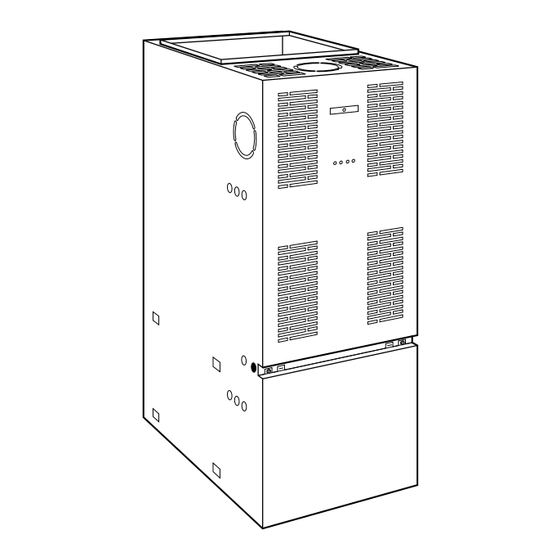
Fig. 1-58CMA Multipoise Oil Furnace
SAFETY CONSIDERATIONS
FOR YOUR SAFETY
Pg 1
1-98
58CMA
Multipoise
Oil Furnace
A97247
Replaces: 58CMA-1SI
Advertisement
Table of Contents

Related Manuals for Carrier 58CMA


Summary of Contents for Carrier 58CMA
-
Page 1: Table Of Contents
DUCT WORK RECOMMENDATIONS........5 VENTING ..................5 Vent System Inspection............5-6 Masonry Chimneys ..............6 Factory-Built Chimneys............6 OIL BURNER ................6 A97247 OIL CONNECTIONS ..............6 Fig. 1—58CMA Multipoise Oil Furnace BAROMETRIC DRAFT CONTROL ...........6 ELECTRICAL CONNECTIONS..........6-9 SAFETY CONSIDERATIONS 115-v Wiring................6 24-v Wiring................9 Accessories................9 FOR YOUR SAFETY Wiring Diagram.............. -
Page 2: Dimensional Drawing
TOP KNOCK-OUT FOR J DIAM VENT 20″ 19″ 3″ KNOCK-OUT BOTH SIDES 19″ FOR J DIAM VENT PULL VENT CONN OIL INLET (BOTH SIDES) 2″ ELECTRICAL CONNECTIONS (BOTH SIDES) .88 DIAM TYP 20″ A98037 DIMENSIONS (IN.) UNIT SIZE 105-12 48-3/4 30-1/4 16-5/8 1-1/2... -
Page 3: Minimum Clearance To Combustibles
1 in. → The model 58CMA Furnace is available in two sizes. Each size to 2 in. thick. unit is capable of 3 heat/airflow combinations by a simple nozzle →... -
Page 4: Air For Combustion And Ventilation
AIR FOR COMBUSTION AND VENTILATION For Example: →Minimum Floor Area for Unconfined Space 58CMA FURNACE MINIMUM SQ FT WITH Installation of this furnace in an area where it will receive INPUT BTUH 7-1/2 FT CEILING contaminated combustion air must be avoided. Such contami-... -
Page 5: Ductwork Recommendations
When supply ducts carry air circulated by furnace to areas outside spaces containing furnace, return air MUST also be FREE AREA PER handled by a duct sealed to furnace casing and terminating 58CMA FURNACE OPENING INPUT BTUH outside space containing furnace. Incorrect ductwork termi- (SQ IN.) -
Page 6: Masonry Chimneys
→Table 2—Electrical Data OPERATING VOLTS— UNIT MAX WIRE MAX FUSE OR VOLTAGE RANGE HERTZ— UNIT WIRE SIZE LENGTH (FT)† CKT BKR AMPS‡ PHASE AMPS GAGE Maximum* Minimum* 105-12 115—60—1 12.2 120-20 115—60—1 15.7 * Permissible limits of voltage range at which unit will operate satisfactorily. †... -
Page 9: 24-V Wiring
Step 2—24-v Wiring 6. RESET on primary control is pushed down. → Instructions for wiring thermostat (field supplied) are packed in 7. Flame observation door and 2 cleanout access doors located at thermostat box. Make thermostat connections as shown in Fig. 3 or front of unit are closed. -
Page 10: Fan Adjustment Check
5. The CO and stack temperature instruments enable you to obtain data required to determine thermal efficiency of fur- When operating furnace in heating mode, static pressure and nace. temperature rise (supply-air temperature minus return-air 6. An oil filter should be installed as close to burner as possible temperature) must be within those limits specified on rating with ALL oil burners and is essential on lower firing rate plate. -
Page 11: Maintenance
→Table 7—Airflow Data (CFM) EXTERNAL STATIC PRESSURE IN. WC UNIT BLOWER SIZE SPEED High 1425 1350 1305 1250 1170 1030 Med-High 1130 1045 1000 105-12 Med-Low High 2080 2041 1965 1864 1702 1576 1474 1336 Med-High 1892 1859 1770 1675 1550 1449 1330... -
Page 12: Blower Removal
[ ] Classroom Service Training A94328 Copyright 1998 CARRIER Corp. • 7310 W. Morris St. • Indianapolis, IN 46231 58cma2si Manufacturer reserves the right to discontinue, or change at any time, specifications or designs without notice and without incurring obligations.
Need help?
Do you have a question about the 58CMA and is the answer not in the manual?
Questions and answers