
Related Manuals for Pfaff 5625-657/01


Summary of Contents for Pfaff 5625-657/01
- Page 1 5625 -657/01 -657/01 INSTRUCTION MANUAL This instruction manual applies to machines from the following serial numbers onwards: # 2 731 762 296-12-18 933/002 Betriebsanleitung engl. 09.09...
- Page 2 This instruction manual applies to all versions and subclasses listed under "Specifi cations". Reprinting, copying or translation of PFAFF instruction manuals, whether in whole or in part, is not permitted without our prior permission and not without written indication of the source.
-
Page 3: Table Of Contents
Explanation of symbols ..................... 13 Controls ..........................14 Adjusting the stitch length ....................14 Adjusting the top feed stroke on the PFAFF 5625-657/01 ........... 14 Adjusting the top feed stroke on the PFAFF 5625-657/02 ........... 15 Lifting the presser foot......................15 Key for fi... - Page 4 Lifting motion of the top feed dog ..................43 .04.21 Clearance between the presser foot and the needle plate on the PFAFF 5625-657/01 ... 44 .04.22 Clearance between the presser foot and the needle plate on the PFAFF 5625-657/02 ...45 .04.23...
-
Page 5: Safety
Safety Safety Regulations This machine is constructed in accordance with the European regulations indicated in the conformity and manufacturer‘s declarations. In addition to this instruction manual, please also observe all generally accepted, statutory and other legal requirements, including those of the user‘s country, and the applicable pol-lu- tion control regulations! The valid regulations of the regional social insurance society for occupational accidents or other supervisory authorities are to be strictly adhered to! -
Page 6: Safety Symbols
The user must ensure that none of the safety devices are removed nor put out of work- ing order. ● The user must ensure that only authorized persons operate and work on the machine. For further information please refer to your PFAFF agency. -
Page 7: Notes For Operating And Technical Staff
Safety Notes for operating and technical staff Operating staff .05.01 Operating staff are the persons responsible for setting up, operating and cleaning the mach- ine and for removing any disturbances in the sewing area. The operating staff are obliged to observe the following points, and must: ●... -
Page 8: Danger Warnings
Safety Danger warnings A working area of 1 m must be kept free both in front of and behind the machine, so that easy access is possible at all times. Never put your hands in the sewing area during sewing! Danger of injury by the needle! While setting or adjusting the machine do not leave any objects on the table nor in the needle plate area! Objects may be trapped or slung out of the machine! -
Page 9: Proper Use
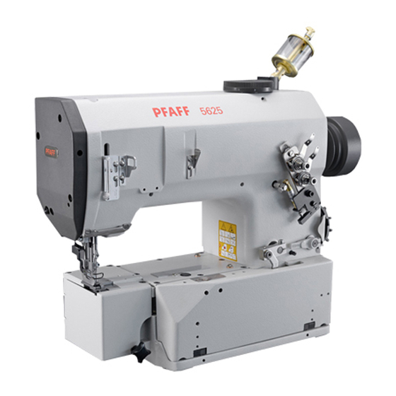
Proper use Proper use The PFAFF 5625-657/01 is a single needle double chain stitch specialist sewing machine with bottom feed, top feed and needle feed as well as pneumatic foot lift and tension release. Stroke adjustable by dial. The PFAFF 5625-657/02 is a single needle double chain stitch specialist sewing machine with bottom feed, top feed and needle feed as well as mechanical foot lift and tension release. -
Page 10: Specifi Cations
Specifi cations Specifi cations ▲ Stitch type: ......................401 (chainstitch) Version: ........................... C N8,5 Needle size: ........................ 150 - 180 Needle system: ......................... 62-59 Max. thread size: ......................... 11/3 (Synthetic or comparable sizes of other thread types) Effective balance wheel Ø: ....................80mm Presser foot clearance: .................... -
Page 11: Disposal Of Machine
Disposal of Machine Disposal of Machine ● Proper disposal of the machine is the responsibility of the customer. ● The materials used for the machine are steel, aluminium, brass and various plastic mat- erials. The electrical equipment comprises plastic materials and copper. ●... -
Page 12: Transportation, Packing And Storage
Transportation, packing and storage Transportation, packing and storage Transportation to customer‘s premises The machines are delivered completely packed. Transportation inside the customer‘s premises The manufacturer cannot be made liable for transportation inside the customer‘s premises nor to other operating locations. It must be ensured that the machines are only transported in an upright position. -
Page 13: Explanation Of Symbols
Explanation of symbols Explanation of symbols In this instruction manual, work to be carried out or important information is accentuated by symbols. These symbols have the following meanings: Note, information Cleaning, care Lubrication Maintenance, repairs, adjustment, service work (only to be carried out by technical staff) -
Page 14: Controls
1, the required stitch length can be set by turning adjustment wheel 2. Fig. 7 - 01 Adjusting the top feed stroke on the PFAFF 5625-657/01 ● The top feed stroke can be set by turning adjustment wheel 1. The maximum top feed stroke is limited by the manufacturer. -
Page 15: Adjusting The Top Feed Stroke On The Pfaff 5625-657/02
Controls Adjusting the top feed stroke on the PFAFF 5625-657/02 Switch off the machine! Danger of injury due to uninten- tional starting of the machine! ● Open cover on the rear side of the machine, loosen nut 1 and adjust lever 2 accordingly Fig. -
Page 16: Key For Fi Xing The Presser Foot
Controls Key for fi xing the presser foot ● The presser foot can be fi xed by raising it, then pressing key 1 and lowering the presser foot. ● To release it raise the presser foot. Fig. 7 - 05 Further control elements are described in the system service manual. -
Page 17: Installation And Commissioning
Installation and commissioning Installation and commissioning The machine must only be installed and commissioned by qualifi ed personnel! It is imperative that all relevant safety regulations are observed! Installation ● Suitable connections for electricity must be available at the machine’s location. ●... -
Page 18: Setting Up
Setting up Setting up All regulations and instructions in this service manual must be observed. Special attention must be paid to all safety regulations! All setting up work is only to be carried out by appropriately trained personnel. For all setting up work the machines must be disconnected from the mains by operating the main switch or by pulling out the plug. -
Page 19: Threading The Machine / Adjusting The Thread Tensions
Setting up Threading the machine / adjusting the thread tensions 62-023 Fig. 9 - 02 Switch off the machine! Danger of injury if the machine is started accidentally! ● Thread the needle thread as shown in Fig. 9-02. ● Adjust the needle thread tension by turning milled screw ●... -
Page 20: Care And Maintenance
Care and Maintenance Care and Maintenance Servicing and maintenance intervals Clean the looper compartment ....daily, several times when in continuous operation Clean the entire machine ..................once a week Check the gear oil level ................daily before use Check the oil level in the oil tank for the needle head parts......daily before use The maintenance intervals apply to an average machine running time for a single shift. -
Page 21: Checking The Oil Level / Fi Lling In Oil
2 and fi ll in oil until an air bubble is visible. ● Tighten screw 2 again. Only use oil with a mean viscosity of 22.0 mm²/s at 40ºC and a density of 0.865 g/cm³ at 15ºC. We recommend PFAFF sewing machine oil, part number 280-1-120 144. -
Page 22: Ölstand Des Ölbehälters Für Die Kopfteile Kontrollieren / Auffüllen
Before starting the machine open valve Only use oil with a mean viscosity of 22.0 mm²/s at 40ºC and a density of 0.865 g/cm³ at 15ºC. We recommend PFAFF sewing machine oil, part number 280-1-120 144. During long stop periods close valve 3. -
Page 23: Adjustment
Adjustment Adjustment The illustrations in this chapter show a PFAFF 5625-657/01 with pneumatic sewing foot lift.The PFAFF 5625-657/02 differs minimally in some respects from the illustrations shown. Notes on adjustment All following adjustments are based on a fully assembled machine and may only be carried out by expert staff trained for this purpose. -
Page 24: Adjusting The Basic Machine
Adjustment Adjusting the basic machine Needle height .04.01 (preliminary adjustment) Requirement When the needle bar is positioned at t.d.c., there should be a distance of approx. 11 mm between the needle point and the needle plate. 11 mm 62-024 Fig. 11 - 01 ●... -
Page 25: Driving Eccentric Of The Looper (Pre-Adjust)
Adjustment Driving eccentric of the looper .04.02 (Pre-adjust) Requirement When the needle bar is positioned at b.d.c., the round side of adjustment pin 1 (part no. 61-111 643-55) should lock into groove 5. Fig. 11 - 02 ● Insert adjustment pin 1 in hole 2. -
Page 26: Feed Lifting Eccentric
Adjustment Feed lifting eccentric .04.03 Requirement When the needle bar is positioned at b.d.c., slot 3 should be vertically above shaft 4. Fig. 11 - 03 ● Turn eccentric 1 (screws 2) in accordance with the requirement. -
Page 27: Driving Eccentric Of The Spreader
Adjustment Driving eccentric of the spreader .04.04 Requirement When the needle bar is positioned at b.d.c., slot 5 of eccentric 1 should be vertically above shaft 3. Spreader holder 4 should move a distance of 6 mm. 62-026 62-027 Fig. 11 - 04 ●... -
Page 28: Feed Driving Eccentric And Drive To Needle Bar Frame
Adjustment Feed driving eccentric and drive to needle bar frame .04.05 Requirement When the needle bar is positioned at b.d.c. Slot 7 of eccentric 1 should be vertically above shaft 5 and Crank 3 should be positioned vertical to shaft 6. Fig. -
Page 29: Positioning The Feed Dog
Adjustment Positioning the feed dog .04.06 Requirement When the maximum stitch length is set, the feed dog 4 should move laterally and lengthwise in the centre of the needle plate cut-out. 62-068 Fig. 11 - 06 ● Align device 1 (screws 2 and 3) in accordance with the requirement. -
Page 30: Feed Dog Height
Adjustment Feed dog height .04.07 Requirement When the needle bar is positioned at b.d.c. and with the maximum stitch length set, the front teeth of the feed dog 4 should be 1.1 mm above the needle plate. 62-029 Fig. 11 - 07 ●... -
Page 31: Position Of The Needle To The Needle Hole
Adjustment Position of the needle to the needle hole .04.08 Requirement Crosswise to the sewing direction, the needle should penetrate in the centre of the needle hole. When the needle bar is positioned at b.d.c., there should be a distance of 0.8 mm Between the needle and the front edge of the needle hole. -
Page 32: Position Of The Looper Crosswise To The Sewing Direction
Adjustment Position of the looper crosswise to the sewing direction .04.09 Requirement When its point is positioned in the centre of the needle, looper 1 Should be parallel to the needle plate cut-out and There should be a distance of 0.1 mm between the looper point and the needle. -
Page 33: Position Of The Looper In The Direction Of Sewing/Re-Adjusting The Looper Eccentric
Adjustment Position of the looper in the direction of sewing/re-adjusting the looper eccentric .04.10 Requirement When the needle bar is positioned 6.0 mm after b.d.c. and the stitch length is set at 8.5 mm, the looper point should be centred to the needle. 62-031 Fig. -
Page 34: Readjusting The Needle Height
Adjustment Readjusting the needle height .04.11 Requirement When the stitch length is set at 8.5 mm and the looper point approaching from the rear is in alignment with the front side of the needle, the bottom edge of the looper should be 1.0 - 1.2 mm above the eye of the needle. -
Page 35: Position Of The Spreader In The Direction Of Sewing
Adjustment Position of the spreader in the direction of sewing .04.12 Requirement The spreader tip should be inclined approx. 45° down and be 11 mm away from the spreader holder. When the stitch length is adjusted to maximum and the needle bar is in bottom dead centre position, the distance between the tip of spreader 1 and the needle should be 4 mm. -
Page 36: Position Of The Spreader Crosswise To The Direction Of Sewing
Adjustment Position of the spreader crosswise to the direction of sewing .04.13 Requirement The point of spreader 1 should have a side distance of 0.1 mm to the looper. The point of spreader 1 should be 0.1 mm above the back of the looper. 0,1 mm 62-034 62-033... -
Page 37: Needle Guard And Thread Loop Support
Adjustment Needle guard and thread loop support .04.14 Requirement When the looper point approaching from the rear is positioned at the centre of the needle Guard 1 should be touching the needle lightly and its lower edge should be positioned 0.5 mm above the needle tip. -
Page 38: Balancing Weightt
Adjustment Balancing weightt .04.15 Requirement When the needle bar is positioned at t.d.c., the greatest eccentricity of the balancing weight 1 should be at the bottom. Fig. 11 - 15 ● Adjust balancing weight 1 (screw 2) in accordance with the requirement. -
Page 39: Feed Difference
Adjustment Feed difference .04.16 Requirement With the maximum stitch length set, when the balance wheel is turned, the needle and bottom feed dog should carry out the same feed strokes. Fig. 11 - 16 ● Adjust connecting rod 1 (nut 2) in accordance with the requirement. ●... -
Page 40: Top Feed Stroke On The Pfaff 5625-657/01
Adjustment Top feed stroke on the PFAFF 5625-657/01 .04.17 Requirement When adjustment wheel 1 is set at position "5", the top feed dog 10 and presser foot 11 should both rise 5.0 mm. The standard stroke should be limited to 5 mm. -
Page 41: Top Feed Stroke On The Pfaff 5625-657/02
Adjustment Top feed stroke on the PFAFF 5625-657/02 .04.18 Requirement With the maximum feed stroke set, top feed dog 5 and presser foot 6 should each rise 5.0 mm. 62-014 62-015 Fig. 11 - 18 ● Remove the bottom feed dog and the needle. -
Page 42: Limiting The Top Feed Stroke (Only On The Pfaff 5625-657/01)
Adjustment Limiting the top feed stroke .04.19 (only on the PFAFF 5625-657/01) Requirement The maximum stroke of the top feed is set according to customer specifi cations (stan- dard setting: 5 mm) The minimum stroke should be at least 3 mm. -
Page 43: Lifting Motion Of The Top Feed Dog
Adjustment Lifting motion of the top feed dog .04.20 Requirement When the stroke is set at 3 mm, the top feed dog 3 should just have reached the needle plate when the needle, when approaching from above, is at the height of the needle plate. 62-039 Fig. -
Page 44: Clearance Between The Presser Foot And The Needle Plate On The Pfaff 5625-657/01
Adjustment Clearance between the presser foot and the needle plate .04.21 on the PFAFF 5625-657/01 Requirement When presser foot 1 is raised, there should be a clearance of approx. 11 mm between presser foot 1 and the needle plate. 11 mm 62-013 Fig. -
Page 45: Clearance Between The Presser Foot And The Needle Plate On The Pfaff 5625-657/02
Adjustment Clearance between the presser foot and the needle plate .04.22 on the PFAFF 5625-657/02 Requirement When presser foot 7 is raised the hand lever 4 should be parallel to the needle thread tension unit 5, the tip of crank 8 and bar 9 should be aligned and there should be a clearance of approx. -
Page 46: Needle Thread Tension Release (Only On The Pfaff 5625-657/01)
Adjustment Needle thread tension release .04.23 (only on the PFAFF 5625-657/01) Requirement When the presser foot is raised, tension disks 3 should be apart. Fig. 11 - 23 ● Raise the presser foot with the hand lever. ● Turn adjustment ring... -
Page 47: Needle Thread Regulator And Take-Up Lever Guard
Adjustment Needle thread regulator and take-up lever guard .04.24 Requirement When the needle bar is at b.d.c., there should be a clearance of 1 mm between thread take-up lever 8 and take-up lever guard 1. The thread take-up lever 8 should be centred to the take-up lever guard 1 as seen from the side. -
Page 48: Looper Thread Regulator
Adjustment Looper thread regulator .04.25 Requirement When the maximum stitch length is set, thread puller 1, at the top of its stroke, should have a clearance of 28 mm to the top edge of the bedplate . The eyes of thread puller 3 should be in alignment with the eyes of thread puller 1. -
Page 49: Limiting The Stitch Length
Adjustment Limiting the stitch length .04.26 Requirement For the required maximum stitch length, stop lug 1 should be touching stop 3. Fig. 11 - 26 ● Adjust stop lug 1 (screws 2) in accordance with the requirement. - Page 50 PFAFF Industriesysteme und Maschinen AG Hans-Geiger-Str. 12 - IG Nord D-67661 Kaiserslautern Phone: +49 - 6301 3205 - 0 Fax: +49 - 6301 3205 1386 E-mail: info@pfaff-industrial.com Hotlines: Technical service: +49 - 175/2243-101 Application consultance: +49 - 175/2243-102 Spare-parts hotline:...
Need help?
Do you have a question about the 5625-657/01 and is the answer not in the manual?
Questions and answers