Toshiba RAS-M10PKVP-E Service Manual
Split type, indoor & outdoor unit
Hide thumbs
Also See for RAS-M10PKVP-E:
- Service manual (152 pages) ,
- Service manual (5 pages) ,
- Service manual (135 pages)

Subscribe to Our Youtube Channel
Related Manuals for Toshiba RAS-M10PKVP-E


Summary of Contents for Toshiba RAS-M10PKVP-E
-
Page 1: Service Manual
FILE NO. A010-024 SERVICE MANUAL AIR-CONDITIONER SPLIT TYPE <Heat Pump Type> RAS-M10PKVP-E RAS-M13PKVP-E RAS-M16PKVP-E RAS-M18UAV-E R410A PRINTED IN JAPAN, Mar., 2011... -
Page 2: Table Of Contents
CONTENTS SAFETY PRECAUTIONS ................ 3 SPECIFICATIONS ..................5 REFRIGERANT R410A ................9 CONSTRUCTION VIEWS ..............17 WIRING DIAGRAM ................19 SPECIFICATIONS OF ELECTRICAL PARTS ........21 REFRIGERANT CYCLE DIAGRAM ............22 CONTROL BLOCK DIAGRAM .............. 24 OPERATION DESCRIPTION ..............26 INSTALLATION PROCEDURE .............. -
Page 3: Safety Precautions
SAFETY PRECAUTIONS For general public use Power supply cord of outdoor unit shall be more than 1.5 mm ² (H07RN-F or 245IEC66) polychloroprene sheathed fl exible cord. • Read this “SAFETY PRECAUTIONS” carefully before servicing. • The precautions described below include the important items regarding safety. Observe them without fail. •... - Page 4 • DO NOT INSTALL NEAR CONCENTRATIONS OF COMBUSTIBLE GAS OR GAS VAPORS. FAILURE TO FOLLOW THIS INSTRUCTION CAN RESULT IN FIRE OR EXPLOSION. • TO PREVENT THE INDOOR UNIT FROM OVERHEATING AND CAUSING A FIRE HAZARD, PLACE THE UNIT WELL AWAY (MORE THAN 2 M) FROM HEAT SOURCES SUCH AS RADIATORS, HEAT RESISTORS, FURNACE, STOVES, ETC.
-
Page 5: Specifications
A 2-room connection must always be used for the indoor units (you must connect two indoor units). With the RAS-M18UAV-E outdoor unit model, the 16 + 16 combination is not an option. The contents noted in this service manual limit the indoor units to the RAS-M10PKVP-E, RAS-M13PKVP-E, RAS-M16PKVP-E. -
Page 6: Heat Pump Models
2-1. Specifi cations <Heat Pump Models> RAS-M10PKVP-E, RAS-M13PKVP-E, RAS-M16PKVP-E / RAS-M18UAV-E Indoor RAS-M10PKVP-E, RAS-M13PKVP-E, RAS-M16PKVP-E Unit model Outdoor RAS-M18UAV-E Cooling capacity (kW) Cooling capacity range (kW) 1.4 – 6.2 Heating capacity (kW) Heating capacity range (kW) 0.9 – 8.3 Power supply 220–240 V –... - Page 7 2-2. Performance Specifi cations Combinations of Indoor Unit <Cooling> RAS-M18UAV-E Operating indoor unit Unit capacity (kW) Operation Volts Operation Capacity Running current Power Consumption mode status — — 2.0 (1.1 to 3.0) 2.40 (1.43 to 3.83) 460 (220 to 800) —...
-
Page 8: Operation Characteristic Curve
2-2-1 Operation Characteristic Curve RAS-M18UAV-E <Cooling> <Heating> • Conditions Indoor : DB 27˚C/WB 19˚C Outdoor : DB 35˚C Air flow : High Pipe length : 7.5m × 2 2 units operating 230V • Conditions Indoor : DB 20˚C Outdoor : DB 7˚C/WB 6˚C Air flow : High Pipe length : 7.5m ×... -
Page 9: Refrigerant R410A
REFRIGERANT R410A This air conditioner adopts the new refrigerant HFC 6. When an air conditioning system charged with a (R410A) which does not damage the ozone layer. large volume of refrigerant is installed in a small room, it is necessary to exercise care so that, The working pressure of the new refrigerant R410A even when refrigerant leaks, its concentration is 1.6 times higher than conventional refrigerant... - Page 10 Table 3-2-1 Thicknesses of annealed copper pipes Thickness (mm) Nominal diameter Outer diameter (mm) R410A 6.35 0.80 0.80 9.52 0.80 0.80 12.70 0.80 0.80 15.88 1.00 1.00 2. Joints For copper pipes, fl are joints or socket joints are used. Prior to use, be sure to remove all contaminants. a) Flare Joints Flare joints used to connect the copper pipes cannot be used for pipings whose outer diameter exceeds 20 mm.
- Page 11 d) Flare Processing Make certain that a clamp bar and copper ØD ØD pipe have been cleaned. By means of the clamp bar, perform the fl are processing correctly. Use either a fl are tool for R410A or conventional fl are tool. Flare processing dimensions differ according to the type of fl...
- Page 12 Table 3-2-6 Flare and fl are nut dimensions for R22 Dimension (mm) Nominal Outer diameter Thickness Flare nut width diameter (mm) (mm) (mm) 6.35 9.52 13.0 13.5 12.70 16.2 16.0 12.9 15.88 19.7 19.0 16.0 19.05 23.3 24.0 19.2 Fig. 3-2-2 Relations between flare nut and flare seal surface 2.
-
Page 13: Required Tools
3-3.Tools 3-3-1. Required Tools The service port diameter of packed valve of the outdoor unit in the air-water heat pump using R410A is changed to prevent mixing of other refrigerant. To reinforce the pressure-resisting strength, fl are processing dimensions and opposite side dimension of fl are nut (For Ø12.7 copper pipe) of the refrigerant piping are lengthened. -
Page 14: Recharging Of Refrigerant
3-4. Recharging of Refrigerant When it is necessary to recharge refrigerant, charge the specifi ed amount of new refrigerant according to the following steps. Recover the refrigerant, and check no refrigerant remains in the equipment. When the compound gauge’s pointer has indicated –0.1 Mpa (–76 cmHg), place the handle Low in the fully closed position, and turn off the vacuum pump’s power switch. -
Page 15: Brazing Of Pipes
1. Be sure to make setting so that liquid can be charged. 2. When using a cylinder equipped with a siphon, liquid can be charged without turning it upside down. It is necessary for charging refrigerant under condition of liquid because R410A is mixed type of refrigerant. Accordingly, when charging refrigerant from the refrigerant cylinder to the equipment, charge it turning the cylinder upside down if cylinder is not equipped with siphon. - Page 16 2. Characteristics required for fl ux 3-5-3. Brazing • Activated temperature of fl ux coincides with the As brazing work requires sophisticated techniques, brazing temperature. experiences based upon a theoretical knowledge, it • Due to a wide effective temperature range, fl ux must be performed by a person qualifi...
-
Page 17: Construction Views
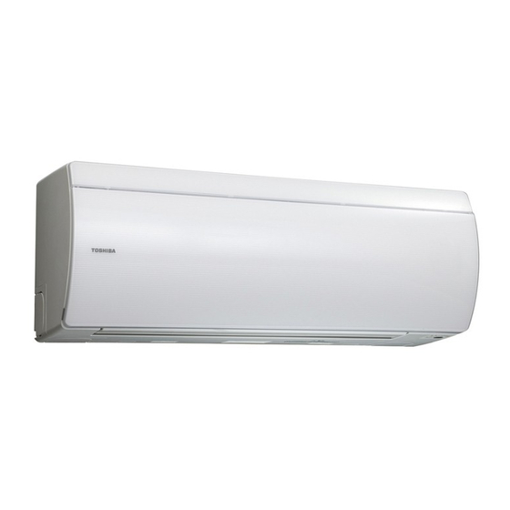
CONSTRUCTION VIEWS 4-1. Indoor Unit RAS-M10PKVP-E, RAS-M13PKVP-E, RAS-M16PKVP-E (At the time of operation) 296.2 Moving panel Plasma ion charger Front panel (At the time of a stop) Piping port from Air filter Piping port from left/right sides left/right sides Guard wire... - Page 18 4-2. Outdoor Unit RAS-M18UAV-E (Heat pump models) – 18 –...
-
Page 19: Wiring Diagram
WIRING DIAGRAM 5-1. Indoor Unit RAS-M10PKVP-E, RAS-M13PKVP-E, RAS-M16PKVP-E Air purifier electrode 3 2 1 Indoor terminal block Power supply Micro SW Sheet metal GRN&YEL CN501 CN03 CN01 CN21 CN401 CN382 (WHI) (RED) DC5V (TC) Power supply DC12V circuit DC29V CN603... - Page 20 5-2. Outdoor Unit RAS-M18UAV-E (Heat pump models) – 20 –...
-
Page 21: Specifications Of Electrical Parts
SPECIFICATIONS OF ELECTRICAL PARTS 6-1. Indoor Unit RAS-M10PKVP-E, RAS-M13PKVP-E, RAS-M16PKVP-E Parts name Type Specifi cations Fan motor (for indoor unit) ICF-340-30-4 DC 280–340 V, 30 W Room temp. sensor (TA-sensor) ( – ) 10 kΩ at 25°C Heat exchanger temp. sensor (TC-sensor) ( –... -
Page 22: Refrigerant Cycle Diagram
REFRIGERANT CYCLE DIAGRAM 7-1. Refrigerant Cycle Diagram RAS-M10PKVP-E, RAS-M13PKVP-E, RAS-M16PKVP-E RAS-M18UAV-E Temp. measurement INDOOR UNIT Indoor heat To B room To B room exchanger Indoor fan Per 1 unit Max. : 20m Deoxidized copper pipe min : 2m Pressure measurement... -
Page 23: Operation Data
7-2. Operation Data <Cooling> RAS-M18UAV-E Temperature Operating Standard Heat exchanger No. of Compresser Indoor Outdoor condition (°C) combination (unit) pressure pipe temp operating revolution units (rps) Indoor Outdoor P (MPa) T1(°C) T2(°C) — 1.0 to 1.2 12 to 14 35 to 37 High 700rpm —... -
Page 24: Control Block Diagram
CONTROL BLOCK DIAGRAM 8-1. Indoor Unit RAS-M10PKVP-E, RAS-M13PKVP-E, RAS-M16PKVP-E Indoor Unit Control Unit M.C.U. Humidity sensor Louver Functions Motor Heat Exchanger Sensor (Tcj) • Cold Draft Preventing Function Louver Motor • 3-minute Delay at Restart for Compressor Heat Exchanger Sensor (Tc) Drive Control •... - Page 25 8-2. Outdoor Unit (Inverter Assembly) RAS-M18UAV-E (Heat pump models) – 25 –...
-
Page 26: Operation Description
OPERATION DESCRIPTION 9-1. Outline of Air Conditioner Control • Detection of inverter input current and current release operation This air conditioner is a capacity-variable type air • Over-current detection and prevention operation conditioner, which uses DC motor for the indoor fan to IGBT module (Compressor stop function) motor and the outdoor fan motor. - Page 27 9-2. Operation Description 9-2. 1. Basic operation ..........................28 1. Operation control ........................28 2. Operating mode selection when performing 2-room operation ..........29 3. Cooling/Heating operation ..................... 29 4. AUTO operation ........................30 5. DRY operation ........................30 2. Indoor fan motor control ......................31 <In cooling operation>...
-
Page 28: Basic Operation
Item Operation fl ow and applicable data, etc. Description 1. Operation control 1. Basic operation Receiving the user’s operation condition setup, the operation statuses of indoor/outdoor units are controlled. 1) The operation conditions are selected by the remote controller as shown in the below. 2) A signal is sent by ON button of the remote controller. -
Page 29: Operating Mode Selection When Performing 2-Room Operation
Item Operation fl ow and applicable data, etc. Description 2. Operating mode selection when performing 2-room operation 1. Basic operation 1) The outdoor unit operating mode conforms to the instructions of the indoor unit that was pushed fi rst. (Continued) 2) When combined operation consisting of cooling (dry) and heating, fan (air purifi... -
Page 30: Auto Operation
Item Operation fl ow and applicable data, etc. Description 4. AUTO operation 1. Basic 1) Detects the room temperature operation (Ta) when the operation started. Selection of operation mode (Continued) 2) Selects an operation mode from As shown in the following fi gure, the operation starts by Ta in the left fi... -
Page 31: Indoor Fan Motor Control
*8 : Fan speed = (H –L+) × 1/4 + L+ controlled from W2 (20 seconds) (Linear approximation from M+ and L) to 0 rpm (40 seconds). (Table 1) Indoor fan air flow rate (Cooling, Dry) RAS-M10PKVP-E RAS-M13PKVP-E RAS-M16PKVP-E Fan speed level Fan speed Air flow rate... -
Page 32: In Heating Operation> (Heat Pump Model)
Item Operation fl ow and applicable data, etc. Description <In heating operation> (Heat pump model) 2. Indoor fan 1) When setting the fan speed motor control to L, L+, M, M+ or H on the (This operation controls the fan speed at indoor unit side.) (Continued) remote controller, the operation The indoor fan (cross fl... - Page 33 • When 25 minutes or more passed after operation start FAN Manual • Room temp. < Set temp. –4°C • Room temp. Set temp. –3.5°C (Table 2) Indoor fan air flow rate (Heating) RAS-M10PKVP-E RAS-M13PKVP-E RAS-M16PKVP-E Fan speed level Fan speed Air flow rate Fan speed Air flow rate...
-
Page 34: Outdoor Fan Motor Control
Item Operation fl ow and applicable data, etc. Description 3. Outdoor fan The blowing air volume at the outdoor unit side is controlled. 1) The operation command sent motor control Receiving the operation command from the controller of indoor from the remote controller is unit, the controller of outdoor unit controls fan speed. -
Page 35: Capacity Control
Item Operation fl ow and applicable data, etc. Description 4. Capacity 1) Two indoor units from A and B determine the respective instruction revolutions from the difference control between the remote controller setting temperature (Ts) and the indoor temperature (Ta), and transmit this to the outdoor unit. -
Page 36: Release Protective Control By Temperature Of Indoor Heat Exchanger
Item Operation fl ow and applicable data, etc. Description <In cooling/dry operation> 6. Release protective control 1) When temperature of the by temperature of indoor indoor heat exchanger drops (Prevent-freezing control for indoor heat exchanger) heat exchanger below 5°C, the compressor In cooling/dry operation, the sensor of indoor heat exchanger detects evaporation temperature and speed is reduced. -
Page 37: Winding/Coil Heating Control
Item Operation fl ow and applicable data, etc. Description 7. Winding/Coil When the outdoor temperature is low, the windings/coils Winding/Coil heating is performed when heating control are heated to ensure compressor reliability. the following conditions are met. Condition 1 : When the discharge sensor temperature Outdoor temperature To Winding/Coil... -
Page 38: Louver Control
Item Operation fl ow and applicable data, etc. Description 9. Louver control This function controls the air direction of the indoor unit. 1) Louver • The position is automatically controlled according to the operation mode (COOL/HEAT). position • The set louver position is stored in memory by the microcomputer, and the louver returns to the stored position when the next operation is performed. -
Page 39: Sleep Mode Operation
Item Operation fl ow and applicable data, etc. Description 10. SLEEP When pushing [SLEEP MODE] button on the remote controller, a MODE quiet and mild operation is performed by reducing the fan speed operation and the compressor speed. <Cooling operation> <Cooling operation>... -
Page 40: Temporary Operation
Item Operation fl ow and applicable data, etc. Description 11. Temporary Pushing [RESET] button starts the temporary 1) When pushing [RESET] button, the operation operation of [AUTO] operation. When keeping temporary [AUTO] operation starts. [RESET] button pushed for 10 seconds or more, the 2) When keeping [RESET] button pushed for 3 temporary [COOL] operation is performed. - Page 41 Item Operation fl ow and applicable data, etc. Description 12. Air purifying 2. Description control Error is determined to have occurred (Continued) (indicated by the PURE indicator (Orange) in the following two cases. 1) When the panel switch has been set Air purifying operation to OFF by the opening of the air inlet grill ,etc.
-
Page 42: Discharge Temperature Control
Item Operation fl ow and applicable data, etc. Description 1. Purpose 13. Discharge temperature This function detects error on the control refrigerating cycle or error on the compressor, and performs protective control. Td value Control operation 2. Operation Judges as an error and stops the compressor. •... -
Page 43: Clean Operation
Item Operation fl ow and applicable data, etc. Description 1. Purpose 15. Clean operation The clean operation is to minimize the growth of mold, bacteria etc. by running the fan and drying so as to keep the inside of the air conditioner clean. Unit now performing cooling or dry operation Clean operation When the cooling or dry operation shuts... -
Page 44: Clean Operation Cancel
Item Operation fl ow and applicable data, etc. Description Setting the clean operation cancel 16. Clean operation CAUTION cancel ∗ J231 will be near the MCU so take Add J231 of the wireless unit P.C. board assembly. steps to ensure that it will not be This cancels the auto restart function. -
Page 45: Select Switch On Remote Controller
Item Operation fl ow and applicable data, etc. Description 1. Purpose 17. Select switch on remote controller This operation is to operate only one indoor unit using one remote controller. 2. Description When operating one indoor unit in a Push the operation button situation where two indoor units have on the remote controller. -
Page 46: Set Temperature Correction
Item Operation fl ow and applicable data, etc. Description Indoor Control P.C. Board (Factory Default) 1. Purpose 18. Set temperature correction When the difference between the set temp. of the remote controller and the room temp. is wide due to the Jumper wire J804 installation condition, etc, the set temp. -
Page 47: Auto Restart Function
9-3. Auto Restart Function This indoor unit is equipped with an automatic restarting function which allows the unit to restart operating with the set operating conditions in the event of a power supply being accidentally shut down. The operation will resume without warning 3 minutes after power is restored. This function is not set to work when shipped from the factory. -
Page 48: Cancel The Auto Restart Function
9-3-2. Cancel the Auto Restart Function To cancel auto restart function, proceed as follows : Repeat the setting procedure : the unit receives the signal and beeps 3 times. The unit will be required to be turned on with the remote controller after the main power supply is turned off. •... -
Page 49: Remote Controller And Its Functions
9-4. Remote Controller and Its Functions 9-4-1. Parts Name of Remote Controller Auto louver button (SWING) Each time you push the SWING button, you can change the swing mode. (A receiving beep is heard.) (Vertical swing → Horizontal swing → Vertical and Horizontal swing →... -
Page 50: Name And Functions Of Indications On Remote Controller
9-4-2. Name and Functions of Indications on Remote Controller [Display] All indications, except for the clock time indicator, are displayed by pushing the button. Transmission mark (MEMORY) indicator This transmission mark ▲ indicates when the Flashes for 3 seconds when the MEMO button is remote controller transmits signals to the indoor pressed during operation. -
Page 51: Hi-Power Mode
9-5. Hi-POWER Mode When [Hi POWER] button is pushed while the indoor unit is in Auto, Cooling or Heating operation, Hi POWER mark is indicated on the display of the remote controller and the unit operates according to the present operation mode as described below. -
Page 52: Installation Procedure
INSTALLATION PROCEDURE 10-1. Safety Cautions The indoor unit shall be installed so that the top of the indoor unit is positioned For the rear left and left piping at least 2 m high. Also, avoid putting anything on the top of the indoor unit. Wall Hook 70 mm or more... -
Page 53: Optional Installation Parts
Refrigerant piping Liquid side Gas side Indoor unit name (Outer diameter) (Outer diameter) 1 ea. RAS-M10PKVP-E, RAS-M13PKVP-E 6.35 mm 9.52 mm RAS-M16PKVP-E 6.35 mm 12.7 mm Shield pipe (for extension drain hose) (polyethylene foam, 8 mm thick) 10-2-2. Accessory and Installation Parts Part No. -
Page 54: Installation/Servicing Tools
10-2-3. Installation/Servicing Tools Changes in the product and components In the case of an air conditioner using R410A, in order to prevent any other refrigerant from being charged accidentally, the service port diameter of the outdoor unit control valve (3-way valve) has been changed. (1/2 UNF 20 threads per inch) •... -
Page 55: Installation Place
10-3. Indoor Unit 10-3-2. Drilling and Mounting Installation Plate 10-3-1. Installation Place Drilling • A place which provides enough spaces around the When installing the refrigerant pipes from the rear. indoor unit as shown in the diagram. • A place where there are no obstacle near the air inlet and outlet. -
Page 56: Electrical Work
10-3-3. Electrical Work Mounting the installation plate directly on a wall 1. The supply voltage must be the same as the rated voltage of the air conditioner. 1. Securely fi t the installation plate onto the wall by screws with the upper and lower catches. 2. -
Page 57: Wiring Connection
10-3-4. Wiring Connection Connecting cable Termin l cov r Screw Wiring the connecting cable can be carried out Terminal block without removing the front panel. 1. Remove the air inlet grille. Open the air inlet grille upward and pull it toward Earth wire you. - Page 58 10-3-5. Piping and Drain Hose Installation 4. Attach the drain cap • Insert hexagonal wrench (4 mm). Piping and drain hose forming Since condensation results in machine trouble, make sure to insulate both the connecting pipes separately. (Use polyethylene foam as insulating material.) Rear right Rear left 4 mm...
- Page 59 Piping on the bottom right or the bottom left CAUTION • After making slits on the front panel with a knife or • Bind the auxiliary pipes (two) and connecting similar tool, cut them out with a pair of nippers or cable with facing tape tightly.
-
Page 60: Indoor Unit Installation
10-3-6. Indoor Unit Installation 10-3-7. Drainage 1. Pass the pipe through the hole in the wall, and 1. Run the drain hose at a downward sloped angle. hook the indoor unit on the installation plate at the upper hooks. NOTE: 2. - Page 61 10-4. Which Models Can Be Combined Table of models that can be used in combination Type Outdoor unit Combinations of indoor unit models that can be connected Heat pump RAS-M18UAV-E 07 + 07, 07 + 10, 07 + 13, 07 +16, 10 + 10, 10 + 13, 10 + 16, 13 + 13, 13+ 16 NOTE: A 1-room connection is not an option for the indoor units (you cannot connect only one indoor unit).
-
Page 62: Installation Of Outdoor Unit
10-5. Installation of Outdoor Unit • When doing installation work at ground level, it is usual to make wiring and pipe connections to the 10-5-1. Installation Location indoor units, fi rst, and then to make connections to the outdoor units. •... -
Page 63: Precautions About Installation In Regions With Snowfall And Cold Temperatures
Draining off the water from the outdoor unit Fixing the outdoor unit • If it is necessary to drain off the water from the • Secure the outdoor unit with the anchor bolts. outdoor unit, install two water-proofi ng rubber caps •... -
Page 64: Refrigerant Piping
10-5-2. Refrigerant piping Pipe Flare Nut Rigid Imperial How to remove the service valve cover (clutch (wing nut Outside Thickness type) type) Tighten torque diameter • Remove the three screws. R410A R410A tool tool Pull the service valve cover in the direction of the N•m kgf•m arrow, and remove it. -
Page 65: Air Purge
6. Check the gas leaks after connection. Air purge Undertake the steps described below in each of the Tighten torque two rooms. Service valve Valve stem cap Service port cap With respect to the preservation of the terrestrial N•m kgf•m N•m kgf•m environment, adopt “Vacuum pump”... -
Page 66: Adding Refrigerant
5. Any handling of the fl uorinated greenhouse gas Adding refrigerant in the product, such as when moving the product • No more refrigerant needs to be added if the total or recharging the gas, shall comply under (EC) pipe length is no more than 20 meters. Regulation No.842/2006 on certain fl... - Page 67 Insulating the pipes CAUTION • Insulate the pipes separately for the liquid side and In a pump-down operation, be sure to take the gas side. following steps. - Ensure that no air is allowed to enter inside the refrigeration cycle. - After having closed the two service valves, shut down the compressor, and then remove the refrigerant pipe.
- Page 68 Terminal block Wiring connection • The dashed lines show on-site wiring. 1 2 3 1 2 3 L N (Indoor/outdoor (Main circuit) connecting wires) Input power Remote controller Indoor unit Outdoor unit Earth Leakage breaker Fig. 10-5-14 Connecting Power cord •...
-
Page 69: Test Operation
10-5-5. Test operation • When performing the test operation during the winter months, proceed with the heating Miswiring (Mis-piping) check operation fi rst, and then perform the cooling operation. 1. Turn on the power breaker. (Cooling operation: Remote control 2. Set all the connected indoor units to COOL mode temperature setting of 17°C ) and check the operation. - Page 70 10-6. Test Operation 10-6-4. Select Switch on Remote Controller • If two indoor units are installed in the same room 10-6-1. Gas Leak Test or adjoining rooms, when the user tries to operate Check the fl are nut connections for gas leaks with a only one unit, both units may receive the same gas leak detector and/or soapy water.
- Page 71 10-7. Useful Functions 10-7-1. Self-Diagnosis by LED Indication • For this outdoor unit, by referring to the 5 LED (Red) indicator lights, self-diagnosis is possible. • LEDS (Red, D09 to D13) are located on the sub-control board underneath the inverter. LED indication Contents Indoor alarm code...
-
Page 72: How To Diagnose The Trouble
HOW TO DIAGNOSE THE TROUBLE The pulse motor circuits are mounted to both indoor and outdoor units. Therefore, diagnose troubles according to the trouble diagnosis procedure as described below. (Refer to the check points in servicing written on the wiring diagrams attached to the indoor/outdoor units.) Table 11-1 Troubleshooting Procedure Page... - Page 73 CAUTION A high voltage (equivalent to the supply voltage) is also energized to ground through the sensors, PMV and other low-voltage circuits. The sensor leads and other wires are covered with insulated tubes for protection. Nevertheless, care must be taken to ensure that these wires are not pinched. Take suffi...
- Page 74 11-1. First Confi rmation 11-1-3. Operation Which is not a Trouble (Program Operation) 11-1-1. Confi rmation of Power Supply For controlling the air conditioner, the program Confi rm that the power breaker operates (ON) operations are built in the microcomputer as normally.
-
Page 75: Primary Judgment
11-2. Primary Judgment To diagnose the troubles, use the following methods. 1) Judgment by fl ashing LED of indoor unit 2) Self-diagnosis by service check remote controller 3) Judgment of trouble by every symptom Firstly use the method (1) for diagnosis. Then, use the method (2) or (3) to diagnose the details of troubles. For any trouble occurred at the outdoor unit side, detailed diagnosis is possible by 5 serial LED (Red) on the control P.C. -
Page 76: Self-Diagnosis By Remote Controller (Check Code)
11-4. Self-Diagnosis by Remote Controller (Check Code) 1. If the lamps are indicated as shown B to E in Table 11-3-1, execute the self-diagnosis by the remote controller. 2. When the remote controller is set to the service mode, the indoor controller diagnoses the operation condition and indicates the information of the self-diagnosis on the display of the remote controller with the check codes. - Page 77 11-4-2. Check Code 1. After servicing, press the START/STOP button to return to the normal mode. 2. After servicing by the check code, turn off breaker of the power supply, and turn on breaker of the power supply again so that memory in the microcomputer returns the initial status. However, the check codes are not deleted even if the power supply is turned off because they are stored in the fi...
- Page 78 Block distinction Operation of diagnosis function Judgment and action Check Check Block Cause of operation conditioner Remarks code code status Outdoor Inverter over-current All off Displayed when Even if trying operation again, all P.C. board protective circuit error is detected. operations stop immediately.
-
Page 79: Judgment Of Trouble By Symptom
11-5. Judgment of Trouble by Symptom 11-5-1. Indoor Unit (Including Remote Controller) (1) Power of indoor unit does not turned on <Primary check> 1. Is the supply voltage normal? 2. Is the normal voltage provided to the outdoor unit? 3. Is the crossover cable connected properly? 4. - Page 80 (3) Only the indoor motor fan does not operate <Primary check> 1. Is it possible to detect the power supply voltage (AC220–240V) between a and b on the terminal block? 2. .Does the indoor fan motor operate in cooling operation? (In heating operation, the indoor fan motor does not operate for approximately 10 minutes after it is turned on, to prevent a cold air from blowing in.) Turn off power...
- Page 81 (4) Indoor fan motor automatically starts to rotate by turning on power supply <Cause> The IC is built in the indoor fan motor. Therefore the P.C. board is also mounted to inside of the motor. If the P.C. board is soldered imperfectly or the IC is defective, the fan motor may automatically rotate by turning on power supply.
- Page 82 (5) Troubleshooting for remote controller <Primary check> Check that A or B selected on the main unit is matched with A or B selected on the remote controller. The unit does not beep at all. Push the START/STOP button. Operation lamp on indoor unit is not indicated.
- Page 83 11-5-2. Wiring Failure (Interconnecting and Serial Signal Wire) (1) Outdoor unit does not operate 1) Is the voltage between b and c of the indoor terminal block varied? 2) Confi rm that transmission from indoor unit to outdoor unit is correctly performed based upon the following diagram.
- Page 84 11-6. Check Code 1C (Miswiring in indoor/outdoor units) and 1E <Check procedure> Disconnection of TGa sensor. Discharge temp. error, TGb sensor, P.M.V sensor error gas leakage (Check dode 02,1C) (Check code 03,1E) Miswiring in indoor/outdoor units, gas leakage, disconnection of TS/TC sensors (Check code 02, 1C) Operation...
- Page 85 11-7. Trouble Diagnosis by Outdoor LED For the outdoor unit, the self-diagnosis is possible by fi ve LEDs (Red). • LEDs (Red) (D09 to D13) are provided on the sub- control board under surface of the inverter, and as shown below, they are checked from the wiring port when removing the wiring cover.
-
Page 86: Troubleshooting
11-8. Troubleshooting 11-8-1. How to Check Whether the Air Purifi er is Good or Not Turn off the power breaker once, and turn on again after 10 seconds. Does the OPERATION indicator flash? To item “Power supply is not turned on” Turn off the power breaker and remove CN401 (Micro switch connector). -
Page 87: How To Diagnose Trouble In Outdoor Unit
11-9. How to Diagnose Trouble in Outdoor Unit 11-9-1. Summarized Inner Diagnosis of Inverter Assembly Table 11-9-1 Diagnosis/Process fl owchart Item Contents Summary Preparation Turn “OFF” the power supply Remove connector breaker, and remove 3P of compressor. connector which connects inverter and compressor. - Page 88 Diagnosis/Process fl owchart Item Contents Summary Check Check winding resistance between phases of compressor, and resistance between outdoor frames by using a tester. • Is not grounded. → OK if 10MΩ or more Replace control • Is not short-circuited board assembly. →...
- Page 89 (3) Check procedures Table 11-10-1 Procedure Check points Causes Turn off the power supply breaker Check whether or not the fuse (F01) Impulse voltage was applied or the and remove the P.C. board is blown. indoor fan motor short-circuited. assembly from electronic parts base.
- Page 90 11-10-2. P.C. Board Layout +12V IC801 DB01 T101 [1] Sensor characteristic table TD : Discharge temp. sensor TA : Room temp. sensor TC : Heat exchanger temp. sensor TO : Outdoor temp. sensor TE : Outdoor heat exchanger temp. sensor TS : Suction temp.
-
Page 91: Outdoor Unit
11-10-3. Indoor Unit (Other Parts) Part name Checking procedure Room temp. (TA) sensor Disconnect the connector and measure the resistance value with tester. Heat exchanger (TC) sensor (Normal temp.) Heat exchanger (TCj) sensor Temperature 10°C 20°C 25°C 30°C 40°C Sensor TA, TC, TCj (k ) 20.7 12.6... - Page 92 Part name Checking procedure Outdoor temperature sensor (TO), Disconnect the connector, and measure resistance value with the tester. discharge temperature sensor (Normal temperature) (TD), suction temperature sensor Temperature (TS), outdoor heat exchanger 10°C 20°C 25°C 30°C 40°C Sensor temperature sensor (TE), A TD (k ) room gas side temperature sensor (TGa), B room gas side...
-
Page 93: How To Simply Judge Whether Outdoor Fan Motor Is Good Or Bad
11-11. How to Simply Judge Whether Outdoor Fan Motor is Good or Bad 1. Symptom • Outdoor fan motor does not rotate. • Outdoor fan motor stops within several tens seconds though it started rotating. • Outdoor fan motor rotates or does not rotate according to the position where the fan stopped, etc. Remote controller check code “02 : Outdoor block, 1A : Outdoor fan drive system error”... -
Page 94: How To Replace The Main Parts
HOW TO REPLACE THE MAIN PARTS 12-1. Indoor Unit WARNING Since high voltages is applied to electrical parts, turn off the power without fail before starting replacement work. After repairs have been completed and the front panel and cabinet have been attached, perform test run and check for smoke, unusual sound, and other abnormalities. - Page 95 12-1-2. Fixing Frame Assembly 12-1-3. Electric Parts Cover Detached 1) Detach the two air fi lters. 1) Perform work of Detachment 12-1-1. Removing the Front Panel and Moving Panel. 2) Disconnect the plasma ion charger connector and the earth lead (black). (The earth lead is 2) Remove the screw beside the screw that secures connected to the heat exchanger with a screw.) the electric parts box assembly.
- Page 96 12-1-4. Microcomputer P.C. Board 12-1-5. Louver 1) Remove the electric parts cover screw. 1) Open the moving panel, and support it with the panel support. 2) Detach the metal electric parts cover. 2) Open the vertical air fl ow louver. 3) Disconnect the connectors from the P.C.
-
Page 97: Heat Exchanger
12-1-6. Heat Exchanger 12-1-7. Fan Motor 1) Perform work of Detachment 12-1-1. Removing 1) Perform work of Detachment 12-1-1. Removing the Front Panel and Moving Panel and 12-1-2. the Front Panel and Moving Panel and 12-1-3. Fixing Frame Assembly. Electric Parts Cover Detached. 2) Remove the pipe holder at the rear of the unit. - Page 98 12-1-8. Cross Flow Fan Keep 27mm distance between the support shaft at the rear centre of the unit and the 1) Perform work of Detachment 12-1-1. Removing the Front Panel and Moving Panel and 12-1-2. immediate right joint-section of the cross fl ow Fixing Frame Assembly.
- Page 99 12-2. Plasma Ion Charger 12-2-3. High-voltage Power Supply Unit and Discharger Unit 12-2-1. Common Procedure 1) Perform work of Detachment 12-1-1. Removing 1) Perform work of Detachment 12-1-1. Removing the Front Panel and Moving Panel. the Front Panel and Moving Panel for the 2) Disconnect the 4P connector on the high-voltage indoor unit.
- Page 100 12-3. Outdoor Unit Part name Procedure Remarks Common 1. Detachment procedure NOTE Upper cabinet Wear gloves for this job. Water proof cover Otherwise, you may injure your hands on the parts, etc. 1) Stop operation of the air conditioner, and turn off the main switch of the breaker for air conditioner.
- Page 101 Part name Procedure Remarks Front 1. Detachment cabinet Motor base 1) Perform step 1 in a. 2) Remove the fi xing screws (ST1TØ4 Inverter cover × 8L 2 pcs.) used to secure the front cabinet and inverter cover, the screws (ST1TØ4 ×8L 3 pcs.) used to secure the front cabinet at the bottom, the fi...
- Page 102 Part name Procedure Remarks Inverter 1) Perform work of item 1 in a. Inverter cover assembly P . C. board 2) Remove screw (ST1TØ4 × 8L 2 pcs.) of the (Soldered surface) upper part of the front cabinet. • If removing the inverter cover in this condition, P.C.
- Page 103 Part name Procedure Remarks Control 1. Disconnect the leads and connectors connected to board the other parts from the control board assembly. assembly 1) Leads CN701 • 3 leads (black, white, orange) connected to terminal block. CN300 • Lead connected to compressor : Disconnect the connector (3P).
- Page 104 Part name Procedure Remarks Side cabinet 1. Side cabinet (right) 1) Perform step 1 in b and all the steps in 2) Remove the fi xing screw (ST1TØ4 × 8L 5 pcs.) used for securing the side cabinet to the bottom plate and valve fi xing panel. 2.
- Page 105 Part name Procedure Remarks Compressor 1) Perform work of item 1 of a and b, c, d, 2) Extract refrigerant gas. 3) Remove the partition board. (ST1TØ4 × 8L 3 pcs.) Partition board 4) Remove the sound-insulation material. 5) Remove terminal cover of the compressor, and disconnect lead wire of the compressor and the comp.
- Page 106 Part name Procedure Remarks Electronic 1. Detachment expansion 1) Perform step 1 in b, all the steps in c and 1 in valve coil Coil 2) Remove the coil by pulling it up from the anti-turn lock electronic control valve body. 2.
- Page 107 Part name Procedure Remarks TE sensor (outdoor heat exchanging temperature sensor) • Attachment Arrow E With the sensor leads pointing in the direction shown in the fi gure, install the sensor onto the straight pipe part of the condenser output pipe. Detail D Detail C Detail C...
- Page 108 Outdoor unit Main P.C. board (MCC-5009) – 108 –...
- Page 109 Outdoor unit Sub P.C. board (MCC-5015-03) – 109 –...
-
Page 110: Exploded Views And Parts List
EXPLODED VIEWS AND PARTS LIST 13-1. Indoor Unit RAS-M10PKVP-E, RAS-M13PKVP-E, RAS-M16PKVP-E 221, 222 • The parts in the following parts list are conformed to RoHS. Therefore be sure to use the following parts for repairing and replacing. Location Location Part No. - Page 111 13-2. Microcomputer P.C. Board RAS-M10PKVP-E, RAS-M13PKVP-E, RAS-M16PKVP-E 417, 418, 419 • The parts in the following parts list are conformed to RoHS. Therefore be sure to use the following parts for repairing and replacing. Location Location Part No. Description Part No.
- Page 112 Compressor, DA130A1F-25F 43032441 Nipple, Drain 43043815 Condenser Ass’y 43089160 Cap, Waterproof 37546845 Valve, Packed, 6.35 4301L506 Mark, TOSHIBA, IMS 43046509 Valve, Packed, 9.52 43042485 Rubber, Cushion 43147196 Bonnet, 1/4 IN 43063321 Holder, Sensor, ø4, 8-9.52 (TD, 43047401 Bonnet, 3/8 IN...
- Page 113 13-4. P.C. Board Layout 701 Sensor, TE 702 Sensor, TS 703 Sensor, TO 704 Sensor, TGa (Ø4) 705 Sensor, TGb (Ø4) 708 Sensor, TD (Ø4) • The parts in the following parts list are conformed to RoHS. Therefore be sure to use the following parts for repairing and replacing. Location Location Part No.
- Page 114 This product is compliant with Directive 2002/95/EC, and cannot be disposed as unsorted municipal waste. Copyright © 1999 to 2009 TOSHIBA CARRIER CORPORATION, ALL Rights Reserved.
Need help?
Do you have a question about the RAS-M10PKVP-E and is the answer not in the manual?
Questions and answers