Advertisement
Quick Links
Advertisement

Related Manuals for Yale RH00529S


Summary of Contents for Yale RH00529S
- Page 1 RH00529S RH00538S DEC10.0101 READ AND SAVE THESE INSTRUCTIONS...
- Page 3 SAFETY NOTICE ..............LIST OF MATERIALS ............INSTALLATION Ducting Calculation Sheet ........Mounting Height & Clearance ........ Ducting Options ............Speci¿ cations ............... Electrical ................. Installing the Power Pack ........FEATURES & CONTROLS Controls ..............MAINTENANCE Cleaning and Installing Filters .......
- Page 4 READ AND SAVE THESE INSTRUCTIONS WARNING TO REDUCE THE RISK OF FIRE OR ELECTRIC SHOCK, DO NOT USE THIS FAN WITH ANY SOLID-STATE CONTROL DEVICE. WARNING TO REDUCE THE RISK OF FIRE ELECTRIC SHOCK, OR INJURY TO PERSONS, OBSERVE THE FOLLOWING: a.
- Page 5 15 or 20 ampere circuit breaker or time delay fuse. Wiring must be 2 wire with ground. Please also refer to Electrical Diagram on product. RH00529S - 720W, 6.1 Amps RH00538S - 790W, 6.7 Amps A cable locking connector (not supplied) might also be required by local codes. Check with local requirements, purchase...
- Page 6 MODELS: RH00529S and RH00538S PARTS SUPPLIED 2 - Decorative mesh ¿ lters (RH00538S Qty 3) 2 - Halogen light bulbs (RH00538S Qty 4) 1 - Dual internal blower (pre installed) ” 8 1 - Hardware package HARDWARE PACKAGE CONTENTS Suction Cup (1) M4 x 1”...
- Page 7 Equivalent number Equivalent number Duct pieces Duct pieces length x used T otal length x used T otal 3-1/ 4” x 10” 1 Ft. 6” Round 30 Ft. Rect., wall cap straight with damper 6” Round, 1 Ft. 6” Round, 30 Ft.
- Page 8 If available, also refer range manufacturer’s height Min 26" - Max 36" clearance requirements and recommended hood mounting height above range. Always check your local codes for any differences. RH00529S & RH00538S 36" Vertical Ducting: 8” round minimum Horizontal Ducting:...
- Page 9 WARNING FIRE HAZARD NEVER exhaust air or terminate duct work into spaces between walls, crawl spaces, ceiling, attics or garages. All exhaust must be ducted to the outside. Use metal ductwork only. Fasten all connections with sheet metal screws and tape all joints with certi¿ ed Silver Tape or Duct Tape. Some Ducting Options side wall cap side wall cap...
- Page 10 ” ” ” ” elec. ” 15/16 ” ” 13/16 RH00529S RH00529S front ” 7/16 ” ” 11/16 ” 13/16 RH00529S / RH00538S side ” ” ” ” A: elec. ” ” 7/16 RH00538S RH00538S front...
- Page 11 ELECTRICAL WARNING All Electrical work must be performed by quali¿ ed electrician or person with similar technical know how and background. For personal safety, remove house fuse or open circuit breaker before beginning installation. Do not use extension cord or adapter plug with this appliance. Follow national electrical codes or prevailing local codes and ordinances.
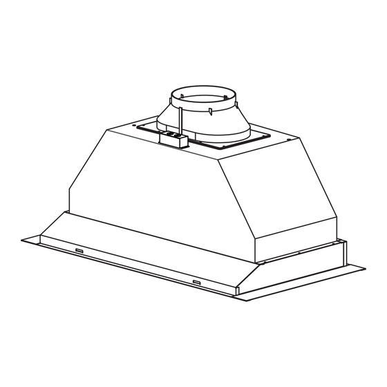
- Page 12 CAUTION: At least two installers are RH00529S RH00538S ” required due to the weight and size of the 1/16” 11/16 hood. 1. Remove support screw from top of Power Pack before installing into cabinet. FIG 2b 2. Install 8” round adapter to top of Power Pack using (4) M4 x 8 screws.
- Page 13 Blower On/Off Speed Selection Lights Off/Bright/Dim I I I BLOWER ON/OFF/SPEED SELECTION 0 is off, I is low speed, II is medium speed and III is high speed. LIGHTS OFF/BRIGHT/DIM 0 is off, I is bright, and II is dim.
- Page 14 2. Pull down on ¿ lter handle and pivot up until ¿ lter is À ush with bottom of power pack and locks into place. Replacing Decorative Mesh Filters: Hood Model: Part No. Qty. to Order RH00529S 50200037 FIG 4...
- Page 15 REPLACING LIGHT BULBS CAUTION: Light bulb becomes extremely hot when turned on. DO NOT touch bulb until switched off and cooled. Touching hot bulbs could cause serious burns. Make sure all power is turned off and bulbs are not hot. Remove by turning bulb counter clockwise.
- Page 16 TROUBLESHOOTING PROCEDURES FOR RH00529S AND RH00538S After installation, 1. The power source is not turned ON. 1. Make sure the circuit breaker and the unit’s the unit doesn’t power is ON. work. 2. The power line and the cable locking connector 2.
- Page 17 DESCRIPTION PART # Replacement Parts Light Bulb MR16 (GU10) 35W (each) Z0B-0023 Decorative Mesh Filter (each) 50200037 Optional Accessories Liner,36” (RH00529S) AK0806AS Liner,42” (RH00529S) AK0842AS Liner,48” (RH00538S) AK0848AS Liner,54” (RH00538S) AK0854AS Liner,60” (RH00538S) AK0860AS To order parts please call 1.888.750.1698...
Need help?
Do you have a question about the RH00529S and is the answer not in the manual?
Questions and answers