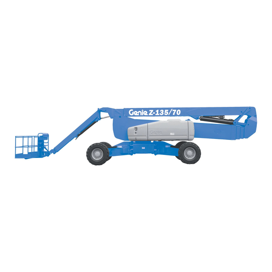
Genie Z-135/70 Operator's Manual
Hide thumbs
Also See for Z-135/70:
- Operator's manual (69 pages) ,
- Installation instructions manual (16 pages) ,
- Service and repair manual (253 pages)

Related Manuals for Genie Z-135/70


Summary of Contents for Genie Z-135/70
- Page 1 Operator’s Manual Z-135/70 with Maintenance Information Second Edition First Printing Part No. 114475...
-
Page 2: Table Of Contents
Only trained and authorized personnel shall be permitted to operate this machine. This manual should be considered a permanent part of your machine and should remain with the machine at all times. If you have any questions, call Genie Industries. Contents Page Introduction ..............1 Symbols and Hazard Pictorials Definitions .... -
Page 3: Introduction
Operator's Manual Introduction Owners, Users and Operators: Genie appreciates your choice of our machine for your application. Our number one priority is user safety, which is best achieved by our joint efforts. We feel that you make a major contribution to... - Page 4 Second Edition · First Printing Introduction Hazard Classification Intended Use Genie uses symbols, color coding and signal words This machine is intended to be used only to lift to identify the following: personnel, along with their tools and materials to an aerial work site.
-
Page 5: Symbols And Hazard Pictorials Definitions
Explosion Hazard or other high energy starting Platform downhill: Platform uphill: aids on machines 1 Retract primary 1 Lower primary equipped with 2 Retract/lower 2 Retract/lower glow plugs. secondary secondary 3 Lower primary 3 Retract primary Part No. 114475 Z-135/70... -
Page 6: Symbol And Hazard Pictorials Definitions
Pressure rating for Tire specification power to platform air line to platform attachment point Avoid contact. Tie-down Tie-down Weight of welder Wind speed instructions instructions reduces capacity Fire Hazard Fire extinguisher No step. Do not jump-start this battery. Z-135/70 Part No. 114475... -
Page 7: General Safety
Second Edition · First Printing Operator's Manual General Safety Safety signs and locations 133179 A 272 kg < = 272 kg 82546 B Part No. 114475 Z-135/70... - Page 8 Operator's Manual Second Edition · First Printing General Safety Safety signs and locations 133179 A 133180 A Z-135/70 Part No. 114475...
-
Page 9: Personal Safety
Operators must comply with employer, job site and governmental rules regarding the use of personal protective equipment. All PFPE must comply with applicable governmental regulations, and must be inspected and used in accordance with the PFPE manufacturer’s instructions. Part No. 114475 Z-135/70... -
Page 10: Work Area Safety
See the decals with the options. 350 to 500KV 7.6 m 500 to 750KV 10.6 m If using accessories, read, understand and obey the decals and instructions with the accessory. 750 to 1000KV 13.7 m Z-135/70 Part No. 114475... - Page 11 1 Lower the primary boom. 2 Retract/lower the secondary boom. 3 Retract the primary boom. If the tilt alarm sounds with the platform downhill: 1 Retract the primary boom. 2 Retract/lower the secondary boom. 3 Lower the primary boom. Part No. 114475 Z-135/70...
- Page 12 All surface or vehicle. personnel must be removed from the platform before attempting to free the platform using the Be sure all tires are in good condition and lug nuts ground controls. are properly tightened. Z-135/70 Part No. 114475...
- Page 13 Lower the platform entry mid-rail or close the entry gate before operating. Do not enter or exit the platform unless the machine is in the stowed position and the platform is at ground level. Part No. 114475 Z-135/70...
- Page 14 Do not operate a boom in the path of any crane unless the controls of the crane have been locked out and/or precautions have been taken to prevent any potential collision. Z-135/70 Part No. 114475...
- Page 15 Be sure all maintenance has been performed as specified in this manual and the appropriate Genie Explosion Hazard service manual. Keep sparks, flames Be sure all decals are in place and legible.
- Page 16 Do not cause a horizontal force or side load to the machine by raising or lowering a fixed or Maximum panel area: 3 m overhanging load. Electrocution Hazard: Keep pipes away from all energized electrical conductors. Z-135/70 Part No. 114475...
- Page 17 3 Rotate the turntable so that the boom is between the non-steer wheels. 4 Turn the key switch to the off position and remove the key to secure from unauthorized use. 5 Chock the wheels. Part No. 114475 Z-135/70...
-
Page 18: Legend
Second Edition · First Printing Legend 1 Square-end tire 8 Sliding mid-rail 2 Ground controls 9 Manual storage container 3 Secondary boom 10 Lanyard anchorage point 4 Primary boom 11 Foot switch 5 Jib boom 6 Platform 7 Platform controls Z-135/70 Part No. 114475... -
Page 19: Controls
6 LCD readout screen 22 Turntable rotate left/right 15 20A circuit breaker for 7 Red Emergency Stop button buttons system circuit 8 Glow plug button 16 Alarm 9 Key switch for off/ground/ 17 Platform level up/down platform selection buttons Part No. 114475 Z-135/70... - Page 20 15 20A circuit breaker for system circuit off. Pull out the red Emergency Stop button to the on position to operate the machine. 16 Alarm Z-135/70 Part No. 114475...
- Page 21 Push the jib boom down left button and the button and the jib boom will turntable will rotate to lower. the left. Push the turntable rotate right button and the turntable will rotate to the right. Part No. 114475 Z-135/70...
- Page 22 17 Fault indicator light 6 Drive enable button with 13 Steer mode select buttons 18 Low fuel indicator light indicator light with indicator lights 19 Check engine indicator light 7 Horn button 20 Red Emergency Stop button Z-135/70 Part No. 114475...
- Page 23 26 Dual axis proportional control handle for jib boom up/down and platform rotate left/right functions Part No. 114475 Z-135/70...
- Page 24 9 Generator button with indicator light (option) 16 Not used Press the generator button to turn the generator 17 Fault indicator light on. Press the button again to turn the generator off. Light on indicates a system fault. Z-135/70 Part No. 114475...
- Page 25 Press the left side of the rocker switch and the machine will steer to the left. Press the right side of the rocker switch and the machine will steer to the right. Part No. 114475 Z-135/70...
- Page 26 Move the control handle to the left and the turntable will rotate to the left. Move the control handle to the right and the turntable will rotate to the right. Z-135/70 Part No. 114475...
-
Page 27: Inspections
Scheduled maintenance inspections shall be performed by qualified service technicians, according to the manufacturer's specifications and the requirements listed in the responsibilities manual. Part No. 114475 Z-135/70... - Page 28 Electrical components, wiring and electrical cables Hydraulic hoses, fittings, cylinders and manifolds Fuel and hydraulic tanks Drive and turntable motors and drive hubs Boom wear pads Tires and wheels Engine and related components Limit switches and horn Rotation sensors Z-135/70 Part No. 114475...
- Page 29 After repairs are completed, the operator must perform a pre-operation inspection and function tests again before putting the machine into service. Part No. 114475 Z-135/70...
- Page 30 Result: The primary boom should extend and the axles are extended. retract normally. 17 Push and hold a function enable/speed select button and push the turntable rotate left button and then the turntable rotate right button. Result: The turntable should rotate normally. Z-135/70 Part No. 114475...
- Page 31 22 Simultaneously push and hold the auxiliary power button and push each boom function button. Note: To conserve battery power, test each function through a partial cycle. Result: All boom functions should operate. 23 Start the engine. Part No. 114475 Z-135/70...
- Page 32 The secondary boom should not extend until it is fully raised. 33 Push and hold the secondary boom down/retract button. Result: The secondary boom should fully retract and then lower. The secondary boom should not lower unless it is fully retracted. Z-135/70 Part No. 114475...
- Page 33 OR press the thumb rocker switch in the direction indicated by the yellow triangle. Result: The circle-end wheels should turn in the direction that the blue triangles point on the drive chassis. Part No. 114475 Z-135/70...
- Page 34 The circle-end wheels should triangle. turn in the direction that the blue triangles point on the drive chassis. Result: All wheels should turn in the direction that the yellow triangles point on the drive chassis. Z-135/70 Part No. 114475...
- Page 35 67 Move the drive/steer control handle off center. Result: The maximum achievable drive speed Result: No drive function should operate. with the primary boom extended should not exceed 30 cm per second. Note: The machine will travel 12 m in 40 seconds. Part No. 114475 Z-135/70...
- Page 36 If the drive speed with the jib boom extended and the primary boom extended exceeds 15 cm per second, immediately tag and remove the machine from service. 83 Retract the primary boom and the jib boom. Z-135/70 Part No. 114475...
-
Page 37: Workplace Inspection
It should be performed by the operator prior to moving the machine to the workplace. It is the operator's responsibility to read and remember the workplace hazards, then watch for and avoid them while moving, setting up and operating the machine. Part No. 114475 Z-135/70... - Page 38 82840 Ground Control Panel 27205 Arrow - Yellow 82841 Platform Control Panel 27206 Triangle - Blue 97705 Cosmetic - Genie Z-135/70 27207 Triangle - Yellow 97716 Label - Wheel Load 28159 Label - Diesel 97757 Label - Hydraulic Oil Level...
- Page 39 Second Edition · First Printing Operator's Manual Inspections Part No. 114475 Z-135/70...
-
Page 40: Operating Instructions
That means 4 Inspect the workplace. every new operator should perform a pre-operation inspection, function tests, and a workplace 5 Only use the machine as it was intended. inspection before using the machine. Z-135/70 Part No. 114475... -
Page 41: Emergency Stop
Attempting to start the engine when operating the auxiliary controls temperatures are below -18°C may require the use from the platform. of a booster battery. 4 Simultaneously hold the auxiliary power button and activate the desired function. Part No. 114475 Z-135/70... - Page 42 Use the color-coded direction arrows on the control panel. platform controls and the drive chassis to identify the direction the wheels will turn. Drive, steer and axle functions are not available from the ground controls. Z-135/70 Part No. 114475...
- Page 43 The term gradeability applies to the counterweight uphill configuration only. Be sure the boom is below horizontal and the platform is between the circle-end wheels. Move the drive speed select switch to machine on incline symbol. Part No. 114475 Z-135/70...
- Page 44 0.3 m ÷ 3.6 m = 0.083 x 100 = 8.3% grade If the slope exceeds the maximum uphill, downhill or side slope rating, then the machine must be winched or transported up or down the slope. See the Transport and Lifting section. Z-135/70 Part No. 114475...
- Page 45 If all functions stop operating, you may have exceeded the operational envelope. A trained operator on the ground will need to lower the platform from the ground controls. Please see the Service Bypass / Recovery Key Switch section in the service manual. Part No. 114475 Z-135/70...
- Page 46 Move the function override toggle switch to either side to operate the machine. Platform Overload Indicator Light Light flashing indicates the platform is overloaded and no functions will operate. Remove weight from the platform until the light goes off. Z-135/70 Part No. 114475...
- Page 47 3 Secure each U-bolt with 2 washers and 2 nuts. a strap e pipe cradle weldment b U-bolts middle platform c pipe cradle mount railing d upper platform g flat washers railing -inch nylock nuts Part No. 114475 Z-135/70...
- Page 48 Tip-over hazard. The weight of the pipe cradle assembly and the load in the pipe cradles may limit the maximum number of occupants in the platform. Maximum Pipe Cradle Capacity All models 90.7 kg Pipe Cradle Assembly Weight 9.5 kg Z-135/70 Part No. 114475...
- Page 49 8 Place the tube between the panel cradle and the platform floor. Insert the U-bolt through the floor, around the tube and into the panel cradle base. 9 Repeat above for the second set of parts. Part No. 114475 Z-135/70...
- Page 50 U-bolt mounting 3 Center the load on the platform. rubber slots bumper 1 4 Secure the load to the platform using the strap. Tighten the strap. panel decal cradle base hook piece padding clamp hook Z-135/70 Part No. 114475...
-
Page 51: Transport And Lifting Instructions
Free-wheel Configuration for Transportation regulations, other localized regulations, and their company policy. Winching Genie customers needing to containerize any lift Chock the wheels to prevent the machine from or Genie product should source a qualified rolling. freight forwarder with expertise in preparing,... - Page 52 Use a minimum of 6 chains. Adjust the rigging to prevent damage to the chains. Truck Bed Secondary boom width: Jib boom width: 66 cm 41 cm 12.97 m 3.07 m 1.31 m 3.3 m 5.84 m 4.25 m 7.65 m Z-135/70 Part No. 114475...
- Page 53 Adjust the rigging to prevent damage to the and straps or lines are sufficient to withstand machine and to keep the machine level. the machine weight. See the serial label for the machine weight. 1.5 m 1.4 m Part No. 114475 Z-135/70...
-
Page 54: Maintenance
Oil type 15W-40 responsibilities manual. Oil type - cold conditions 10W-30 Use only Genie approved replacement parts. Deutz BF4L2011 Engine Oil type 15W-40 Oil type - cold conditions 5W-30 Maintenance Symbols Legend Cummins B4.5C80 Engine... - Page 55 Do not overfill. Hydraulic oil specifications 6 Install the vent caps. Hydraulic oil type Chevron Rykon® Note: Adding terminal protectors and a corrosion Premium MV equivalent preventative sealant will help eliminate corrosion on the battery terminals and cables. Part No. 114475 Z-135/70...
- Page 56 Machines that have been out of service for more than three months must receive the quarterly inspection before they are put back into service. Z-135/70 Part No. 114475...
-
Page 57: Specifications
Platform dimensions, 1.8 m (length x width) 1.8 m x 76 cm Platform dimensions, 2.4 m Continuous improvement of our products is a Genie (length x width) 2.4 m x 91 cm policy. Product specifications are subject to change without notice or obligation. - Page 58 Operator's Manual Second Edition · First Printing Specifications Z-135/70 Range of Motion Z-135/70 Part No. 114475...
- Page 59 Genie North America Phone 425.881.1800 Toll Free USA and Canada 800.536.1800 Fax 425.883.3475 Genie Australia Pty Ltd. Phone +61 7 3375 1660 Fax +61 7 3375 1002 Genie China Genie Scandinavia Phone +86 21 53852570 Phone +46 31 575100...
Need help?
Do you have a question about the Z-135/70 and is the answer not in the manual?
Questions and answers