Table of Contents
Advertisement
TECHNICAL DATA
& SERVICE MANUAL
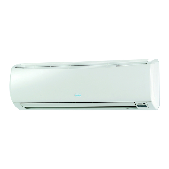
INDOOR UNIT:
SPLIT SYSTEM AIR CONDITIONER
Model No.
MCW1B5XAB
MCW2B5XAB
MCW3B5XAB
MCW4B5XAB
MPW1B5XAA
MPW2B5XAA
MPW3B5XAA
MPW4B5XAA
MCW1B5XAB
MCW2B5XAB
MCW3B5XAB
MCW4B5XAB
Product Code No.
38.7104.026
38.7104.027
38.7104.028
38.7104.029
38.7104.040
38.7104.043
38.7104.045
38.7104.047
0.8180.566.1
MPW1B5XAA
MPW2B5XAA
MPW3B5XAA
MPW4B5XAA
April 2011
Advertisement
Table of Contents


Need help?
Do you have a question about the MCW1B5XAB and is the answer not in the manual?
Questions and answers