Table of Contents
Advertisement
Congratulations on owning a Scag mower! This manual contains the operating
instructions and safety information for your Scag mower. Reading this manual
can provide you with assistance in maintenance and adjustment procedures to
keep your mower performing to maximum efficiency. The specific models that
this book covers are listed on the inside cover. Before operating your machine,
please read all the information enclosed.
© 2013
Scag Power Equipment
Division of Metalcraft of Mayville, Inc.
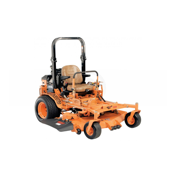
OPERATOR'S
MANUAL
Turf Tiger
Models:
STT52V-26CH-EFI
STT61V-25KA
STT61V-26CH-EFI
STT61V-26DFI
STT61V-35BVAC
STT72V-26CH-EFI
STT72V-26DFI
STT72V-35BVAC
PART NO. 03364
PRINTED 9/2013
PRINTED IN USA
Advertisement
Table of Contents

Related Manuals for Scag Power Equipment Turf Tiger STT52V-26CH-EFI


Summary of Contents for Scag Power Equipment Turf Tiger STT52V-26CH-EFI
- Page 1 The specific models that this book covers are listed on the inside cover. Before operating your machine, please read all the information enclosed. © 2013 PART NO. 03364 Scag Power Equipment PRINTED 9/2013 Division of Metalcraft of Mayville, Inc. PRINTED IN USA...
- Page 2 WARNING FAILURE TO FOLLOW SAFE OPERATING PRACTICES MAY RESULT IN SERIOUS INJURY OR DEATH. • Read this manual completely as well as other manuals that came with your mower. • DO NOT operate on steep slopes. To check a slope, attempt to back up it (with the cutter deck down).
-
Page 3: Table Of Contents
Table of Contents Table of Contents SECTION 1 - GENERAL INFORMATION ...................1 1.1 INTRODUCTION ............................1 1.2 DIRECTION REFERENCE ...........................1 1.3 SERvICING THE ENGINE AND DRIvE TRAIN COMPONENTS ..............1 1.4 SYMBOLS ..............................2 SECTION 2 - SAFETY INFORMATION ..................3 2.1 INTRODUCTION ............................3 2.2 SIGNAL WORDS ............................3 2.3 BEFORE OPERATION CONSIDERATIONS ....................3 2.4 OPERATION CONSIDERATIONS ........................4... - Page 4 Table of Contents SECTION 5 - TROUBLESHOOTING CUTTING CONDITIONS ..........21 SECTION 6 - ADJUSTMENTS ....................24 6.1 PARKING BRAKE ADJUSTMENT ......................24 6.2 TRAvEL ADJUSTMENTS ..........................25 6.3 THROTTLE CONTROL AND CHOKE ADJUSTMENTS ................26 6.4 BELT ADJUSTMENT ..........................26 6.5 BELT ALIGNMENT .............................27 6.6 CUTTER DECK ADJUSTMENTS ......................27 6.7 CUSTOM-CUT BAFFLE ADJUSTMENT ....................29 6.8 ELECTRIC CLUTCH ADJUSTMENT ......................30 SECTION 7 -...
- Page 5 Table of Contents BDP-16A HYDRAULIC PUMP ASSEMBLY WITH COOLING FAN (26DFI & 35BvAC) .........70 ELECTRICAL SYSTEM - 25KA - KAWASAKI ....................72 ELECTRICAL SYSTEM - 26CH-EFI - KOHLER ....................74 ELECTRICAL SYSTEM - 26DFI - KAWASAKI ....................76 ELECTRICAL SYSTEM - 35BvAC - BRIGGS & STRATTON .................78 REPLACEMENT DECALS AND INFORMATION PLATES ................80 STT ELECTRICAL SCHEMATIC (25KA - KAWASAKI) ..................82 STT ELECTRICAL SCHEMATIC (26CH-EFI - KOHLER) ................83...
- Page 6 Table of Contents...
-
Page 7: General Information
Scag service parts. All information is based upon product information available - IMPORTANT - at the time of approval for printing. Scag Power Equipment The replacement of any part on this product reserves the right to make changes at any time without by other than the manufacturer's authorized notice and without incurring any obligation. -
Page 8: Symbols
Section 1 SYMBOLS SYMBOL DESCRIPTION SYMBOL DESCRIPTION Choke Transmission Parking Brake Spinning Blade 48071S On/Start Spring Tension on Idler Off/Stop Falling Hazard Thrown Object Hazard Fast Slow Continuously Variable - Linear Cutting Element - Basic Symbol Pinch Point Cutting Element - Engage 481039S Hour meter/Elapsed Operating Hours Cutting Element - Disengage... -
Page 9: Safety Information
Section 2 SAFETY INFORMATION INTRODUCTION DANGER Your mower is only as safe as the operator. Carelessness or operator error may result in serious bodily injury The signal word “DANGER” denotes that an extremely or death. Hazard control and accident prevention are hazardous situation exists on or near the machine that dependent upon the awareness, concern, prudence, and could result in high probability of death or irreparable injury... -
Page 10: Operation Considerations
Section 2 DO NOT allow children to ride or play on the Be sure the interlock switches are functioning machine, it is not a toy. correctly. Clear the area to be mowed of objects that could be Fuel is flammable; handle it with care. Fill the fuel picked up and thrown by the cutter blades. - Page 11 Section 2 Reduce speed and exercise extreme caution on NEVER raise the deck with the blades engaged. slopes and in sharp turns to prevent tipping or loss Take all possible precautions when leaving the of control. Be especially cautious when changing machine unattended, such as disengaging the directions on slopes.
-
Page 12: Roll-Over Protection System
Section 2 Use care when approaching blind corners, shrubs, Lower the roll bar only when absolutely necessary. trees, or other objects that may obscure vision. To lower the roll bar, remove the hairpin cotter pins NEVER leave the machine running unattended. and remove the two (2) lock pins. - Page 13 Section 2 WARNING Failure to properly inspect and maintain the seat belt can cause serious injury or loss of life. Check the full length of the seat belt webbing for cuts, wear, fraying, dirt and stiffness. See Figure 2-3. Figure 2-4. Slope Angle Graph Check the seat belt webbing in areas exposed to ultra violet rays from the sun or extreme dust or...
-
Page 14: Maintenance Considerations & Storage
Section 2 MAINTENANCE CONSIDERATIONS & WARNING STORAGE Never make adjustments to the machine with the Hydraulic fluid is under high pressure and can engine running unless specifically instructed to do penetrate skin causing injury. If hydraulic fluid so. If the engine is running, keep hands, feet, and is injected into the skin, it must be surgically clothing away from moving parts. -
Page 15: Safety And Instructional Decals
Section 2 SAFETY AND INSTRUCTIONAL DECALS WARNING INSTALL BELT COvER BEFORE OPERATING MACHINE READ OPERATOR'S MANUAL 483402 483407 483402 483407 FORWARD REvERSE 481568 WARNING 483406 Operation of this equipment may create sparks that can start res around dry vegetation. A spark arrestor may be required. -
Page 16: Specifications
Section 3 SPECIFICATIONS ENGINE General Type ....................Heavy Duty Industrial/Commercial Gasoline Model: Scag Model STT61V-25KA ......................Kawasaki FD750D Scag Model STT52V-26CH-EFI, STT61V-26CH-EFI, STT72V-26CH-EFI ......Kohler Command ECH749 Scag Model STT61V-26DFI, STT72V-26DFI .................. Kawasaki FD791D Scag Model STT61V-35BVAC, STT72V-35BVAC .............Briggs & Stratton Vanguard Displacement: Kohler 26CH-EFI (ECH749) .......................... -
Page 17: Power Head
Section 3 POWER HEAD Drive System ....Hydraulic Drive with Two Variable Displacement Pumps and Two Cast-Iron High Torque Motors Hydrostatic Pumps ..............Two Hydro-Gear™ 16 cc/rev. Pumps with Dump Valves Drive Wheel Motors: ............Two Parker Model TG 15 cu. inch Cast-Iron High Torque Motors Steering/Travel Control ................... -
Page 18: Hydraulic System
Section 3 HYDRAULIC SYSTEM Hydraulic Oil Filter ......................10 Micron Spin-on Element Type Hydraulic Reservoir ........................Nylon; 3 Quart Capacity WEIGHTS AND DIMENSIONS 72vS Length..................83" .......87.5" ........90" Tracking Width ................51" ........ 56" ........56" Overall Width w/chute down ............64.5" ......73.5" ........83" Overall Width w/chute up ............ -
Page 19: Operating Instructions
Section 4 OPERATING INSTRUCTIONS Mower Deck Switch (Figure 4-1). Used to engage CAUTION and disengage the mower drive system. Pulling up on the switch will engage the deck drive. Pushing down on the switch will disengage the deck drive. Do not attempt to operate this mower unless you Engine Choke Control (Figure 4-1). -
Page 20: Safety Interlock System
Section 4 voltmeter (Figure 4-1). Deck Lift Foot Lever (Figure 4-1). Indicates the condition of Used to raise and lower the cutter deck. Push full forward to lock in the charging system. When the engine is running, in normal operating conditions, the needle should be in the transport position. -
Page 21: Initial Run-In Procedures
Section 4 INITIAL RUN-IN PROCEDURES Allow engine to warm before operating the mower. GROUND TRAvEL AND STEERING FIRST DAY OF USE OR APPROxIMATELY 20 HOURS Check all belts for proper alignment and wear at 2, 4 - IMPORTANT - and 8 hours. If you are not familiar with the operation of a machine with lever steering and/or hydrostatic Change the engine oil and oil filter after the first 20... -
Page 22: Engaging The Deck Drive (Cutter Blades)
Section 4 - IMPORTANT - To stop the reverse travel, allow the steering control levers to return to the neutral position. If the mower is to be Do not travel forward over a curb. The mower will parked, place the handles in the neutral lock position and hang up on the curb. -
Page 23: Hillside Operation
Section 4 HILLSIDE OPERATION AFTER OPERATION Wash the entire mower after each use. Do not WARNING use high pressure spray or direct the spray onto electrical components. - IMPORTANT - DO NOT operate on steep slopes. To check a slope, attempt to back up it (with the cutter deck down). -
Page 24: Moving Mower With Engine Stopped
Section 4 4.11 MOvING MOWER WITH ENGINE Keep mower and discharge chute clean. STOPPED When mowing wet or tall grass, mow the grass twice. Raise the mower to the highest setting for the first pass and then make a second pass to the desired To “free-wheel”... -
Page 25: Adjusting The Steering Levers
Section 4 Insert the lanyard pin into the cutting height index at the desired cutting height. Push forward on the deck TENSION lift foot lever, hold in place and pull back on the deck KNOB release lever. See Figure 4-6. Slowly release the foot pedal. -
Page 26: Towing (Optional Hitch Accessory)
Section 4 4.16 TOWING (OPTIONAL HITCH ACCESSORY) NEVER allow children or others in or on towed equipment. Tow only with a machine that has a hitch designed for towing. Do not attach towed equipment except at the hitch point. Follow manufacturer's recommendations for weight limit for towed equipment. -
Page 27: Troubleshooting Cutting Conditions
Section 5 TROUBLESHOOTING CUTTING CONDITIONS CONDITION CAUSE CURE STRINGERS - OCCASIONAL Low engine RPM Run engine at full RPM BLADES OF UNCUT GRASS Ground speed too fast Slow speed to adjust for conditions Wet grass Cut grass after it has dried out Dull blades, incorrect sharpening Sharpen blades Deck plugged, grass accumulation... - Page 28 Section 5 TROUBLESHOOTING CUTTING CONDITIONS (CONT'D) CONDITION CAUSE CURE U N E v E N C U T O N F L AT Lift worn from blade Replace blade GROUND - WAvY HIGH-LOW APPEARANCE, SCALLOPED Blade upside down Mount with cutting edge toward ground CUT, OR ROUGH CONTOUR Deck plugged, grass accumulation Clean underside of deck...
- Page 29 Section 5 TROUBLESHOOTING CUTTING CONDITIONS (CONT'D) CONDITION CAUSE CURE SCALPING - BLADES HITTING Low tire pressures Check and adjust pressures DIRT OR CUTTING vERY CLOSE TO THE GROUND Ground speed too fast Slow speed to adjust for conditions May need to reduce ground speed, raise Cutting too low cutting height, change direction of cut, and/or change pitch and level...
-
Page 30: Adjustments
Section 6 ADJUSTMENTS PARKING BRAKE ADJUSTMENT - NOTe - If this procedure does not achieve proper brake adjustment, please contact your authorized Scag WARNING dealer. LOOSEN HERE Do not operate the mower if the parking brake is not operable. Possible severe injury could result. -
Page 31: Travel Adjustments
Section 6 TRAvEL ADJUSTMENTS LOOSEN HERE Neutral or tracking adjustments will need to be made if: A. The steering control levers are in the neutral position and the machine creeps forward or backward. See Neutral Adjustment on page 25 (next procedure). B. -
Page 32: Throttle Control And Choke Adjustments
Section 6 - NOTe - Actuate the steering control levers forward and reverse several times and return them to the neutral If after making the adjustment as outlined in step position. 1A, the machine creeps forward or backward, perform the neutral adjustment. See Neutral Check that the drive wheels remained in neutral and Adjustment on page 25. -
Page 33: Belt Alignment
Section 6 WARNING If the pump drive belt fails, steering control will be lost which could result in serious injury or death. ADJUST HERE Replace the pump drive belt as needed or every 400 hours / 2 years, whichever occurs first. LOOSEN HERE BELT ALIGNMENT... - Page 34 Section 6 LANYARD JAM NUT LOOSEN HERE ADJUST HERE 390S0174-1 390S014A-2 HEIGHT ADJUSTMENT PEDAL Figure 6-6. Cutter Deck Level Adjustment Using a wrench on the jam nut turn the adjusting Figure 6-7. Cutter Deck Height Adjustment rods until the proper pitch is obtained on both the RH and the LH side of the cutter deck.
-
Page 35: Custom-Cut Baffle Adjustment
Section 6 CUSTOM-CUT BAFFLE ADJUSTMENT To adjust the Custom-Cut Baffle height: Place the cutter deck in the transport position. The Custom-Cut Baffle is designed to deliver optimum airflow and superior cutting performance in any type of Remove the hardware securing the Custom-Cut grass. -
Page 36: Electric Clutch Adjustment
Section 6 ELECTRIC CLUTCH ADJUSTMENT ADJUSTMENT NUTS The electric clutch serves two functions in the operation of the mower. In addition to starting and stopping the power flow to the cutter blades, the clutch also acts as a brake to assist in stopping blade rotation when the PTO is switched off or the operator presence circuit is interrupted. -
Page 37: Maintenance
Section 7 MAINTENANCE MAINTENANCE CHART - RECOMMENDED SERvICE INTERvALS HOURS PROCEDURE COMMENTS BREAK-IN (FIRST 10) Check all hardware for tightness Check hydraulic oil level See paragraph 7.3 C h e c k a l l b e l t s f o r p r o p e r See paragraph 7.8 alignment Check coolant level... -
Page 38: Lubrication
Section 7 MAINTENANCE CHART - RECOMMENDED SERvICE INTERvALS (CONT'D) HOURS PROCEDURE COMMENTS BREAK-IN (FIRST 10) Apply grease to fittings See paragraph 7.2 Check hardware for tightness Change engine oil filter See paragraph 7.4 Check hydraulic oil level See paragraph 7.3 Replace engine fuel filter See paragraph 7.5 Drain hydraulic system and replace... - Page 39 Section 7 GREASE FITTING LUBRICATION LUBRICANT / INTERVAL LITHIUM MP WHITE GREASE 2125 ( 40 HOURS / WEEKLY ) CHASSIS GREASE ( 100 HOURS / BI-MONTHLY ) CHASSIS GREASE ( 200 HOURS / MONTHLY ) CHASSIS GREASE ( 500 HOURS / YEARLY ) 390S0145-2 Figure 7-1.
-
Page 40: Hydraulic System
Section 7 HYDRAULIC SYSTEM - IMPORTANT - The hydraulic oil should be changed if you notice the presence of water or a rancid odor to the A. CHECKING HYDRAULIC OIL LEvEL hydraulic oil. The hydraulic oil level should be checked after the first 10 Park the mower on a level surface and stop the hours of operation. -
Page 41: Engine Oil
Section 7 C. CHANGING HYDRAULIC OIL FILTER ENGINE OIL FILTER ELEMENT The hydraulic oil filter should be changed after every 500 hours of operation or annually, whichever occurs first. Remove the oil filter element and properly discard it. See Figure 7-3. Fill the new filter with clean oil and install the filter. -
Page 42: Engine Air Cleaner
Section 7 Replace gas cap and tighten the fuel cap until it FILLER NECK ratchets. INSERT B. REPLACING IN-LINE FUEL FILTER ELEMENTS The engine fuel filter should be replaced after every 500 FUEL LEVEL hours of operation or annually, whichever occurs first. See Figure 7-7. -
Page 43: Battery
Section 7 - NOTe - WARNING In extremely dusty conditions it may be necessary to check the element once or twice daily to prevent engine damage. Electric storage battery fluid contains sulfuric acid which is POISON and can cause SEvERE Unhook the clamps securing the air cleaner cover to CHEMICAL BURNS. -
Page 44: Drive Belts
Section 7 CUTTER BLADES WARNING A. BLADE INSPECTION BATTERIES PRODUCE ExPLOSIvE GASES. Charge the battery in a well ventilated space so BLADE INSPECTION gases produced while charging can dissipate. Remove the ignition key before servicing the blades. Raise the mower deck to the highest position. Place Charging rates between 3 and 50 amperes are satisfactory the lanyard pin in the highest cutting height position if excessive gassing or spewing of electrolyte does not... - Page 45 Section 7 - NOTe - - NOTe - DO NOT sharpen the blades beyond 1/3 of the The front of the machine will have to be raised width of the blade. See Figure 7-8. slightly to remove the blade bolt from the cutter spindle.
-
Page 46: Tires
Section 7 Install the spacer onto the blade bolt and insert the Visually check that the lubricant level is up to the bolt into the cutter spindle shaft. bottom edge of the check plug hole. If lubricant is low, add SAE 80W90 lubricant through the check Install the hex nut to the blade bolt at the top of the plug hole in the gearbox until it is level with the cutter spindle. -
Page 47: Body, Deck, And Upholstery
Section 7 - NOTe - Fill to Bottom of Filler Neck Check the radiator for excessive debris and clean with compressed air. Never spray a hot engine with water, use only compressed air to remove debris. Re-install the debris screen to the radiator. C. -
Page 48: Notes
Section 8 NOTES... -
Page 49: Illustrated Parts List
Section 8 ILLUSTRATED PARTS LIST SCAG APPROvED ATTACHMENTS AND ACCESSORIES Attachments and accessories manufactured by companies other than Scag Power Equipment are not approved for use on this machine. Scag approved attachments and accessories: • GC-3B (p/n 900J, 900K) - Requires a 900W (52 STT Install Kit) or 900X (61 STT/SCZ Install Kit) •... -
Page 50: 52V Cutter Deck
Section 8 52v CUTTER DECK 44 61 63 85 86 2012 STT 52CD... - Page 51 Section 8 52v CUTTER DECK Ref. Ref. Part No. Description Part No. Description 483378 Spring, Discharge Chute 461859 Cutter Deck Velocity Plus 482295 Wheel, Anti-Scalp 04003-40 Bolt, Carriage 7/16-14 x 1-1/4” 482878 Cutter Blade, 18” 04019-04 Nut, Hex Serr. Flng 3/8-16 482486 Gearbox Assm, Deck Drive 481625-01...
-
Page 52: 61V & 72Vs Cutter Decks
Section 8 61v & 72vS CUTTER DECKS 14 15 16 72V Only 54 55 2012 STT61V CD... - Page 53 Section 8 61v & 72vS CUTTER DECKS Ref. Ref. Part No. Description Part No. Description 424841 Baffle, Custom Cut 61V 481625-01 Wing Nut, 3/8-16 424917 Baffle, Custom Cut 72V 462360 Belt Cover Assembly 462398 Belt Cover Assy., RH 04003-23 Bolt, Carriage 3/8-16 x 1” 424209 Discharge Baffle 61V 462397...
-
Page 54: Cutter Deck Controls
Section 8 CUTTER DECK CONTROLS CUTTER DECK STT2006CDC... - Page 55 Section 8 CUTTER DECK CONTROLS Ref. Part No. Description 461929 Lever Assembly, Deck Level 481764 Link, Deck Lift 481765 Rod End, Female - 1/2-20 RH 481766 Rod End, Female - 1/2-20 LH 04020-27 Nut, Jam 1/2-20 RH 04020-28 Nut, Jam 1/2-20 LH 04021-09 Nut, 3/8-16 Elastic Stop 482429...
-
Page 56: Sheet Metal Components
Section 8 SHEET METAL COMPONENTS STT 2011 SMC... - Page 57 Section 8 SHEET METAL COMPONENTS Ref. Ref. Part No. Description Part No. Description 04050-01 Retaining Ring, .625” Ext. “E” 451481 Fender Weldment, RH 484341 Grip, Seat Latch 04001-09 Bolt, Hex Head, 5/16-18 x 1, Zinc 9240 Cup Holder Assembly 483371 Spring, Seat Latch 491731 Lever Assembly, Seat Release...
-
Page 58: Stt Roll-Over Protection System
Section 8 STT ROLL-OvER PROTECTION SYSTEM... - Page 59 Section 8 STT ROLL-OvER PROTECTION SYSTEM Ref. Part No. Description 462210 STT, ROPS 04001-87 Bolt, Hex Head 1/2-13 x 4” 04021-19 Nut, Center Lock 1/2-13 04040-13 Flatwasher, 1/2-.562 x 1.375 x .109 484168 Pin Assembly (incl. #9 & #10) 04001-163 Bolt, Hex Head 1/2-13 x 3-3/4”...
-
Page 60: Stt Suspension Seat
Section 8 STT SUSPENSION SEAT Ref. Part No. Description 922A Suspension Seat Assembly w/seat belt 484709 Armrest Kit, LH 484717 Seat Belt Kit 484711 Recliner Knob Kit 484710 Armrest Kit, RH 484712 Back Cover 481638 Seat Switch 484713 Track Kit 484714 Suspension Knob Kit 484708... -
Page 61: Notes
Section 8 NOTES... - Page 62 Section 8 DECK DRIvE COMPONENTS 6 64 63 62 24 49 50 28 29 30 25 26 27 Frame STT 2011 DDC...
-
Page 63: Deck Drive Components
Section 8 DECK DRIvE COMPONENTS Ref. Ref. Part No. Description Part No. Description 04019-02 Nut, Serrated Flange 1/4-20 423925 Belt Guard, Rear 04003-07 Bolt, Carriage 1/4-20 x 1/2” 481531 Hinge, Belt Guard 04021-22 Nut, Elastic Stop 5/16-18 Grade 8 481309 Latch, Hood 04001-176 Bolt, Hex Head 5/16-18 x 1-3/4”... -
Page 64: Engine And Attaching Parts - Kohler
Section 8 ENGINE AND ATTACHING PARTS - KOHLER REF. PUMP MTG. WELDMENT STT 2013 EAPKH FRAME... - Page 65 Section 8 ENGINE AND ATTACHING PARTS - KOHLER Ref. Part No. Description 425933 Muffler Guard 04017-05 Screw, Hex Serrated Flange 1/4-20 x 3/4” Muffler, Part Of Engine (Available only through Kohler) 482510 Oil Drain Extension 04110-01 U-Nut, 1/4-20 424691 Rear Cover 484565 Hour Meter **485036...
-
Page 66: Engine & Attaching Parts - 25Ka, 26Dfi Kawasaki & 35Bvac
Section 8 ENGINE & ATTACHING PARTS - 25KA, 26DFI KAWASAKI & 35BvAC 18 19 REF. PUMP MTG. WELDMENT STT 2013 EAPKA FRAME... - Page 67 Section 8 ENGINE & ATTACHING PARTS - 25KA, 26DFI KAWASAKI & 35BvAC Ref. Part No. Description 451378 Muffler Guard (Kawasaki) 425933 Muffler Guard (Briggs & Stratton) 04017-05 Screw, Hex Serrated Flange 1/4-20 x 3/4” 482699 Muffler (Kawasaki) 483819 Muffler (Briggs & Stratton) 483857 Spark Arrestor Assembly, Briggs &...
-
Page 68: Brake And Steering Components
Section 8 BRAKE AND STEERING COMPONENTS TO RH PUMP TO LH PUMP 61 59 STT2006B&SC REV 1... - Page 69 Section 8 BRAKE AND STEERING COMPONENTS Ref. Ref. Part No. Description Part No. Description 48343-04 Clevis, Traction Control 484376 Grip, Handle Bar 04064-02 Pin, Clevis 3/8-16 x 1-1/16” 462402 Handle Bar, LH (Includes item 1) 04061-02 Pin, Cotter 3/32 x .75” 462403 Handle Bar, RH (Includes item 1) 04004-34...
-
Page 70: Stt Hydraulic System
Section 8 STT HYDRAULIC SYSTEM DUMP VALVE 43 (2) 43 (2) 44 45 17 2012 STT HS.eps... - Page 71 Section 8 STT HYDRAULIC SYSTEM Ref. Ref. Part No. Description Part No. Description 423485 Support Bracket, Hydraulic Tank 04110-01 U-Nut 1/4-20 484459 Hose Assembly, Pump 48136-13 Hose Clamp, 0.69” Dia. 48572-04 Union, 3/4”-16 JIC x 3/4”-16 O-Ring 04001-03 Bolt, Hex Head 1/4-20 x 2.0” 04001-59 Bolt, Hex Head, 1/4-20 x 1-1/4”...
-
Page 72: Stt Fuel System
Section 8 STT FUEL SYSTEM Kohler Briggs & Stratton - 35BVAC To Fuel Pump Kawasaki - FD750D Carburetor Kawasaki - FD791D Injector Fuel Return To Engine Purge Port Fuel Tank Tank Purge 2014 STT FS - EPA Phase 3.eps... - Page 73 Section 8 STT FUEL SYSTEM Ref. Part No. Description 484251 Fuel Gauge Assembly 484242 Seal, Fuel Gauge 484286 Fuel Cap, Tethered 484297 Fuel Cap w/Tethered - California Models Only (not shown) 04003-02 Bolt, Carriage 1/4-20 x 3/4” 462384 Fuel Tank Assembly, Low Perm. - STT (incl. # 1, 2, 8, 9, 30, 31) 462385 Fuel Tank Assembly, Low Perm.
-
Page 74: Bdp-16A Hydraulic Pump Assembly
Section 8 BDP-16A HYDRAULIC PUMP ASSEMBLY PORT "A" SIDE PORT "B" SIDE... - Page 75 Section 8 BDP-16A HYDRAULIC PUMP ASSEMBLY Ref. Part No. Description HG70740 Overhaul Seal Kit HG70402 Charge Relief Kit HG72158 Cylinder Block Kit - 16cc HG51462 Thrust Ball Bearing Assembly HG51436 Variable Swashplate HG2000015 Slot Guide HG2000014 Trunnion Arm HG2000025 Block Spring HG2000024 Block Thrust Washer HG2000032...
-
Page 76: Bdp-16A Hydraulic Pump Assembly With Cooling Fan (26Dfi & 35Bvac)
Section 8 BDP-16A HYDRAULIC PUMP ASSEMBLY with COOLING FAN (26DFI & 35BvAC) PORT "A" SIDE PORT "B" SIDE... - Page 77 Section 8 BDP-16A HYDRAULIC PUMP ASSEMBLY with COOLING FAN (26DFI & 35BvAC) Ref. Part No. Description HG70740 Overhaul Seal Kit HG52059 Shroud HG72158 Cylinder Block Kit - 16cc HG51462 Thrust Ball Bearing Assembly HG51436 Variable Swashplate HG2000015 Slot Guide HG2000014 Trunnion Arm HG2000025 Block Spring...
-
Page 78: Electrical System - 25Ka - Kawasaki
Section 8 ELECTRICAL SYSTEM - 25KA - KAWASAKI STT 2012 ESKA... - Page 79 Section 8 ELECTRICAL SYSTEM - 25KA - KAWASAKI Ref. Part No. Description 481755 Ammeter 48298 Fuse, 20 AMP 483366 Key, Ignition 462069 Key Assembly w/Fob 48017-04 Nut, Hex 5/8-32 48017-03 Lockwasher, 5/8” Internal 461916 Instrument Panel, Top w/Decals 48798 Key Switch 483957 Switch, PTO 483013...
-
Page 80: Electrical System - 26Ch-Efi - Kohler
Section 8 ELECTRICAL SYSTEM - 26CH-EFI - KOHLER STT 2012 ESCHEFI... - Page 81 Section 8 ELECTRICAL SYSTEM - 26CH-EFI - KOHLER Ref. Part No. Description 484655 Wire Harness, STT 26CH-EFI Air-Cooled 48298 Fuse, 20 AMP 483366 Key, Ignition 462069 Key Assembly w/Fob 48017-04 Nut, Hex 5/8-32 48017-03 Lockwasher, 5/8” Internal 461916 Instrument Panel, Top w/Decals 48798 Key Switch 483957...
-
Page 82: Electrical System - 26Dfi - Kawasaki
Section 8 ELECTRICAL SYSTEM - 26DFI - KAWASAKI STT 2012 ESKA-DFI... - Page 83 Section 8 ELECTRICAL SYSTEM - 26DFI - KAWASAKI Ref. Part No. Description 481755 Ammeter 48298 Fuse, 20 AMP 483366 Key, Ignition 462069 Key Assembly w/Fob 48017-04 Nut, Hex 5/8-32 48017-03 Lockwasher, 5/8” Internal 461916 Instrument Panel, Top w/Decals 48798 Key Switch 483957 Switch, PTO 48788...
-
Page 84: Electrical System - 35Bvac - Briggs & Stratton
Section 8 ELECTRICAL SYSTEM - 35BVAC - BRIGGS & STRATTON STT 2012 ESKH... - Page 85 Section 8 ELECTRICAL SYSTEM - 35BVAC - BRIGGS & STRATTON Ref. Part No. Description 484654 Wire Harness, Briggs & Stratton 482849 Wire Harness Adapter Briggs & Stratton (not shown) 48298 Fuse, 20 AMP 483366 Key, Ignition 462069 Key Assembly w/Fob 48017-04 Nut, Hex 5/8-32 48017-03...
-
Page 86: Replacement Decals And Information Plates
Section 8 REPLACEMENT DECALS AND INFORMATION PLATES 48404 Hea vy- Duty FORWARD Comm e rcial REvERSE 481568 481971 WARNING INSTALL BELT COvER BEFORE OPERATING MACHINE READ OPERATOR'S MANUAL MOWER DECK PULL OUT TO ENGAGE PUSH IN TO DISENGAGE START MOWER DECK PULL OUT TO ENGAGE 482508 PUSH IN TO DISENGAGE... - Page 87 Section 8 REPLACEMENT DECALS AND INFORMATION PLATES Ref. Part No. Description 483192 Decal, Danger - Spinning Blades 483406 Decal, Warning - Rotating Blades 483200 Decal, 52 Velocity Plus 483201 Decal, 61 Velocity Plus 481956 Decal, 72 Advantage 483693 Decal, 72 Velocity Plus 483397 Decal, Fuel Tank 484293...
-
Page 88: Stt Electrical Schematic (25Ka - Kawasaki)
Section 8 STT ELECTRICAL SCHEMATIC (25KA - KAWASAKI) L.H. NEUTRAL SWITCH RELAY GRN W/BLK STRIPE DIODE GRN W/WHT STRIPE GREEN BROWN RED W/YEL STRIPE BRAKE SEAT PINK INTERLOCK SWITCH SWITCH WATER TEMP WHT W/BLK STRIPE BLACK GAUGE BLACK 20 AMP FUSE 20 AMP FUSE YELLOW YELLOW... -
Page 89: Stt Electrical Schematic (26Ch-Efi - Kohler)
Section 8 STT ELECTRICAL SCHEMATIC (26CH-EFI - KOHLER) L.H. NEUTRAL SWITCH BRAKE SEAT BROWN PINK INTERLOCK SWITCH SWITCH RELAY GREEN RED W/YEL STRIPE 20 AMP FUSE PINK ORANGE BROWN GRN W/WHT STRIPE BLUE BLK W/ORANGE STRIPE PINK BLACK WHITE MODULE WHITE STARTER “B”+ PLUG... -
Page 90: Electrical Schematic (26Dfi - Kawasaki)
Section 8 ELECTRICAL SCHEMATIC (26DFI - KAWASAKI) L.H. NEUTRAL SWITCH RELAY GRN W/BLK STRIPE DIODE GRN W/WHT STRIPE GREEN BRAKE RED W/YEL STRIPE BROWN PINK SEAT INTERLOCK SWITCH SWITCH WATER TEMP WHT W/BLK STRIPE BLACK GAUGE BLACK 20 AMP FUSE 20 AMP FUSE YELLOW YELLOW... -
Page 91: Stt Electrical Schematic (35Bvac Briggs & Stratton)
Section 8 STT ELECTRICAL SCHEMATIC (35BvAC Briggs & Stratton) L.H. NEUTRAL SWITCH BROWN BRAKE PINK SEAT INTERLOCK SWITCH SWITCH RELAY GRN W/BLK STRIPE DIODE GRN W/WHT STRIPE GREEN RED W/YEL STRIPE 20 AMP FUSE 20 AMP FUSE YELLOW YELLOW PINK GRN W/BLK STRIPE MODULE WHITE... -
Page 92: Limited Warranty - Commercial Equipment
Cutter decks are warranted against cracking for a period of three (3) years. (parts and labor 1st and 2nd year; parts only 3rd year.) The repair or replacement of the cutter deck will be at the option of Scag Power Equipment. We reserve the right to request compo- nents for evaluation. - Page 93 © 2013 Scag Power Equipment Division of Metalcraft of Mayville, Inc.
Need help?
Do you have a question about the Turf Tiger STT52V-26CH-EFI and is the answer not in the manual?
Questions and answers