Table of Contents
Advertisement
Quick Links
Advertisement
Table of Contents
Troubleshooting

Related Manuals for Outback Power Systems GS7048E


Summary of Contents for Outback Power Systems GS7048E
- Page 1 Radian Series Inverter/Charger GS7048E GS3548E Operator’s Manual...
-
Page 2: Contact Information
About OutBack Power Technologies OutBack Power Technologies is a leader in advanced energy conversion technology. OutBack products include true sine wave inverter/chargers, maximum power point tracking charge controllers, and system communication components, as well as circuit breakers, batteries, accessories, and assembled systems. Grid/Hybrid™... -
Page 3: Table Of Contents
Symbols Used ..................................5 General Safety ..................................5 Welcome to OutBack Power Technologies ......................... 6 Inverter Functions ................................6 GS7048E ........................................7 GS3548E ........................................7 Inverter Controls ................................... 8 On/Off Switch ......................................8 MATE3 System Display and Controller ............................8 Commissioning .................... - Page 4 Table of Contents Multiple-Inverter Installations (Stacking) ..........................36 Parallel Stacking (Dual-Stack and Larger) ............................. 37 Three-Phase Stacking (Three Inverters) ..............................38 Power Save ........................................39 Auxiliary Terminals ..................................... 43 System Display-Based Functions ..........................47 Advanced Generator Start (AGS) ..............................47 Grid Functions ......................................
- Page 5 Table 2 Charge Currents for Radian Models ..................27 Table 3 Offset Interaction with AC Source ..................35 Table 4 Changing Master Power Save Levels (GS7048E)..............42 Table 5 Aux Mode Functions ........................46 Table 6 Troubleshooting ........................... 51 Table 7 Error Troubleshooting ........................
- Page 6 Table of Contents This page intentionally left blank. 900-0145-01-01 Rev A...
-
Page 7: Introduction
Introduction Audience This manual provides instructions for setup and operation of the product. It does not cover installation. The manual is intended to be used by anyone required to operate the Radian Series Inverter/Charger. Operators must be familiar with all the safety regulations pertaining to operating power equipment of this type as required by local code. -
Page 8: Welcome To Outback Power Technologies
Introduction Welcome to OutBack Power Technologies Thank you for purchasing the OutBack Radian Series Inverter/Charger. It is designed to offer a complete power conversion system between batteries and AC power. As part of an OutBack Grid/Hybrid™ system, it can provide off-grid power, grid backup power, or grid-interactive service which sells excess renewable energy back to the utility. -
Page 9: Gs7048E
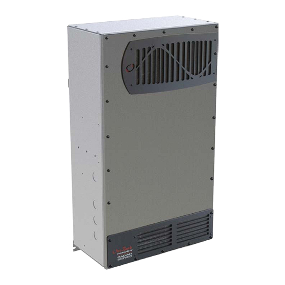
Introduction Figure Radian Series Inverter/Charger GS7048E 7000 watts (7 kW) continuous power at 48 Vdc 16.3 kVA peak surge capacity Modular internal design allows low idle consumption and high efficiency at high or low power operation GS3548E 3500 watts (3.5 kW) continuous power at 48 Vdc... -
Page 10: Inverter Controls
This is often more efficient than attempting to manually program each setting in each inverter. Affected fields include system type, battery charging, and AC source configuration. NOTE: Model GS7048E can only be used with MATE3 firmware revision 002.010.xxx or higher. Model GS3548E can only be used with MATE3 firmware revision 002.017.xxx or higher. -
Page 11: Commissioning
Commissioning Functional Test WARNING: Shock Hazard and Equipment Damage It is necessary to remove the inverter cover to perform these tests. The components are close together and carry hazardous voltages. Use appropriate care to avoid the risk of electric shock or equipment damage. Pre-startup Procedures 1. -
Page 12: Figure 3 Ac Test Points
Commissioning Metal pads are located at these locations. In commissioning, AC voltages can be measured at this series of test points. Figure 3 AC Test Points 4. Using a DVM or voltmeter, verify 230 Vac (or appropriate voltage) between the “L” and “N” OUT terminals. -
Page 13: Powering Down
Commissioning 5. Using the system display, temporarily bring each slave out of Silent mode by raising the Power Save Level of the master. (See page 39.) As each slave is activated, it will click and create an audible hum. Confirm that the system display shows no fault messages. -
Page 14: Firmware Updates
Commissioning Firmware Updates IMPORTANT: All inverters will shut down during firmware updates. If loads need to be run while updating the firmware, bypass the inverter with a maintenance bypass switch. Communication cables must remain connected and DC power must remain on. Interrupted communication will cause the update to fail and the inverter(s) may not work afterward. -
Page 15: Operation
Operation Inverter Functionality The inverter is capable of being used for many applications. Some of the inverter’s operations occur automatically. Others are conditional or must be enabled manually before they will operate. Most of the inverter’s individual operations and functions can be programmed using the system display. -
Page 16: Generator
Operation accept grid power. The opposite is also true. However, if using the Gen Alert or AGS functions, the generator must use the Gen terminals. See page 43 (Gen Alert) and page 47 (AGS).) When multiple inverters are stacked together in parallel, the master inverter’s input mode is imposed on all slaves. -
Page 17: Grid Tied
Operation input. The Gen Input AC Limit sets the maximum draw for the Gen input. The Support function takes effect if the AC demand on either input exceeds the AC Limit setting. BENEFITS: Large inverter loads can be powered while staying connected to the AC input, even if the input is limited. ... - Page 18 Operation The grid-interactive function is integrally tied with Offset operation and with the battery charger. See pages 35 and 27 for more information on these items. BENEFITS: Excess power is returned to the utility grid. The inverter will offset the loads with excess renewable energy if it is available from the batteries. ...
-
Page 19: Ups
Operation ∼ If the inverter stops selling or disconnects due to Grid Interface Protection, the MATE3 will show the reason. Sell Status messages are listed on page 61. Disconnect messages are listed on page 60. Often these messages will be the same. ∼... -
Page 20: Backup
Operation Backup Failure The Backup mode is intended for systems that have utility grid available as the primary AC source. This source will pass through the Radian inverter’s transfer circuit and will power the loads unless utility power is lost. If utility grid power is lost, then the Radian inverter will supply energy to the loads from the battery bank. -
Page 21: Grid Zero
Operation Mini Grid mode is also incompatible with the Grid Use Time and Load Grid Transfer functions of the MATE3 system display. These functions do not have similar priorities to Mini Grid or HBX, but they do control the inverter’s connection and disconnection with the grid. Mini Grid should not be used with these functions. When deciding whether to use Mini Grid mode or HBX, the user should consider the aspects of each. - Page 22 Operation The inverter remains connected to the utility grid in case the grid is needed. If large loads require the use of grid power, no transfer is necessary to support the loads. NOTES If the renewable energy source is not greater than the size of the inverter loads, this mode will not work well ...
-
Page 23: Table 1 Summary Of Input Modes
Operation Table 1 Summary of Input Modes Mode Summary Benefits Cautions Intended Charger Generator Accepts power Can use AC that may be Will pass irregular or Source: Performs three-stage unusable in other modes from an low-quality power to Generator charge and goes irregular or... -
Page 24: Description Of Inverter Operations
The inverter’s design uses transformers and high-frequency H-Bridge FET modules to achieve the required high-wattage output. In the GS7048E, the dual design allows half the inverter to shut down for lower idle consumption when not in use. -
Page 25: Ac Frequency
Operation Low Battery Cut-In: The recovery point from Low Battery Cut-Out. When the DC voltage rises above this point for 10 minutes, the error will clear and the inverter will resume functioning. This item is adjustable. ∼ Connecting an AC source for the Radian to charge the batteries will also clear a low battery error. Output Voltage: The AC output voltage can be adjusted. -
Page 26: Input
Operation NOTE: Due to load characteristics, these increments are only approximate and may not function exactly as listed. The pulse duration and the delay both have a time period that is measured in AC cycles. These two items and the load detection threshold are adjustable. Search mode may not be useful in larger systems with loads that require continuous power (e.g., clocks, ... -
Page 27: Ac Source Acceptance
Operation The AC input current is used to power both loads and battery charging. The combined amount should not exceed the size of the AC overcurrent device or AC source. These devices should be sized appropriately during planning and installation of the inverter system. If multiple parallel inverters are installed with an AC source of limited amperage, the total combined ... -
Page 28: Generator Input
Operation functions, all of which are operated by the MATE3 system display. (See page 47.) Another example is the MATE3’s AC INPUT hot key menu, which can order all inverters to disconnect when set to Drop. Generator Input A generator should be sized to provide enough power for all inverters, both for loads and for battery charging. -
Page 29: Battery Chargin
Radian inverters are installed, divide the total current by the number of inverters and program each with the resulting number. Table 2 Charge Currents for Radian Models Model Maximum DC Output (sent to battery) Maximum AC Input (used from source) GS7048E 100 Adc 30 Aac GS3548E 50 Adc 15 Aac Charge Cycle The inverter uses a “three-stage”... -
Page 30: Charging Graphs
Operation charging to a new voltage setting. A square indicates that the inverter has reached the setting (a horizontal dotted line). A triangle indicates that the inverter has stopped charging and is no longer using the previous set point. (The charging may have stopped for any of several reasons.) The battery voltage must drop to one of several low set points before the inverter resumes charging. -
Page 31: Charging Steps
Operation Charging Steps The following items describe the operation and intended use for each individual charging step as shown in the graphs. Note that some charging cycles may not follow this exact sequence. These include cycles which were previously interrupted, and also customized charging. Each step describes how to defeat or customize the step if specialized charging is required. - Page 32 Operation period whenever the battery voltage decreases below this setting. (See page 31 for more information on how the timer works.) To skip this step: Setting Absorb Time to a very short duration will cause the charger to spend minimal time in Absorption once the Bulk stage is complete. Setting Absorb Time to zero will cause the charger to skip both the Bulk and Absorption stages and proceed directly to Float.
-
Page 33: New Charging Cycle
Operation above that level. Often the timer will expire before the bulk and absorption stages are complete. If this happens, the charger will not enter Float but will go directly to Silent. The charger only spends time in Float stage if the timer is still running. Time limit: Float Time setting. -
Page 34: Figure 6 Repeated Charging Cycles
Operation Cycle 1 Cycle 2 Cycle 3 Cycle 4 Voltage AC Loss AC Loss AC Loss Absorption Absorption (c.v.) (c.v.) Absorption (c.v.) Absorption Set Point Float Float Bulk Bulk (c.c.) (c.c.) (c.c.) (c.c.) Float Set Point Silent Float Float Timer Timer (c.v.) (c.v.) -
Page 35: Equalization
Operation Equalization Equalization is a controlled overcharge that is part of regular battery maintenance. Equalization brings the batteries to a much higher voltage than usual and maintains this high voltage for a period of time. This has the result of removing inert compounds from the battery plates, and reducing stratification in the electrolyte. - Page 36 Operation If installed in a multiple-inverter system, only a single RTS is necessary. It must be plugged into the master inverter and will automatically control the charging of all slaves and all charge controllers. When charging, an inverter system with an RTS will increase or decrease the charge voltage by 5 mV per degree Celsius per battery cell.
-
Page 37: Offset
Operation Offset This operation is designed to use excess battery energy to power the loads when an AC source is present. This allows the system to take advantage of renewable energy sources, in effect “offsetting” dependence on the AC source. A renewable energy source will raise the battery voltage as it charges the batteries. -
Page 38: Multiple-Inverter Installations (Stacking)
Stacking allows all units to work together as one system. The GS7048E and GS3548E models can stack up to ten units in parallel for increased capacity. For three-phase output, up to nine models can be stacked, three per phase. -
Page 39: Parallel Stacking (Dual-Stack And Larger)
Operation the following message: An inverter firmware mismatch has been detected. Inverters X, Y, Z are disabled. Visit www.outbackpower.com for current inverter firmware. Installing multiple inverters without stacking them (or stacking them incorrectly) will result in similar errors and shutdown. Although stacking allows greater capacity, the loads, wiring, and ... -
Page 40: Three-Phase Stacking (Three Inverters)
Operation Three-Phase Stacking (Three Inverters) In three-phase stacking, inverters are stacked to create three AC outputs in a wye configuration. The three outputs operate independently of each other. Each can run in independent Search mode if desired, although this does not normally occur when three-phase loads are connected. Each output is 120°... -
Page 41: Power Save
Power Save functionality is different between Radian models. The Radian GS3548E contains only one 4kW module. Activating one module is the same as activating the full inverter. The GS7048E contains two modules and operates differently. Do not confuse the behavior of each. See Figure 12 and Figure 13 for differences. -
Page 42: Figure 12 Gs3548E Power Save Priority
Operation depending on the inverter’s stacking designation. Master Power Save Level appears on an inverter which is set as master (the default setting). In a stacked system, this selection should only appear on the inverter using Port 1 of the communications manager. The range of rank numbers is 0 to 31. -
Page 43: Figure 13 Gs7048E Power Save Priority
2.5 kW. Figure 13 shows a system of four GS7048E inverters (the master and three slaves) in a parallel system with a common load bus. The labels at the top indicate the ranking of each unit. The notations at the bottom show how the units are activated in sequence as loads of approximately 2.5 kW are applied. -
Page 44: Table 4 Changing Master Power Save Levels (Gs7048E)
The last line of the table shows the master increased to 3, which is the same as the rank of the highest slave. However, this only activates the first of the three slaves. The master would need to be set to rank 7 to activate all slaves. Table 4 Changing Master Power Save Levels (GS7048E) Master Slave 1 Slave 2... -
Page 45: Auxiliary Terminals
Operation Auxiliary Terminals The Radian inverter has two sets of terminals which can respond to different criteria and control many operations. The 12V AUX terminals provide a 12 Vdc output that can deliver up to 0.7 Adc to control external loads. The RELAY AUX terminals are “dry” relay contacts rated up to 10 amps (at 250 Vac or 30 Vdc). - Page 46 Operation examples are illustrated in the Radian Series Inverter/Charger Installation Manual. ∼ The AUX output will activate to start the generator when the battery voltage falls to a low set point for a settable delay. The AUX output is deactivated, shutting off the generator, once the battery voltage rises to a high voltage setting for a settable delay period.
- Page 47 Operation GT Limits activates the AUX output as an alert that the utility grid does not meet Grid Interface Protection parameters for the grid-interactive function (see page 15). It can activate a light or alarm to show that the grid-interactive function has shut down and that there may be problems with the grid.
-
Page 48: Table 5 Aux Mode Functions
Operation Table 5 Aux Mode Functions Triggers Settable Name Purpose Points Start Stop Load Operates designated loads High Vdc Low Vdc Low & high Vdc Shed normally; turns off loads in High temp On & Off delay ... -
Page 49: System Display-Based Functions
Operation System Display-Based Functions A system display such as the OutBack MATE3 can provide functions not available in the inverter. These functions are briefly described to provide a better idea of overall system capabilities. The system display must be present for these functions to operate. If a function is set up (or already in operation) but the system display is removed, the function will not operate. -
Page 50: Grid Use Time
Operation This mode has similar priorities to the Mini Grid input mode contained within the Radian inverter. Either mode may achieve similar results, but they are not identical. See page 18 for the advantages and disadvantages of each mode. Grid Use Time The inverter system is capable of connecting to, or disconnecting from, the utility grid based on time of day. -
Page 51: Metering
Metering MATE3 Screens The MATE3 system display can monitor the GS inverter and other networked OutBack devices. From the MATE3 Home screen, the Inverter “soft” key accesses the screens for monitoring the inverter. (See the MATE3 owner’s manual for more information.) Inverter Soft Key Figure 14 Home Screen... -
Page 52: Battery Screen
Metering Charge displays the kilowatts and AC amperage consumed for the inverter to charge the battery bank. This line also shows the present charging stage. Load displays kilowatts and AC amperage consumed by devices on the inverter’s output. It can be the same ... -
Page 53: Troubleshooting
Troubleshooting Basic Troubleshooting Table 6 is organized in order of common symptoms, with a series of possible causes. Each cause also shows possible troubleshooting remedies, including system display checks where appropriate. Metal pads are located at these locations. In troubleshooting, AC voltages can be measured at this series of test points. - Page 54 Troubleshooting Table 6 Troubleshooting Symptom Possible Cause Possible Remedy One or more Unit is slave and is in Power MATE3 system display only: Check Power Save levels in inverters will not the Inverter Stacking menu and test with loads. Determine if the Save mode.
- Page 55 Troubleshooting Table 6 Troubleshooting Symptom Possible Cause Possible Remedy Charge complete or nearly Check the DC voltage and charging stage using the MATE3, if complete. present. Confirm with DC voltmeter. MATE3’s DC meter reads Check the DC voltage on the inverter’s DC terminals. If different significantly higher than actual from the MATE3 reading, the inverter could be damaged.
- Page 56 Troubleshooting Table 6 Troubleshooting Symptom Possible Cause Possible Remedy Grid-tied function has been MATE3 system display only: Check the Grid-Tie Enable setting in manually disabled. the Grid-Tie Sell menu. Confirm it is set to Y. Grid Tied mode not in use on MATE3 system display only: Check the Inverter part of the Settings menu to see if Grid Tied mode is in use.
- Page 57 Troubleshooting Table 6 Troubleshooting Symptom Possible Cause Possible Remedy Inverter’s output has been Disconnect the wires from the inverter’s AC input or AC output connected to its input. Voltage terminals, or both. If the problem immediately disappears, it is an shifts are the result of trying to external wiring issue.
-
Page 58: Module Select
The GS7048E can be directed to use a single, specified module (left or right), or it can be directed to turn on both modules continuously. This procedure should only be performed if directed by OutBack Technical Support (see inside the front cover of this manual). -
Page 59: Error Messages
Troubleshooting Error Messages An error is caused by a critical fault. In most cases when this occurs, the unit will shut down. The MATE3 system display will show an event and a specific error message. This screen is viewed using the MATE3 Home screen’s soft keys. -
Page 60: Warning Messages
Troubleshooting Warning Messages A warning message is caused by a non-critical fault. When this occurs, the unit will not shut down, but the MATE3 system display will show an event and a specific warning message. This screen is viewed using the MATE3 Home screen’s soft keys. (See the MATE3 manual for more instructions.) One or more messages will display Y (yes). -
Page 61: Temperature Events
Troubleshooting Table 8 Warning Troubleshooting Message Definition Possible Remedy Fan Failure The inverter’s internal cooling fan is not Turn the battery disconnect off, and then on, to operating properly. Lack of cooling may result determine if the fan self-tests. After this test, in derated inverter output wattage. -
Page 62: Disconnect Messages
Troubleshooting Disconnect Messages Disconnect messages explain why the inverter has disconnected from an AC source after previously being connected. The unit returns to inverting mode if turned on. This screen is viewed using the AC INPUT hot key on the MATE3. One or more messages will display Y (yes). If a message says N (no), it is not the cause of the disconnection. -
Page 63: Sell Status
Troubleshooting Sell Status Sell Status messages describe conditions relating to the inverter’s grid-interactive mode. This screen is viewed using the MATE3 Home screen’s soft keys. (See the MATE3 manual for more instructions.) One or more messages will display Y (yes). If a message says N (no), it is not the cause of the disconnection. If the inverter has stopped selling or charging unexpectedly, this screen may identify the reason. - Page 64 Troubleshooting NOTES: 900-0145-01-01 Rev A...
-
Page 65: Specifications
Electrical Specifications NOTE: Items qualified with “default” can be manually changed using the system display. Table 12 Electrical Specifications for Radian Models Specification GS7048E GS3548E Continuous Output Power at 25°C 7000 VA 3500 VA Continuous AC Output Current at 25°C 30.4 Aac... -
Page 66: Mechanical Specifications
Specifications Table 12 Electrical Specifications for Radian Models Specification GS7048E GS3548E DC Input Maximum Current (surge) 406.5 Adc 203.3 Adc DC Input Maximum Current (short-circuit) 8975 Adc 4488 Adc Battery Charger Maximum AC Input 30 Aac at 230 Vac 15 Aac at 230 Vac... -
Page 67: Temperature Derating
All Radian inverters can deliver their full rated wattage at temperatures up to 25°C (77°F). The Radian maximum wattage is rated less in higher temperatures. Above 25°C, the GS7048E is derated by a factor of 70 VA for every increase of 1°C. The GS3548E is derated by 35 VA per 1°C. -
Page 68: Compliance
Specifications Compliance RoHS: per directive 2011/65/EU These inverter/charger models have grid-interactive functions. All models are tested to comply with certain limits for acceptable output voltage ranges, acceptable output frequency, total harmonic distortion (THD) and anti-islanding performance when the inverter exports power to a utility source. The OutBack inverter/charger models listed in this document are validated through compliance testing. -
Page 69: Firmware Revision
Specifications Firmware Revision This manual applies to inverter models GS7048E and GS3548E with Revision 001.005.xxx or higher. Updates to the Radian’s firmware are periodically available. These can be downloaded from the OutBack website www.outbackpower.com. See page 12. Default Settings and Ranges NOTE: Some items are retained at the present setting even when the inverter is reset to factory defaults. - Page 70 Specifications Table 16 Radian Inverter Settings Field Item Default Minimum Maximum Output Voltage 230 Vac 200 Vac 260 Vac AC Output AC Coupled Mode This selection is inoperative Cut-Out Voltage 42.0 Vdc 36.0 Vdc 48.0 Vdc Low Battery Cut-In Voltage 50.0 Vdc 40.0 Vdc 56.0 Vdc...
- Page 71 Grid-Tie Enable Y or N Grid-Tie Sell Sell Voltage 52.0 Vdc 44.0 Vdc 64.0 Vdc Auto Auto, Left, Right, Both GS7048E Module Control Module Control GS3548E Left Auto, Left, Right, Both Grid AC Input Voltage 0 Vac –7 Vac 7 Vac...
-
Page 72: Definitions
Specifications Definitions The following is a list of initials, terms, and definitions used in conjunction with this product. Table 17 Terms and Definitions Term Definition 12V AUX Auxiliary connection that supplies 12 Vdc to control external devices Alternating Current; refers to voltage produced by the inverter, utility grid, or generator Advanced Generator Start Direct Current;... -
Page 73: Index
Index Silent .................. 30 Steps ................29, 31 Commissioning ..............9 12V AUX ................. 43 Cool Fan .................. 44 Absorption Stage ..............29 Default Settings ..............67 AC Input ................. 24 Definitions ................70 AC Source Acceptance ............. 25 Design ..................22 AC Test Points ............... - Page 74 Index GT Limits ................45 Regulatory ................65 Relay AUX ................43 High Battery Cut-Out ............22 Remote System Display ............ 70 High Battery Transfer (HBX) ........18, 47 Remote Temperature Sensor (RTS) ....... 33, 70 IEC ..................... 70 Safety ..................5 Important Symbol ..............
- Page 75 Index Vent Fan Control ..............44 Warning Symbol ..............5 Warnings ................58 Website ................12, 67 900-0145-01-01 Rev A...
- Page 76 YOUR OUTBACK POWER DISTRIBUTOR SOLIGENT 800-967-6917 www.soligent.net Masters of the Off-Grid.™ First Choice for the New Grid. Corporate Headquarters European Office 17825 – 59 Avenue N.E. Hansastrasse 8 Suite B D-91126 Arlington, WA 98223 USA Schwabach, Germany +1.360.435.6030 +49.9122.79889.0 900-0145-01-01 Rev A...
Need help?
Do you have a question about the GS7048E and is the answer not in the manual?
Questions and answers