Table of Contents
Advertisement
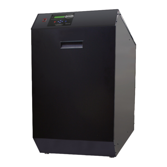
Mod Con VWH
INSTALLATION
START-UP
MAINTENANCE
PARTS
VWH Models
500 / 850
LP / HL / LPHL
THIS MANUAL IS FOR USE WITH MOD CON BOILERS MANUFACTURED AFTER
DECEMBER 1, 2012
Heat Exchanger Bears the ASME "H" Stamp
This manual must only be used by a qualified heating installer/service technician. Read all instructions in this manual before installing.
Perform steps in the order given. Failure to comply could result in substantial property damage, severe personal injury, or death.
Improper installation, adjustment, alteration, service, or maintenance could void product warranty and cause property damage, personal
injury, or death.
NOTICE: HTP reserves the right to make product changes or updates without notice and will not be held liable for typographical errors
in literature.
The surfaces of these products contacted by consumable water contain less than 0.25% lead by weight, as required by the Safe
Drinking Water Act, Section 1417.
NOTE TO CONSUMER: PLEASE KEEP ALL INSTRUCTIONS FOR FUTURE REFERENCE.
120 Braley Rd. P.O. Box 429
East Freetown, MA 02717-0429
www.htproducts.com
LP- 446 REV. 9.3.14
Advertisement
Table of Contents

Subscribe to Our Youtube Channel
Related Manuals for HTP 500 LP


Summary of Contents for HTP 500 LP
- Page 1 Improper installation, adjustment, alteration, service, or maintenance could void product warranty and cause property damage, personal injury, or death. NOTICE: HTP reserves the right to make product changes or updates without notice and will not be held liable for typographical errors in literature.
- Page 2 IF THE INFORMATION IN THIS MANUAL IS NOT FOLLOWED EXACTLY, A FIRE OR EXPLOSION MAY RESULT, CAUSING PROPERTY DAMAGE, PERSONAL INJURY, OR LOSS OF LIFE. DO NOT STORE GASOLINE OR OTHER FLAMMABLE VAPORS AND LIQUIDS IN THE VICINITY OF THIS OR ANY OTHER APPLIANCE. WHAT TO DO IF YOU SMELL GAS ...
-
Page 3: For The Installer
In some circumstances, the property owner or his/her agent assumes the role, and at government installations, the commanding officer or departmental official may be the AHJ. NOTE: HTP, Inc. reserves the right to modify product technical specifications and components without prior notice. FOR THE INSTALLER This manual must only be used by a qualified heating installer/service technician. -
Page 4: Table Of Contents
The latest version of the National Electrical Code, NFPA No. 70. NOTE: The gas manifold and controls met safe lighting and other performance criteria when the boiler underwent tests specified in ANSI Z21.13 – latest edition. NOTICE The CSD-1 ASME Code, Section CW-400 requires that hot water heating and supply boilers have a) a UL 353 temperature control device, b) at least one (1) temperature-actuated control to shut off the fuel supply when system water reaches a preset operating temperature, c) a high temperature limit control that prevents the water temperature from exceeding the maximum allowable temperature by causing a safety shutdown and lockout, and d) its own sensing element and operating switch. - Page 5 H. PIPING DIAGRAMS .................................. 21 PART 5 – VENTING, COMBUSTION AIR AND CONDENSATE REMOVAL................27 A. GENERAL ....................................27 B. APPROVED MATERIALS FOR EXHAUST VENT AND INTAKE PIPE ..................28 C. REQUIREMENTS FOR INSTALLATION IN CANADA ......................29 D. EXHAUST VENT AND INTAKE PIPE LOCATION........................30 E.
-
Page 6: Part 1 - General Safety Information
BOILER START-UP REPORT ..............................75 MAINTENANCE REPORT ................................. 75 MAINTENANCE NOTES .................................. 79 HTP CUSTOMER INSTALLATION RECORD FORM........................80 PART 1 – GENERAL SAFETY INFORMATION A. PRECAUTIONS This appliance is for indoor installations only. Clearance to combustible materials: 0” top, bottom, sides and back. Front must have room for service, 24”... -
Page 7: Improper Combustion
FAILURE TO PIPE THE UNIT PROPERLY WILL VOID THE WARRANTY. NOTE: Damages resulting from incorrect installation or from use of products not approved by HTP, Inc. ARE NOT covered by warranty. PART 2 – BEFORE YOU START VWH units must be connected to a storage tank. -
Page 8: What's In The Box
Mod Con 500 VWH Outlet Recovery Gallons Per First Hour Rating With 80 First Hour Rating With 119 First Hour Rating With 175 Temperature Hour Gallon Gallon Gallon 1,410 1,470 1,499 1,535 1,128 1,188 1,217 1,253 1,000 1,029 1,065 Table 1 – Mod Con 500 VWH Recovery Ratings with Storage Tanks and 40 F Inlet Temperature Mod Con 850 VWH Outlet... -
Page 9: How Boiler Operates
Pressure Relief Valve Intake PVC Tee with Screens Exhaust PVC Coupling with Screens Supply and Return Thermistors Flow Switch and Fitting Wiring Harness System/Pipe Sensor Installation Manual Warranty CSD-1 Form ... -
Page 10: Optional Equipment
Indirect Tank Sensor (optional) – Monitors storage tank temperature. C. OPTIONAL EQUIPMENT Below is a list of optional equipment available from HTP: Indirect Tank Sensor (Part # 7250P-325) ... -
Page 11: Leveling And Dimensions
2. Check for nearby connections to: System water piping Venting connections Gas supply piping Electrical power Condensate drain 3. Check area around boiler. Remove any combustible materials, gasoline, and other flammable liquids. Failure to keep boiler area clear and free of combustible materials, liquids, and vapors can result in substantial property damage, severe personal injury, or death. - Page 12 Figure 2 – Dimensions and Specifications LP- 446 REV. 9.3.14...
-
Page 13: Clearances For Service Access
C. CLEARANCES FOR SERVICE ACCESS See Figure 3 for recommended service clearances. If you do not provide the minimum clearances shown, it might not be possible to service the boiler without removing it from the space. Space must be provided with combustion/ventilation air openings correctly sized for all appliances located in the same space as the boiler. -
Page 14: Removing A Boiler From A Common Vent System
PRODUCTS TO AVOID AREAS LIKELY TO HAVE CONTAMINANTS Spray cans containing fluorocarbons Dry cleaning/laundry areas and establishments Permanent wave solutions Swimming pools Chlorinated waxes/cleaners Metal fabrication plants Chlorine-based swimming pool chemicals Beauty shops Calcium chloride used for thawing Refrigeration repair shops Sodium chloride used for water softening Photo processing plants Refrigerant leaks... -
Page 15: Uncrating And Moving Boiler
Plumbing of this product should only be done by a qualified, licensed plumber in accordance with all local plumbing codes. The boiler is designed to be connected to a storage tank to supply domestic hot water. HTP offers 80/119/175 gallon size storage tanks in either Stainless Steel or Glass lined construction. -
Page 16: System Water Piping Methods
The boiler is designed to be connected to a storage tank to supply domestic hot water. HTP offers storage tanks that are 80/119/175 gallon size storage tanks constructed in either stainless steel or glass-lined construction. These storage tanks connect directly to the boiler supply and return connections. -
Page 17: Scalding
the system, you must install an additional tee for a suitable potable hot water expansion tank. Connect the Storage tank return line to the return connection located on the Mod Con VWH (shown in Piping Diagrams). Then connect your hot water outlet located on the storage tank to your hot water plumbing lines. - Page 18 Table 7 – Multiple Boiler Manifold Piping The table below represents the various system design temperature rise through the Mod Con along with the respective flow and friction loss which will aid in circulator selection. SYSTEM TEMPERATURE RISE CHART ∆t ∆t ∆t MODEL...
-
Page 19: Water Chemistry
Table 9 – Mod Con Heat Exchanger Pressure Drop G. WATER CHEMISTRY Chemical imbalance of your water can cause severe damage to your water heater and associated equipment, and may also affect efficiency. You may have to have your water quality professionally analyzed to determine whether you need to install a water softener. It is important that the water chemistry on both the domestic hot water and central heating sides are checked before installing the heater, as water quality will affect the reliability of the system. -
Page 20: Lp- 446 Rev
Water with a high TDS concentration will greatly accelerate lime and scale formation in the hot water system. Most high TDS concentrations precipitate out of the water when heated. This can generate a scale accumulation on the heat transfer surface that will greatly reduce the service life of a water heater. -
Page 21: Piping Diagrams
H. PIPING DIAGRAMS Figure 6 LP- 446 REV. 9.3.14... - Page 22 Figure 7 NOTES: 1. This drawing is meant to demonstrate system piping concept only. Installer is responsible for all equipment and detailing required by local codes. 2. Boiler circulator(s) must be rated for open loop applications. Do not use cast-iron circulators. 3.
- Page 23 Figure 8 NOTES: 1. This drawing is meant to demonstrate system piping concept only. Installer is responsible for all equipment and detailing required by local codes. 2. Boiler circulator(s) must be rated for open loop applications. Do not use cast-iron circulators. 3.
- Page 24 Figure 9 NOTES: 1. This drawing is meant to demonstrate system piping concept only. Installer is responsible for all equipment and detailing required by local codes. 2. Boiler circulator(s) must be rated for open loop applications. Do not use cast-iron circulators. 3.
- Page 25 Figure 10 NOTES: 1. This drawing is meant to demonstrate system piping concept only. Installer is responsible for all equipment and detailing required by local codes. 2. Boiler circulator(s) must be rated for open loop applications. Do not use cast-iron circulators. 3.
- Page 26 Figure 11 NOTES: 1. This drawing is meant to demonstrate system piping concept only. Installer is responsible for all equipment and detailing required by local codes. 2. Boiler circulator(s) must be rated for open loop applications. Do not use cast-iron circulators. 3.
-
Page 27: Part 5 - Venting, Combustion Air And Condensate Removal
Figure 12 NOTES: 1. This drawing is meant to demonstrate system piping concept only. Installer is responsible for all equipment and detailing required by local codes. 2. Boiler circulator(s) must be rated for open loop applications. Do not use cast-iron circulators. 3. -
Page 28: Approved Materials For Exhaust Vent And Intake Pipe
1. Installation should be made in accordance with the regulations of the Authority Having Jurisdiction, local code authorities, and utility companies which pertain to this type of water heating equipment. 2. Install the venting system in accordance with these instructions and with the National Fuel Gas Code, ANSI Z223.1/NFPA 54, CAN/CGA B149, and/or applicable provisions of local building codes. -
Page 29: Requirements For Installation In Canada
When installing AL29-4C vent piping, install a PVC-to-stainless adapter at the boiler vent connection, and at the termination when using an HTP PVC termination kit. DO NOT mix AL-29-4C piping from different manufacturers unless using adapters specifically designed for the purpose by the manufacturer. -
Page 30: Exhaust Vent And Intake Pipe Location
Figure 13 D. EXHAUST VENT AND INTAKE PIPE LOCATION You must insert the provided exhaust and intake screens at your vent termination to prevent blockage caused by debris or birds. NOTE: SEE ADDITIONAL REQUIREMENTS FOR MASSACHUSETTS IN THE BACK OF THIS MANUAL. 1. - Page 31 Condensate from the boiler is slightly acidic with a pH of 3.2 - 4.5. To avoid long term damage to the drainage system and to meet local code requirements, HTP recommends neutralizing the condensate with a Condensate Neutralizer Kit (Part # 7350P-611). The neutralizer kit connects to the drain system and contains marble chips that neutralize the pH level of the water vapor.
- Page 32 Figure 14 – Condensate Piping NOTE: Blow water into the condensate collector to remove any foreign matter that may block the line. NOTES: 1. Condensate line must be pitched at least 1/4" per foot to properly drain. If this cannot be done, or a very long length of condensate hose is used, you must increase the condensate line to a minimum of 1”...
-
Page 33: Exhaust Vent And Intake Pipe Sizing
3. NEVER install condensate lines outside. It is very important that the condensate line is not exposed to freezing temperatures or any type of blockage. Damages due to frozen or blocked condensate lines ARE NOT covered by warranty. 4. Support of the condensate line may be necessary to avoid blockage of the condensate flow. The condensate line must remain unobstructed, allowing free flow of condensate. -
Page 34: Boiler Removal From A Common Vent System
NOTE: For Canadian Installations, it is required that Non Metallic Vent Installations conform to ULC S636. Where plastic venting is not allowed, HTP recommends AL294C Stainless Steel Venting be used for Exhaust venting installations and “B” vent for intake air. -
Page 35: Sidewall Venting Diagrams
I. SIDEWALL VENTING DIAGRAMS Figure 16 – Sidewall Venting Diagrams All vent pipes must be glued, properly supported, and the exhaust must be pitched a minimum of ¼” per foot back to the boiler to allow drainage of condensate. Exhaust connection insertion depth should be a minimum of 2 ½” for 500 models and 3” for 850. When placing support brackets on vent piping, the first bracket must be within 1’... - Page 36 Figure 17 – Sidewall Venting with Tee and Coupling All vent pipes must be glued, properly supported, and the exhaust must be pitched a minimum of ¼” per foot back to the boiler to allow drainage of condensate. Exhaust connection insertion depth should be a minimum of 2 ½” for 500 models and 3” for 850. When placing support brackets on vent piping, the first bracket must be within 1’...
-
Page 37: Vertical Venting Diagrams
J. VERTICAL VENTING DIAGRAMS Figure 18 – Two Pipe Roof Venting with Tee and Coupling All vent pipes must be glued, properly supported, and the exhaust must be pitched a minimum of ¼” per foot back to the boiler to allow drainage of condensate. - Page 38 Figure 19 – Horizontal Venting - NOTE: Drawing is meant to demonstrate system venting ONLY. NOTES: A. For every 1” of overhang, the exhaust vent must be located 1” vertical below overhang (overhang means top of building structure and not two adjacent walls [corner of building]). B.
- Page 39 Figure 20 – Roof and Sidewall Venting with Stainless Steel All vent pipes must be glued, properly supported, and the exhaust must be pitched a minimum of ¼” per foot back to the boiler to allow drainage of condensate. Exhaust connection insertion depth should be a minimum of 2 ½” for 500 models and 3” for 850. When placing support brackets on vent piping, the first bracket must be within 1’...
-
Page 40: Room Air, Indoor Combustion, And Ventilation Air Installation Requirements
K. ROOM AIR, INDOOR COMBUSTION, AND VENTILATION AIR INSTALLATION REQUIREMENTS When using an indoor combustion air installation, the mechanical room MUST be provided with properly sized openings, and/or be of sufficient volume to assure adequate combustion air and proper ventilation for all gas fired appliances in the mechanical room to assure adequate combustion air and proper ventilation. -
Page 41: Part 6 - Gas Piping
Under no circumstances should the mechanical room ever be under negative pressure. Particular care should be taken where exhaust fans, attic fans, clothes dryers, compressors, air handling units, etc., may take away air from the unit. Failure to follow these instructions could result in property damage or personal injury. -
Page 42: Gas Piping
Do not attempt to support the weight of gas piping with the boiler or its accessories. The gas valve and blower will not support the weight of the piping. Failure to follow this warning could result in substantial property damage, severe personal injury, or death. The gas connection on the boiler is 1-1/2”... -
Page 43: Check Inlet Gas Pressure
NATURAL GAS SUPPLY PIPING CAPACITY CHART (0.6 specific gravity gas; 0.5” WC pressure drop) *Schedule 40 iron pipe size in nominal inches MODEL 1 BOILER 2 BOILERS 3 BOILERS 4 BOILERS 5 BOILERS 6 BOILERS 7 BOILERS 8 BOILERS CUBIC FT. HR. 1000 1500 2000... -
Page 44: Gas Valve
E. GAS VALVE Figure 26 – Mod Con 500 Gas Valve LP- 446 REV. 9.3.14... - Page 45 Figure 27 – Mod Con 850 Gas Valve Do not do a gas conversion on this boiler without an officially approved conversion kit and instructions supplied by HTP. Failure to use a conversion kit when converting the boiler to fire on Natural or LP gas will result in extremely dangerous burner operation, leading to fire, explosion, severe injury or death.
-
Page 46: Part 7 - Field Wiring
Adjustments to the throttle screw or offset may only be made by a qualified gas technician using a calibrated combustion analyzer capable of measuring CO and CO. Failure to follow this instruction could result in fire, explosion, property damage, severe personal injury, or death. -
Page 47: Line Voltage Wiring
each tank and wire them in series to provide temperature control of the tanks. (See Piping Diagrams in Part 4 for reference.) The control in the Mod Con VWH will read either the temperature of the tank sensor or the status of the aquastats, and cause the boiler to run until the water temperature of the tank(s) meets the desired set point. -
Page 48: Low Voltage Connections For Standard Boiler
Avoid running communication cables parallel and close to or against high voltage (120 volt or greater) wiring. HTP recommends that the maximum length of communication bus cables not exceed 200 feet. -
Page 49: Vwh Cascade Master Pump And Sensor Wiring
4. Route the communication cables through one of the knockouts in the cabinet. 5. Connect the boilers in a daisy chain configuration as shown below. It is best to wire the boilers using the shortest wire runs rather than trying to wire them in the order that they are addressed. The communication bus jacks on the customer connection panel are interchangeable so you can use either one or both in any order to connect the cable. - Page 50 2. If it is desired to have the boiler control the boiler pump, connect the boiler pump to the BOILER HOT, BOILER NEUT, and BOILER GND terminals. 3. Connect the system sensor to the terminals marked SYS SENSOR. 4. Do not connect anything to the OUTDOOR SENS or THERMOSTAT terminals. 5.
-
Page 51: Vwh Cascade Follower Pump And Sensor Wiring
N. VWH CASCADE FOLLOWER PUMP AND SENSOR WIRING 1. If it is desired to have the boiler control the boiler pump, connect the boiler pump to the BOILER HOT, BOILER NEUT, and BOILER GND terminals. 2. Connect the tank sensor(s) or return sensor to the terminals marked TANK SENSOR on the follower boiler addressed as 1. There are no connections to these terminals on other follower boilers in the system. - Page 52 Figure 33 – Mod Con Internal Connection Diagram – LP-428-K LP- 446 REV. 9.3.14...
-
Page 53: Part 8 - Start-Up Preparation
PART 8 – START-UP PREPARATION A. CHECK / CONTROL WATER CHEMISTRY Chemical imbalance of your water can cause severe damage to your heater and associated equipment, and may also affect efficiency. You may have to have your water quality professionally analyzed to determine whether you need to install a water softener. It is important that the water chemistry on both the domestic hot water and central heating sides are checked before installing the heater, as water quality will affect the reliability of the system. -
Page 54: Final Checks Before Starting Heater
If the condensate outlet on the appliance is lower than the drain, you must use a condensate removal pump, available from HTP (554200). This pump is equipped with two leads that can be connected to an alarm or another type of warning device to alert the user of a condensate overflow, which, if not corrected, could cause property damage. -
Page 55: Lockout Condition
recheck the bus every few seconds as long as it is powered up to update the status of the connected heaters. The control in the master heater processes all heat demands and dictates which of the follower heaters should light and what firing rate the followers should try to achieve. -
Page 56: Part 9 - Start-Up Procedure
f. Exit system menu. NOTE: The temperature set point of the follower must match the master heater set point in order for the system to operate properly. PART 9 – START-UP PROCEDURE FOR YOUR OWN SAFETY READ BEFORE OPERATING 1. This heater does not have pilot. It is equipped with an ignition device which automatically lights the burner. Do not try to light the burner by hand. -
Page 57: Operating Instructions
The ENTER key is also used to enable a function for editing. After the user navigates to the desired function, the user would hold down the ENTER key for one second. When the ENTER key is released, the function value will begin to blink. The function can now be changed using the ▼▲... -
Page 58: Programming The System Setting
Function: Adjusts the temperature measurement in F = Fahrenheit to C = Celsius (Default is Fahrenheit). TEMP DISPLAY C OR F Table 17 – Heater Setting Program Navigation Clock Settings (NOTE: The clock will reset if the heater is powered off for more than a week.) SCREEN DESCRIPTION Function: Changes the clock from 12 hour mode (8:45 PM) to 24 hour mode (20:45). - Page 59 Function 6 VWH Post Pump Time The heater pump has the ability to post purge energy from the heater to the tank after the set point has been POST PUMP TIME achieved. Please note that running the pump for a time greater than 5 minutes may cause tank energy to be 0 MINUTES released back to the heat exchanger.
-
Page 60: Resetting The Maintenance Schedule
Extra Heater Mode EXTRA HEATER MODE Allows for a non HTP heater to be controlled when the cascade output has risen above the percent of the cascade firing rate set in this parameter. Factory Default: Off (Range: 50% - 100%). -
Page 61: Part 10 - Start-Up Procedures For The Installer
TANK SET the tank or return line sensor (HTP 7250P-325) is displayed on the bottom line. If a mechanical aquastat is used in place of the recommended sensor, the second line will display ‘OFF’ in place of the temperature if the aquastat RET / TANK measures close to its set temperature, or ‘ON’... -
Page 62: Cascade Menu
Press the ▼ key once. This screen displays the fourth oldest lockout fault that occurred in the heater controller. The top line will FAULT HISTORY alternate between the words ‘FAULT HISTORY’ and the fault encountered. The bottom line displays the date 08/28/2009 Fr 5:19A and time the fault occurred. -
Page 63: Heater Test Mode
Press the ▼ key once. HEATER 2 This screen shows the current cascade power demand output on a per connected heater basis for heaters addressed as 2 and 3. HEATER 3 Press the ▼ key once. HEATER 4 This screen shows the current cascade power demand output on a per connected heater basis for heaters addressed as 4 and 5. -
Page 64: User Interface Display
When servicing or replacing any components of this heater, be certain that: The gas is off. All electrical power is disconnected. When servicing or replacing components that are in direct contact with heater water, be certain that: There is no pressure in the heater. - Page 65 Fault Code LOU 1. Check line voltage. It must be between 100 and 128 volts. 2. If available, connect PC, and using HTP service software check the 24v supply display in the lower left corner of the screen. The number displayed here must be greater than 128 and should be no greater than 250.
- Page 66 Fault Code F04 This display indicates that the flue temperature Inspect the flue sensor for physical damage or corrosion and sensor of the heater has failed. This is a replace it if necessary. Check the electrical connection to the flue serious safety issue.
- Page 67 Figure 34 Fault Code F10 1. Monitor the gas pressure to the unit while in operation. 2. Assure that the flame is stable when lit. 3. Check to see if the display readout changes from “GAS VALVE The flame was lost while the heater was firing 3 ON”...
- Page 68 Fault Code F16 1. Check flue system for obstructions. 2. Check proper communication between boilers. APS CLOSED Flapper valve stuck closed. 3. Check operation of flapper valve. 4. Check wiring between valve and controller. 5. Replace valve-flapper. Fault Code F20 The condensate trap is full.
-
Page 69: Part 12 - Maintenance
Supply Temperature Sensor (7250P-324) Outdoor Sensor (7250P-319) Heater Sensor (7250P-667) Indirect Sensor (7250P-325) Outside Temperature ( Resistance (ohms) Outside Temperature ( Resistance (ohms) 171800 32550 129800 25340 98930 19870 76020 15700 58880 12490 45950 10000 36130 8059 28600 6535 22800 5330 18300 4372... -
Page 70: Combustion Chamber Coil Cleaning Instructions For Heater
B. COMBUSTION CHAMBER COIL CLEANING INSTRUCTIONS FOR HEATER *Before beginning this procedure, you must have on hand the following items: a nylon, stainless steel, or brass brush (not steel) gloves and eye protection 1. Shut down the Heater by using the following steps: a. - Page 71 Figure 36 LP- 446 REV. 9.3.14...
- Page 72 Figure 37 LP- 446 REV. 9.3.14...
- Page 73 Figure 38 LP- 446 REV. 9.3.14...
- Page 74 Figure 39 LP- 446 REV. 9.3.14...
-
Page 75: Boiler Start-Up Report
BOILER START-UP REPORT LIGHT OFF ACTIVITIES DATE COMPLETED ________________ 1) Fill the Check all piping and gas connections, verify all are tight heating system Pressurize system (12 – 15 PSI) ____ PSI Add water to prime condensate cup Percentage of glycol in system (0-50%) ____% Verify near heater piping is properly supported 2) Check gas... - Page 76 The boiler requires minimal periodic maintenance under normal conditions. However, in unusually dirty or dusty conditions, periodic vacuuming of the cover to maintain visibility of the display and indicators is recommended. Periodic maintenance should be performed once a year by a qualified service technician to assure that all the equipment is operating safely and efficiently.
- Page 77 LP- 446 REV. 9.3.14...
- Page 78 LP- 446 REV. 9.3.14...
-
Page 79: Maintenance Notes
MAINTENANCE NOTES LP- 446 REV. 9.3.14... -
Page 80: Htp Customer Installation Record Form
HTP CUSTOMER INSTALLATION RECORD FORM The following form should be completed by the installer for you to keep as a record of the installation in case of a warranty claim. After reading the important notes at the bottom of the page, please also sign this document.
Need help?
Do you have a question about the 500 LP and is the answer not in the manual?
Questions and answers