SIGLENT SDM3055 User Manual
Siglent digital multimeter user manual
Hide thumbs
Also See for SDM3055:
- Quick start manual (9 pages) ,
- Quick start manual (28 pages) ,
- User manual (111 pages)

Subscribe to Our Youtube Channel
Related Manuals for SIGLENT SDM3055


Summary of Contents for SIGLENT SDM3055
- Page 1 User Manual SDM3055 Digital Multimeter UM06035-E02A 2014 SIGLENT TECHNOLOGIES CO., LTD...
- Page 2 SIGLENT TECHNOLOGIES CO., LTD. All rights reserved. Trademark Information SIGLENT is registered trademark of SIGLENT TECHNOLOGIES CO., LTD. Statement ● SIGLENT products are protected by patent laws in and outside of the P.R. China. ● SIGLENT reserves the rights to change the specification and price. ●...
-
Page 3: General Safety Summary
Do not operate with suspected failures If you suspect that the product is damaged, please contact SIGLENT’s qualified service personnel to inspect it. Any repair and adjustment to the product or replacing a component should be done by qualified personnel only. - Page 4 2. Sampling (HI Sense and LO Sense) terminal HI Sense and LO Sense are used for 4-wire Resistance measurement. Two protection limitations are defined: HI Sense-LO Sense protection limitation: 2000Vpk. LO Sense-LO Sense protection limitation: 2Vpk. SDM3055 Digital Multimeter...
- Page 5 SDM3055 is capable of making measurements with the HI and LO inputs connected to mains in such devices (up to 600VAC) or the branch outlet itself. However, the HI and LO terminals of SDM3055 can’t be connected to mains in permanently installed electrical devices such as the main circuit-breaker panels, sub-panel disconnected boxes and permanently wired motors.
-
Page 6: Safety Terms And Symbols
CAUTION indicates that a potential damage to the instrument or other property might occur. Symbols used on the instrument. Symbols may appear on the instrument. Hazardous Protective Earth Warning Test Chassis Voltage Ground Ground Ground SDM3055 Digital Multimeter... -
Page 7: Introduction Of Sdm3055
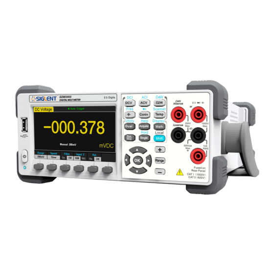
SDM3055 holds a 4.3 inch color TFT-LCD display screen. Its clear keyboard layout and operation hints make it easier and agility to use. Besides, it supports multi-interface such as USB Device & Host, LAN and GPIB (only for SDM3055A), which can meet users’... -
Page 8: Abstract
The manual mainly introduces corresponding information of operating the SDM3055 Digital Multimeter. It contains these chapters: Chapter 1 Quick Start Guide you to prepare the SDM3055 Digital Multimeter and know about the Front/Back panel and user interface. Chapter 2 Function and Operation Introduce the functions and operations of SDM3055 in details. -
Page 9: Table Of Contents
SIGLENT Content Copyright and Statement ................II General Safety Summary................II Safety Terms and Symbols ................V Introduction of SDM3055 ................VI Abstract ....................... VII Content ....................... VIII Chapter 1 Quick Start ................1 General Inspection ..................2 To adjust the Handle ................. 3 Front Panel .................... - Page 10 Application of the Analog Filter ............... 96 Chapter 5 General Troubleshooting............97 Chapter 6 Appendix ................. 98 Appendix A: Accessories ................ 98 Appendix B: Warranty summary ............. 99 Appendix C: Daily Maintenance and Cleaning ........100 Appendix D: Contact SIGLENT ............. 101 SDM3055 Digital Multimeter...
-
Page 11: Chapter 1 Quick Start
SIGLENT Chapter 1 Quick Start General Inspection Handle Adjustment The Front Panel The Back Panel To Connect Power Line User Interface To Use Safety Lock SDM3055 Digital Multimeter... -
Page 12: General Inspection
Damages of the instrument caused by the shipment will be compensated by the shipper or carrier. SIGLENT will not be responsible for the free repair or replacement. 2. Inspect the instrument. -
Page 13: To Adjust The Handle
SIGLENT To adjust the Handle Adjust the handle position of SDM3055 properly to place the instrument stably so that users can manipulate and observe the display better. Please grip the handle by the two sides and pull it outward. Then rotate the handle to the appropriate position. -
Page 14: Front Panel
SIGLENT Front Panel SDM3055 Digital Multimeter provides users with brief and clear front panel. These control buttons are group by logic and users only need choose corresponding buttons to carry out basic operations, as shown in Diagram 1-4. Diagram 1- 4 Front Panel Overview... -
Page 15: Back Panel
SIGLENT Back Panel SDM3055 Digital Multimeter’s Back Panel provides users with abundant interfaces, including USB Device、USB Host、LAN and GPIB(Only for SDM3055A), as shown in the following diagram. Diagram 1- 5 Back Panel Overview Power Socket Power Fuse AC Voltage Selector Inspection card interface USB Device(USBTMC)... -
Page 16: Power On
2. Connect the instrument to AC supply via power cord supplied by SIGLENT; 3. The power indicator light on the front panel will glitter slowly; 4. Press the power key on the front panel, the instrument will be started a few seconds later. SDM3055 Digital Multimeter... -
Page 17: User Interface
SIGLENT User Interface Single Display: Trigger Mode Main Display Function Reading Display Softkey Menu Measurement Range Unit Diagram 1- 6 Single Display Interface Dual-Display: Main Display Function Main Display Vice-display Diagram 1-7 User Interface SDM3055 Digital Multimeter... -
Page 18: Chapter 2 Function And Operation
Acquire Function or Help System Math Function or Display Function Run / Stop Single Trigger / Hold Measurement Function To Switch Functions or Return to Local Menu To Select Measurement Range SDM3055 Digital Multimeter... -
Page 19: To Select Measurement Range
Method 2: By softkeys on the measurement main interface as Diagram 2-2. Auto Range: Press 【Auto】 to choose Auto Range, meanwhile Manual Range is forbidden. Manual Range: Press【200mV】、【2V】、【20V】、【200V】or【1000V】 to choose required range manually. Auto Range is forbidden at this moment. SDM3055 Digital Multimeter... - Page 20 2kΩ, while the Diode is 2V. 6. Auto Range is not suitable for measuring current up to 10A. If the signal is used to I Terminal, users need to choose range manually. SDM3055 Digital Multimeter...
-
Page 21: To Select Measurement Speed
7. The reading resolution and measurement rate of the Frequency function are fixed 5.5 digit and “Slow” respectively. 8. The reading resolution and measurement rate of the Capacitance function are fixed at 5.5 digit and “Slow” respectively. SDM3055 Digital Multimeter... -
Page 22: Basic Measurement Functions
SIGLENT Basic Measurement Functions SDM3055 Digital Multimeters have following basic functions: To Measure DC Voltage To Measure AC Voltage To Measure DC Current To Measure AC Current To Measure 2/4-Wire Resistance To Measure Capacitance ... -
Page 23: To Measure Dc Voltage
Diagram 2- 4. Diagram 2- 4 DC Voltage Measurement Interface 2. Connect the red lead to terminal Input-HI and black lead to terminal Input-LO as the following diagram. Diagram 2- 5 Sketch Map for Measuring DC Voltage SDM3055 Digital Multimeter... - Page 24 7. Read measurement result. Select required measurement rate (reading rate) by pressing 【Speed】 and read the measurement result. 8. View history data. There are four types of way to view historical data: “Number”, “Bar Meter” ”Trend Chart” and “Histogram”. SDM3055 Digital Multimeter...
-
Page 25: To Measure Dc Current
Diagram 2- 6. Diagram 2- 6 DC Voltage Measurement Interface 2. Connect the red lead to terminal Input-I and black lead to terminal Input-LO as the following diagram. Diagram 2- 7 Sketch Map for Measuring DC Current SDM3055 Digital Multimeter... - Page 26 6. Read measurement result. Select required measurement rate (reading rate) by pressing【Speed】and read the measurement result. 7. View history data. There are four types of way to view historical data: “Number”, “Bar Meter” ”Trend Chart” and “Histogram”. SDM3055 Digital Multimeter...
-
Page 27: To Measure Ac Voltage
Diagram 2- 8. Diagram 2- 8 AC Voltage Measurement Interface 2. Connect the red lead to terminal Input-HI and black lead to terminal Input-LO as the following diagram. Diagram 2- 9 Sketch Map for Measuring AC Voltage SDM3055 Digital Multimeter... - Page 28 AC signal. Diagram 2- 10 Dual-display 6. View history data. There are four types of way to view historical data: “Number”, “Bar Meter” ”Trend Chart” and “Histogram”. SDM3055 Digital Multimeter...
-
Page 29: To Measure Ac Current
Diagram 2- 11. Diagram 2- 11 AC Voltage Measurement Interface 2. Connect the red lead to terminal Input-I and black lead to terminal Input-LO as the following diagram. Diagram 2- 12 Sketch Map for Measuring AC Current SDM3055 Digital Multimeter... - Page 30 5. Read measurement result. Select required measurement rate (reading rate) by pressing 【Speed】 and read the measurement result. 6. View history data. There are four types of way to view historical data: “Number”, “Bar Meter” ”Trend Chart” and “Histogram”. SDM3055 Digital Multimeter...
-
Page 31: To Measure 2-Wire/4-Wire Resistance
Diagram 2- 13. Diagram 2- 13 2-Wire Resistance Measurement Interface 2. Connect the red lead to terminal Input-HI and black lead to terminal Input-LO as the following diagram. Diagram 2- 14 Sketch Map for Measuring 2-Wire Resistance SDM3055 Digital Multimeter... - Page 32 There are four types of way to view historical data: “Number”, “Bar Meter” ”Trend Chart” and “Histogram”. NOTE: You are suggested to make use of Relative function when measuring small resistance to reduce or escape impedance error from Test leads. SDM3055 Digital Multimeter...
- Page 33 Diagram 2- 14. Diagram 2- 15 4-Wire Resistance Measurement Interface 2. Connect the red lead to terminal Input-HI and black lead to terminal Input-LO as the following diagram. Diagram 2- 16 Sketch Map for Measuring 4-Wire Resistance SDM3055 Digital Multimeter...
- Page 34 Meter” ”Trend Chart” and “Histogram”. NOTE: Please do not put the terminals of the resistance on the conductive plane or in your hand to avoid error. The bigger of the resistance, the more affection it will be brought. SDM3055 Digital Multimeter...
-
Page 35: To Measure Capacitance
Diagram 2- 16. Diagram 2- 17 Capacitance Measurement Interface 2. Connect the red lead to terminal Input-HI and black lead to terminal Input-LO as the following diagram. Diagram 2- 18 Sketch Map for Measuring Capacitance SDM3055 Digital Multimeter... - Page 36 There are four types of way to view historical data: “Number”, “Bar Meter” ”Trend Chart” and “Histogram”. NOTE: Before measuring the electrolytic capacitance, you should make the two legs of the electrolytic capacitance short circuit and let it be discharged. SDM3055 Digital Multimeter...
-
Page 37: To Measure Frequency Or Period
Frequency, as shown in Diagram 2- 17. Diagram 2- 19 Frequency Measurement Interface 2. Connect the red lead to terminal Input-HI and black lead to terminal Input-LO as the following diagram. Diagram 2- 20 Sketch Map for Measuring Frequency SDM3055 Digital Multimeter... - Page 38 Frequency measurement is fixed at “Slow” rate. Therefore, you can’t adjust the reading rate while reading the result. 6. View history data. There are four types of way to view historical data: “Number”, “Bar Meter” ”Trend Chart” and “Histogram”. SDM3055 Digital Multimeter...
-
Page 39: To Measure Period
3. Choose a proper voltage range according to the measured circuit. Table 2- 9 Measurement Characteristics of Period Ranges 200mV, 2V, 20V, 200V, 750V Measurement Range 20Hz ~ 1MHz Input Protection 750Vrms on all ranges (HI terminal) Configurable SDM3055 Digital Multimeter... - Page 40 Period measurement is fixed at “Slow” rate. Therefore, you can’t adjust the reading rate while reading the result. 6. View history data. There are four types of way to view historical data: “Number”, “Bar Meter” ”Trend Chart” and “Histogram”. SDM3055 Digital Multimeter...
-
Page 41: To Test Continuity
Diagram 2- 23. Diagram 2- 23 Continuity Measurement Interface 2. Connect the red lead to terminal Input-HI and black lead to terminal Input-LO as the following diagram. Diagram 2- 24 Sketch Map for Testing Continuity SDM3055 Digital Multimeter... - Page 42 Beeper is turned on. 5. Search for the test point and read measurement result. NOTE: Before testing continuity, please cut off the power and discharge all the high-voltage containers to avoid damages to the Multimeter. SDM3055 Digital Multimeter...
-
Page 43: To Test Diode
2. Connect red lead to both terminal Input-HI and anode of the Diode and black lead to both terminal Input-LO and cathode of the Diode as the following diagram. Diagram 2- 26 Sketch Map for testing Diode SDM3055 Digital Multimeter... - Page 44 If the Multimeter shows “overload” when in forward and reverse model, it indicates that the diode is open. Note: Before testing diode, please cut off the power and discharge all the high-voltage containers to avoid damages to the Multimeter. SDM3055 Digital Multimeter...
-
Page 45: To Measure Temperature
2. Connect the red lead to terminal Input-HI and black lead to terminal Input-LO as the following diagram. Diagram 2- 28 Sketch Map for Measuring Temperature 3. Press 【Load】and use direction keys to select the required file. Then press 【Read】to recall an existing configuration file. SDM3055 Digital Multimeter... - Page 46 Diagram 2- 30 Configuration of the Sensor 5. Press 【Display】 to choose a display mode. The Multimeter supports three display modes: Temperature Value, Measured Value and All. Diagram 2- 31 Choose Display Mode of Temperature Measurement SDM3055 Digital Multimeter...
- Page 47 (Please refer to “ Math Functions” in Chapter 2 to know about the details.) SDM3055 Digital Multimeter...
-
Page 48: Measurement Parameters
If AC component existing in inputted DC signal, it can be filtered by AC Filter so as to make the data more exactly. Diagram 2- 34 Turn on or off AC Filter SDM3055 Digital Multimeter... -
Page 49: Dc Input Impedance
200mV and 2V measurement range is 10GΩ; for 20V, 200V and 1000V measurement range is kept at 10MΩ. The default value of DC input impedance is 10MΩ; settings of DC input impedance are stored in the nonvolatile memory. SDM3055 Digital Multimeter... -
Page 50: Short-Circuit Resistance
Short-circuit Resistance: The range of short-circuit resistance is 0Ω~2000Ω. The default value is 50Ω. The value of short-circuit resistance is stored in the nonvolatile memory and the resistance remains unchanged after the power is off. SDM3055 Digital Multimeter... -
Page 51: Dual-Display Function
If math function (Statistics, Limits, Relative) is used in Main Display, when opening Vice Display, the result will still be shown in Main Display and Vice Display will show the same measurement result as Main Display. SDM3055 Digital Multimeter... - Page 52 Main Display and the current measurement value is shown in Vice Display. 4. Auto Range is adopted by Vice Display. If the same measurement function is used in both the display, so does the range. 5. Measured data in Vice Display cannot be saved into “History”. SDM3055 Digital Multimeter...
-
Page 53: Utility Function
Store or recall setting files. Manage File Create a new file, copy, rename or delete a file. I/O Config Set up LAN and GPIB parameters. Test/Admin Provide board test and firmware update function. System Setup Set up system information configuration. SDM3055 Digital Multimeter... -
Page 54: Store And Recall
1. After entering into the function menu of Utility, press 【Store/Recall】to enter the interface as shown in diagram 2-38. Diagram 2- 38 Store and Recall Interface 2. Press【Store Settings】to enter the following interface. Diagram 2- 39 Store Settings Interface SDM3055 Digital Multimeter... - Page 55 DC Voltage is always the selected function when the instrument is turned on even if you have selected【Last】 or 【Factory Default】as the Power On state. 5. Press【Set to Defaults】to select “Factory Default” as the Power On state. SDM3055 Digital Multimeter...
-
Page 56: Manage File
2-41. Diagram 2- 41 Manage File Interface 2. Choose the file location. Press【Browse】and use direction keys to select the corresponding file. 3. Press【File Name】to enter the following interface. Diagram 2- 42 Input File Name SDM3055 Digital Multimeter... - Page 57 Display as standard BMP format. Copy Press【Perform Copy】to copy the selected file. Rename Press【Perform Rename】to rename the selected file. Press【Perform Delete】to delete the selected file. Delete Done Save all changes and return to the higher level menu. SDM3055 Digital Multimeter...
-
Page 58: I/O Configuration
You can look over current LAN settings and set up IP address and subnet mask. After entering into the function menu of Utility, press 【I/O Config】 . Select 【On】 →【LAN Settings】→【Modify Settings】to enter the following interface. Diagram 2- 44 LAN Settings Interface SDM3055 Digital Multimeter... - Page 59 【GPIB Settings】to enter the interface shown in diagram 2-45. Diagram 2- 45 GPIB Settings 2. Users can change the value of GPIB address by direction keys. 3. Press【Select】to set the input value as GPIB address and return to the higher level menu. SDM3055 Digital Multimeter...
-
Page 60: Board Test
SIGLENT Board Test SDM3055 provides self-test functions, including Key Test, LCD Test, Beeper Test and Chip Test. Operating Steps: 1. Press , then choose【Test/Admin】→【Board Test】 to enter the following interface. Diagram 2- 46 Board Test Interface Table 2- 17 Board Test Function Description... - Page 61 As the Diagram 2-48 shows. Diagram 2- 48 LCD Test Interface NOTE: Press【Change】to change the color of the screen. There are three colors: red, blue and green. Press【Done】to exit the test. SDM3055 Digital Multimeter...
- Page 62 Press【Chip】→【Start】to enter chip test interface, as Diagram 2-49 shows. Diagram 2- 49 Chip Test Interface NOTE: If the test is passed, the corresponding result shows “pass”. If the test is failed, the corresponding result shows “fail”. 6. Press【Done】to exit the board test. SDM3055 Digital Multimeter...
-
Page 63: Firmware Update
If not, the updating is failed and you need update once more as the above steps. 6. After checking, press【Done】to exit the system information interface. NOTE: Don’t cut off the power during the instrument is updating SDM3055 Digital Multimeter... -
Page 64: System Setup
Set up the screen protection function. System Info View system information. Done Return to the higher level menu. 1. Select language. The Multimeter supports two kinds of languages, English and Chinese. Press 【Language】to enter the following interface. Diagram 2- 52 Choose Language SDM3055 Digital Multimeter... - Page 65 Press any button the resume. 3. View system information. Press【System Info】to view system information, including startup times, software version, hardware version, production ID and serial number, as shown in the following diagram. Diagram 2- 53 System Information SDM3055 Digital Multimeter...
-
Page 66: Acquire
Set the source of trigger. Slope Set the slope polarity of external trigger. Delay Set the delay. Samples/Trigger Set the number of samples or trigger. Set the polarity of output pulse signal when sampling VMC Out signal is finished. SDM3055 Digital Multimeter... -
Page 67: Auto Trigger
Multimeter getting a signal of Single Trigger. The range of sampling point should be between 1 and 599999999. The default value of Sample Count is 1. 4. Set the VMC Out. Press 【VMC Out】to choose Positive or Negative polarity. SDM3055 Digital Multimeter... -
Page 68: Single Trigger
2. Set the delay. Press 【Delay】to select Auto or Manual mode. 3. Set the number of samples or trigger. Press 【Samples/Trigger】to set sample count. 4. Set the VMC Out. Press 【VMC Out】to choose Positive or Negative polarity. SDM3055 Digital Multimeter... -
Page 69: External Trigger
4. Set the number of samples or trigger. Press 【Samples/Trigger】to set sample count. 5. Set the VMC Out. In External Trigger mode, the Multimeter could output a pulse signal through the VM COMP interface on the rear panel after sampling signal is finished. SDM3055 Digital Multimeter... -
Page 70: Help System
SIGLENT Help System SDM3055 provides powerful built-in help system. You can recall help information at any time during using the instrument. You also can get a particularly help for every button on the front panel or menu softkey by using the built-in help system. - Page 71 In the help menu interface, you also can move cursor and select the corresponding menu by up and down direction keys and press ”OK” to read the help information. While reading help information, you also can look up and down the information by up and down direction keys. SDM3055 Digital Multimeter...
-
Page 72: Math Function
Voltage and AC Voltage measurement. Press to show the operating menu of math functions on the screen, as shown in the following diagram. Diagram 2- 56 Math Function Menu of DC Voltage Diagram 2- 57 Math Function Menu of AC Current SDM3055 Digital Multimeter... - Page 73 Turn on the relative value function and set up the Rel Value Value/Off value. Or turn off the function. Explanations: Math function can only be applicable to the main display. If measurement function is changed, all math functions will be closed except Statistics. SDM3055 Digital Multimeter...
-
Page 74: Statistics
Show the span of current measurement. Show the std dev statistics value of current Std dev measurement. Show the maximum statistics value of current Samples measurement. Clear Clear all current readings and restart statistics. Readings Done Return to the higher level menu. SDM3055 Digital Multimeter... - Page 75 In statistic function, the first reading is usually set to the maximum or minimum value. When getting more readings, current displaying value is always the maximum/minimum reading among all the measured values. The maximum, minimum, average and reading quantities are stored in volatile memory. SDM3055 Digital Multimeter...
-
Page 76: Limits
When the beeper is on, if the reading is lower or Beeper On/Off higher than limits, the instrument will beep once. Clear Clear all current readings and restart to test. Condition Done Save all changes and return to the higher level menu. SDM3055 Digital Multimeter... - Page 77 The upper limit value should be always bigger than the lower limit value. The upper and lower values are stored in volatile memory. They will be set to default values when the power is on. SDM3055 Digital Multimeter...
-
Page 78: Dbm
Save all changes and return to the higher level menu. The computation method of the dBm: When dBm function is turned on, the measured value of voltage is transformed into dBm according to the following formula. dBm = 10 x Log [(Reading ) / 0.001W] SDM3055 Digital Multimeter... - Page 79 Range of the dB setting value: -120 dBm ~ +120 dBm. The default is 0 dBm. dB value: Input a value in dB setting interface by direction button, and then store it as dB setting value. Settings of dB value are stored in volatile memory. SDM3055 Digital Multimeter...
-
Page 80: Relative Value
Select current measurement value as preset value. Turn off the relative operation function. The computation method of the dB: When dBm function is turned on, the result of relative measurement will show on the screen. Main display = Measurement value – Preset value SDM3055 Digital Multimeter... -
Page 81: Display Mode
“Bar Meter” ”Trend Chart” and “Histogram”. Number to open the menu of display mode and press 【Display】 Press to enter the following interface. “Number” is always the selected mode when the Multimeter is turned on. Diagram 2- 63 Number Display Mode SDM3055 Digital Multimeter... - Page 82 Set the low value of horizontal scale. High Set the high value of horizontal scale. Center Set the center value of horizontal scale. Span Set the span of horizontal scale. Done Save all changes and return to the higher level menu. SDM3055 Digital Multimeter...
- Page 83 Clear all current readings and restart statistics. 2. Press【Horizontal Scale】to choose the way to set the horizontal scale as Default , Auto or Manual mode. Press【Auto】and the Multimeter will set the vertical scale automatically. Diagram 2- 66 Auto Vertical Scale SDM3055 Digital Multimeter...
- Page 84 SIGLENT Press【Manual】and you can set the vertical scale manually, as the following diagram shows. Diagram 2- 67 Manual Vertical Scale SDM3055 Digital Multimeter...
- Page 85 Clear all current readings and restart statistics. Readings 2. Press【Binning】to choose the way to set Binning as Auto or Manual mode. When in Manual mode, press【Bin Settings】to enter the following interface. Diagram 2- 69 Bin Set Interface SDM3055 Digital Multimeter...
- Page 86 Center Set the center value of horizontal scale. Span Set the span of horizontal scale. Outer Bins On/Off Show the bins beyond the scope or not. Done Save all changes and return to the higher level menu. SDM3055 Digital Multimeter...
-
Page 87: Trigger
By the time, the black field of the screen will show “·Single Trigger”. Explanation: In Remote Mode, the black field just above the screen will show “·Immediate Trigger”. Press to switch back to the local mode and the Multimeter will choose Auto Trigger automatically. SDM3055 Digital Multimeter... -
Page 88: Hold Measurement Function
Table 2- 31 Hold Measurement Function Function Settings Description Menu Probe Hold On/Off Turn on or off Probe Hold function. Beeper On/Off Turn on or off the Beeper. Clear List Clear all current readings and restart to statistics. SDM3055 Digital Multimeter... -
Page 89: Chapter 3 Application Examples
SIGLENT Chapter 3 Application Examples This chapter mainly introduces few application examples to help users control and manipulate SDM3055 quickly. Example 1: Reading Statistic Functions Example 2: To Eliminate Leads Impedance Example 3: dBm Measurement Example 4: dB Measurement ... -
Page 90: Example 1: Reading Statistic Functions
→【Statistics】to turn on the statistics function. Press 4. Lead test leads into the circuit and start to measure. Statistics will update with the increasement of samples, as the following diagram shows. Diagram 3- 1 Statistics 1 Diagram 3- 2 Statistics 2 SDM3055 Digital Multimeter... -
Page 91: Example 2: To Eliminate Leads Impedance
4. Lead impedance will be shown on the screen as follow after connecting with two leads together. Diagram 3- 3 Test Lead Impedance 5. Set parameters for Relative operation. → 【Rel Value】 set relative value as current measured value. Press Diagram 3- 4 Set Relative Value SDM3055 Digital Multimeter... - Page 92 SIGLENT 6. Besides, pressing【Rel】on the softkey menu could also open Relative operation. The Relative Operation has been turned on. Diagram 3- 5 Lead Impedance after Operation SDM3055 Digital Multimeter...
-
Page 93: Example 3: Dbm Measurement
Diagram 3- 6 Select Reference Resistance as Measurement Value 4. Press【Done】to return to the higher level menu. At this time, the reading shown on the screen is the Power value of reference resistance. Diagram 3- 7 dBm Operation Result SDM3055 Digital Multimeter... -
Page 94: Example 4: Db Measurement
2. Connect the red lead to terminal Input-HI and black lead to terminal Input-LO as Diagram 2-9. 3. Set up dBm according to Example 3. →【dB/dBm】to turn on the dB function and Set parameters 4. Press of dB operation (dBm Diagram 3- 8 Set the Parameters of dB SDM3055 Digital Multimeter... - Page 95 SIGLENT 5. Press【Done】to return to the higher level menu. At this time, the reading shown on the screen is the power difference between two circuits. Diagram 3- 9 dB Operation Result SDM3055 Digital Multimeter...
-
Page 96: Example 5: Limits Test
Input-LO as Diagram 2-9. →【Limits】to set the Limits parameters. 3. Press Press【Low】to set the low limit value. Diagram 3- 10 Set the Low Limit Value Press【High】to set the high limit value. Diagram 3- 11 Set the High Limit Value SDM3055 Digital Multimeter... - Page 97 Low and High limits. So the instrument beep once, and the main display is red. The test status is “Fail” and High Failures is shown. As the following diagram shows. Diagram 3- 12 Limits Test Result SDM3055 Digital Multimeter...
-
Page 98: Example 6: Thermocouple Setting And Measurement
1. Please refer to “To Measure Temperature” in chapter 2 to know about the connection of Sensor. Diagram 3- 13 Sketch map for connecting the sensor 2. Select the type of thermocouple. Press【Load】and choose thermocouple measurement. The Multimeter supports 8 kinds of probe type: B、E、J、K、N、R、S and T. SDM3055 Digital Multimeter... - Page 99 Diagram 3- 15 Select Sensor Settings File 4. Press 【Units】to choose the unit of temperature. 5. View measured result. Press 【Display】and select display mode of measurement result as “All” to view measurement value and its corresponding value. Diagram 3- 16 View measured result SDM3055 Digital Multimeter...
-
Page 100: Example 7: To Use Hold Measurement Function
5. Connect the red lead to terminal Input-HI and black lead to terminal Input-LO as Diagram 2-9. By the time, the screen will record the result of measuring AC voltage, as shown in the following diagram. SDM3055 Digital Multimeter... - Page 101 SIGLENT Diagram 3- 18 Result 2 SDM3055 Digital Multimeter...
-
Page 102: Example 8: To Use Application Software Easysdm
3. Click any button on the operating interface to do corresponding operating. 4. If you want to exit the remote control, turn off the software, and then press on the front panel to close the remote function. SDM3055 Digital Multimeter... -
Page 103: Chapter 4 Measurement Tutorial
AC+DC true RMS value. You can determine this value by combining results from DC and AC measurements as the following shows. You should perform the DC measurement using 5.5 digit mode for best AC rejection. = √ AC + DC (AC+DC) SDM3055 Digital Multimeter... -
Page 104: Crest Factor Errors (Non-Sinusoidal Inputs)
Generally speaking, the greater the crest factor, the greater the energy contained in high frequency harmonics. All Multimeters have errors that are crest factor dependent. Crest factor errors of SDM3055 are listed in the AC Characteristics section of chapter 6. (The crest factor errors do not apply for input signals below 100Hz.) -
Page 105: Loading Errors (Ac Voltage)
SIGLENT Loading Errors (AC Voltage) In the AC Voltage function, the input of SDM3055 appears as a 1MΩ resistance in parallel with 100pF of capacitance. The test lead that you use to connect signals to the Multimeter will also add additional capacitance and loading. -
Page 106: Application Of The Analog Filter
0.002% range 200μA Middle 0.005% range Fast 0.005% range Slow 0.040% range 20mA,2A Middle 0.060% range Fast 0.080% range Slow 0.004% range 200mA Middle 0.010% range Fast 0.010% range Slow 0.008% range Middle 0.010% range Fast 0.010% range SDM3055 Digital Multimeter... -
Page 107: Chapter 5 General Troubleshooting
(3) Check if the capacity of the used USB disk is too large. The Multimeter is recommended not to use USB disks which exceed 4GB. (4) After restarting the instrument, insert the USB disk again to inspect. (5) If you still can’t use the USB disk properly, please contact SIGLENT. SDM3055 Digital Multimeter... -
Page 108: Chapter 6 Appendix
We suggest that the length of USB data wire and LAN cable connected to the instrument should be less than 3m to avoid affecting the product performance. All the accessories are available by contacting your local SIGLENT office. SDM3055 Digital Multimeter... -
Page 109: Appendix B: Warranty Summary
SIGLENT Appendix B: Warranty summary SIGLENT warrants that the products that it manufactures and sells will be free from defects in materials and workmanship for a period of three years from the date of shipment from an authorized SIGLENT distributor. If a product proves defective within the respective period, SIGLENT will provide repair or replacement as described in the complete warranty statement. -
Page 110: Appendix C: Daily Maintenance And Cleaning
To prevent the surface of the instrument or probe from damages, please don’t use any corrosive or chemical cleaning reagents. Please make sure the instrument is already dry before restarting it to avoid short circuits or personal injuries caused by water. SDM3055 Digital Multimeter... -
Page 111: Appendix D: Contact Siglent
SIGLENT Appendix D: Contact SIGLENT SIGLENT TECHNOLOGIES CO., LTD. Address: 3F, NO.4 building, Antongda Industrial Zone, 3rd Liuxian Road, 68th District, Baoan District, Shenzhen, P.R. China Tel: +86-755-36615186 Fax: +86-755-3591582 Post Code: 518101 E-mail: sales@siglent.com Http://www.siglent.com SDM3055 Digital Multimeter...
Need help?
Do you have a question about the SDM3055 and is the answer not in the manual?
Questions and answers