
Related Manuals for SIGLENT SDM3055A


Summary of Contents for SIGLENT SDM3055A
- Page 1 User Manual SDM3055 Digital Multimeter UM06035-E02A 2014 SIGLENT TECHNOLOGIES CO., LTD...
- Page 2 SIGLENT TECHNOLOGIES CO., LTD. All rights reserved. Trademark Information SIGLENT is registered trademark of SIGLENT TECHNOLOGIES CO., LTD. Statement ● SIGLENT products are protected by patent laws in and outside of the P.R. China. ● SIGLENT reserves the rights to change the specification and price. ●...
-
Page 3: General Safety Summary
Do not operate with suspected failures If you suspect that the product is damaged, please contact SIGLENT’s qualified service personnel to inspect it. Any repair and adjustment to the product or replacing a component should be done by qualified personnel only. - Page 4 SIGLENT Antistatic protection. Static electricity will cause damages to the instrument, so test in antistatic areas as far as possible. Ground its inner and outer conductors to release the static electricity temporarily before connecting the cable to the instrument. Keep good ventilation.
- Page 5 SIGLENT 3. Current input (I) terminal I and LO terminals are used for current measurement. The maximum current which go through the I terminal is limited to 10A by the fuse on the back panel. NOTE: Voltage on the current input terminal corresponds to voltage on LO terminal.
-
Page 6: Safety Terms And Symbols
SIGLENT Safety Terms and Symbols Terms in this manual. Terms may appear in this manual. WARNING: Warning statements indicate the conditions and behaviors that could result in injury or loss of life. CAUTION: Caution statements indicate the conditions and behaviors that could result in damage to this product or other properties. - Page 7 Supports dual-display function, Chinese and English menu Built-in help system, convenient to acquire information Support USB Device, USB Host, LAN, and GPIB (only for SDM3055A) interfaces Configuration and measured data can be imported or exported via VXI 11,...
- Page 8 SIGLENT Abstract The manual mainly introduces corresponding information of operating the SDM3055 Digital Multimeter. It contains these chapters: Chapter 1 Quick Start Guide you to prepare the SDM3055 Digital Multimeter and know about the Front/Back panel and user interface. Chapter 2 Function and Operation Introduce the functions and operations of SDM3055 in details.
-
Page 9: Table Of Contents
SIGLENT Content Copyright and Statement ................II General Safety Summary................II Safety Terms and Symbols ................V Introduction of SDM3055 ................VI Abstract ....................... VII Content ....................... VIII Chapter 1 Quick Start ................1 General Inspection ..................2 To adjust the Handle ................. 3 Front Panel .................... - Page 10 Application of the Analog Filter ............... 96 Chapter 5 General Troubleshooting............97 Chapter 6 Appendix ................. 98 Appendix A: Accessories ................ 98 Appendix B: Warranty summary ............. 99 Appendix C: Daily Maintenance and Cleaning ........100 Appendix D: Contact SIGLENT ............. 101 SDM3055 Digital Multimeter...
-
Page 11: Quick Start
SIGLENT Chapter 1 Quick Start General Inspection Handle Adjustment The Front Panel The Back Panel To Connect Power Line User Interface To Use Safety Lock SDM3055 Digital Multimeter... -
Page 12: General Inspection
Damages of the instrument caused by the shipment will be compensated by the shipper or carrier. SIGLENT will not be responsible for the free repair or replacement. 2. Inspect the instrument. -
Page 13: To Adjust The Handle
SIGLENT To adjust the Handle Adjust the handle position of SDM3055 properly to place the instrument stably so that users can manipulate and observe the display better. Please grip the handle by the two sides and pull it outward. Then rotate the handle to the appropriate position. -
Page 14: Front Panel
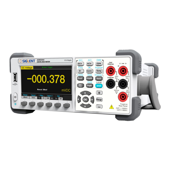
SIGLENT Front Panel SDM3055 Digital Multimeter provides users with brief and clear front panel. These control buttons are group by logic and users only need choose corresponding buttons to carry out basic operations, as shown in Diagram 1-4. Diagram 1- 4 Front Panel Overview... -
Page 15: Back Panel
SIGLENT Back Panel SDM3055 Digital Multimeter’s Back Panel provides users with abundant interfaces, including USB Device、USB Host、LAN and GPIB(Only for SDM3055A), as shown in the following diagram. Diagram 1- 5 Back Panel Overview Power Socket Power Fuse AC Voltage Selector Inspection card interface USB Device(USBTMC)... -
Page 16: Power On
SIGLENT Power On Please power on the instrument as the following steps: 1. Adjust AC Voltage Selector to 110 (100~120V, 45~440Hz, AC) or 220 (200~240V, 50/60Hz, AC) in accordance with power standards in your country; 2. Connect the instrument to AC supply via power cord supplied by SIGLENT;... -
Page 17: User Interface
SIGLENT User Interface Single Display: Trigger Mode Main Display Function Reading Display Softkey Menu Measurement Range Unit Diagram 1- 6 Single Display Interface Dual-Display: Main Display Function Main Display Vice-display Diagram 1-7 User Interface SDM3055 Digital Multimeter... -
Page 18: Chapter 2 Function And Operation
SIGLENT Chapter 2 Function and Operation To Measure DC Voltage / Current To Measure AC Voltage / Current To Measure 2-Wire / 4-Wire Resistance To Measure Frequency / Capacitance To Test Continuity / Diode To Measure Temperature / Optional Multiple Scan Card ... -
Page 19: To Select Measurement Range
SIGLENT To Select Measurement Range The Multimeter has two kinds of modes of selecting measurement range: “Auto” and “Manual”. It can select appropriate range according to the signals input in Auto mode, which is very convenient for users. While in Manual mode, you can obtain higher reading precision. - Page 20 SIGLENT Diagram 2- 2 Range selection menus Explanations: 1. When the input signal is beyond the current scope of the measurement range, the Multimeter will show “overload”. 2. Range option will turn back to default setting “Auto” after restarting and remote reset.
-
Page 21: To Select Measurement Speed
SIGLENT To Select Measurement Speed The instrument provides three types of measurement rate: 5 reading/s, 50 reading/s and 150 reading/s. 5 reading/s belongs to “Slow” rate; 50 reading/s belongs to “Middle” rate; 150 reading/s belongs to “Fast” rate. Measurement speed can be controlled by softkey menu. Press 【Speed】 and then press 【Slow】,【Middle】or【Fast】to choose measurement speed. -
Page 22: Basic Measurement Functions
SIGLENT Basic Measurement Functions SDM3055 Digital Multimeters have following basic functions: To Measure DC Voltage To Measure AC Voltage To Measure DC Current To Measure AC Current To Measure 2/4-Wire Resistance To Measure Capacitance ... -
Page 23: To Measure Dc Voltage
SIGLENT To Measure DC Voltage The Multimeter enables to measure DC Voltage up to 1000V. The method to connect and measure DC Voltage will be introduced in details as the following steps. (NOTE: DC Voltage is always the selected function when the... - Page 24 SIGLENT 3. Choose a proper voltage range according to the measured circuit. Table 2- 1 Measurement Characteristics of DC Voltage 200mV、2V、20V、200V、1000V Ranges* 1000V on all ranges(HI terminal) Input Protection Configurable Range, DC input impedance, Rel NOTE*: All the ranges enable to obtain 20% value higher than original except 1000V.
-
Page 25: To Measure Dc Current
SIGLENT To Measure DC Current The Multimeter enables to measure DC Current up to 10A. The method to connect and measure DC Current will be introduced in details as the following steps. Operating Steps: 1. Press on the front panel to enter the DC Current measurement interface, as shown in Diagram 2- 6. - Page 26 SIGLENT 3. Choose a proper current range according to the measured circuit. Table 2- 2 Measurement Characteristics of DC Current 200μA、2mA、20mA、200mA、2A、10A Ranges* Input Protection 10A(back panel), 12A(inside the instrument) Configurable Range, Rel NOTE*: All the ranges enable to obtain 20% value higher than original except 10A.
-
Page 27: To Measure Ac Voltage
SIGLENT To Measure AC Voltage The Multimeter enables to measure AC Voltage up to 750V. The method to connect and measure DC Voltage will be introduced in details as the following steps. Operating Steps: 1. Press on the front panel to enter the AC Voltage measurement interface, as shown in Diagram 2- 8. - Page 28 SIGLENT 3. Choose a proper voltage range according to the measured circuit. Table 2- 3 Measurement Characteristics of AC Voltage 200mV、2V、20V、200V、750V Ranges* 750Vrms on all ranges(HI terminal) Input Protection Configurable Range, Rel NOTE*: All the ranges enable to obtain 20% value higher than original except 750V.
-
Page 29: To Measure Ac Current
SIGLENT To Measure AC Current The Multimeter enables to measure AC Current up to 10A. The method to connect and measure AC Current will be introduced in details as the following steps. Operating Steps: 1. Press on the front panel to enter the AC Current measurement interface, as shown in Diagram 2- 11. - Page 30 SIGLENT 3. Choose a proper current range according to the measured circuit. Table 2- 4 Measurement Characteristics of AC Current 200μA、2mA、20mA、200mA、2A、10A Ranges* 10A(back panel), 250V(fuse), 12A(inside the Input Protection instrument) Configurable Range, Rel NOTE*: All the ranges enable to obtain 20% value higher than original except 10A.
-
Page 31: To Measure 2-Wire/4-Wire Resistance
SIGLENT To Measure 2-Wire/4-Wire Resistance The Multimeter enables to measure 2-Wire Resistance and 4-Wire Resistance. The method to connect and measure 2-Wire/4-Wire Resistance will be introduced in details separately. 2-Wire Resistance Operating Steps: 1. Press on the front panel to enter the 2-Wire Resistance measurement interface, as shown in Diagram 2- 13. - Page 32 SIGLENT 3. Choose a proper resistance range according to the scope. Table 2- 5 Measurement Characteristics of 2-Wire Resistance 200μA、2mA、20mA、200mA、2A、10A Ranges* Open-circuit Voltage <8V Input Protection 1000V on every range (HI terminal) Configurable Range, Rel NOTE*: All the ranges enable to obtain 20% value higher than original. Besides, both Manual and Auto are available for setting every range.
- Page 33 SIGLENT 4-Wire Resistance Operating Steps: 1. Press on the front panel to enter the 4-Wire Resistance measurement interface, as shown in Diagram 2- 14. Diagram 2- 15 4-Wire Resistance Measurement Interface 2. Connect the red lead to terminal Input-HI and black lead to terminal Input-LO as the following diagram.
- Page 34 SIGLENT 3. Choose a proper resistance range according to the scope. Table 2- 6 Measurement Characteristics of 4-Wire Resistance 200Ω、 2kΩ、 20kΩ、 200kΩ、 2MΩ、 10MΩ、 100MΩ Ranges* Open-circuit Voltage <8V (1) 1000V on each range (HI terminal) Input Protection (2) 200V on each range (HI Sense, LO Sense)
-
Page 35: To Measure Capacitance
SIGLENT To Measure Capacitance The Multimeter enables to measure Capacitance up to 1000μF. The method to connect and measure Capacitance will be introduced in details as the following steps. Operating Steps: 1. Press on the front panel to enter the Capacitance measurement interface, as shown in Diagram 2- 16. - Page 36 SIGLENT 3. Choose a proper capacitance range according to the measured circuit. Table 2- 7 Measurement Characteristics of Capacitance 2nF、 20nF、 200nF、 2μF、 200μF、 200μF、 10000μF Ranges* Input Protection 1000V on all ranges (HI terminal) Configurable Parameters Range, Rel NOTE*: All the ranges enable to obtain 20% value higher than original.
-
Page 37: To Measure Frequency Or Period
SIGLENT To Measure Frequency or Period The Frequency or Period of a signal could be obtained by Dual-display Function during measuring its voltage or current or by the function button on the front panel. The method to connect and measure Frequency or Period will be introduced in details as the following steps. - Page 38 SIGLENT 3. Choose a proper voltage range according to the measured circuit. Table 2- 8 Measurement Characteristics of Frequency Ranges 200mV, 2V, 20V, 200V, 750V Measurement Range 20Hz ~ 1MHz Input Protection 750Vrms on all ranges (HI terminal) Configurable 4. Set relative value (Optional operation).
- Page 39 SIGLENT To Measure Period Operating Steps: on the front panel and select 【Period】to enter 1. Press the Period measurement interface. The lower right corner of the screen shows the unit of Period, as shown in Diagram 2- 21. Diagram 2- 21 Period Measurement Interface 2.
- Page 40 SIGLENT 4. Set relative value (Optional operation). Press 【Rel】to open or close Relative math function. When it is open, the reading displayed is a relative value which comes from the result of actual measurement value subtracts the value that has been set. (Please refer to “...
-
Page 41: To Test Continuity
SIGLENT To Test Continuity Continuity test uses double leads method to measure the resistance of the measured circuit via about 0.5mA current. When the measured resistance in circuit is lower than the selected one, it is considered being connected with instrument. - Page 42 SIGLENT 3. Set the Short-circuit resistance. The default value is set as 50Ω before leaving factory. The value can be changed by using direction keys. You also can execute the Continuity measurement directly without modification. Table 2- 10 Measurement Characteristics of Continuity...
-
Page 43: To Test Diode
SIGLENT To Test Diode If input voltage is under +0.7V (about 1.4kΩ), the Beeper will beep one time. If input voltage is under 50mV (about 100Ω) the Beeper will beep persistently. The method to test Diode will be introduced in details as the following steps. - Page 44 SIGLENT 3. Set the Beeper function. Press 【Beeper】 to turn on or off the Beeper. If the circuit is continuous, the nstrument will beep once when the Beeper is turned on. Table 2- 11 Characteristics of Checking Diodes Test Current...
-
Page 45: To Measure Temperature
SIGLENT To Measure Temperature The Multimeter supports for two types of temperature sensor: TC and RTD. The method to connect and measure Temperature will be introduced in details as the following steps. Operating Steps: 1. Press on the front panel to enter the Temperature measurement interface, as shown in Diagram 2- 27. - Page 46 SIGLENT Diagram 2- 29 Load a Configuration File 4. Press 【Define】to view the configuration, as shown in the following diagram: Diagram 2- 30 Configuration of the Sensor 5. Press 【Display】 to choose a display mode. The Multimeter supports three display modes: Temperature Value, Measured Value and All.
- Page 47 SIGLENT Press 【All】, the measured value will be shown on the Vice display and the corresponding value will be shown on the Main display at the same time, which is convenient for users to observe temperature and voltage values. Diagram 2- 32 Show Temperature And Voltage Values 6.
-
Page 48: Measurement Parameters
SIGLENT Measurement Parameters The parameters have been configured before the Multimeter leaving factory. Users can either measure directly or modify them to meet your own requirements. AC Filter AC Filter is applicable for DC Voltage and DC Current measurement. When DC Voltage or DC Current function is selected, press 【Filter】... -
Page 49: Dc Input Impedance
SIGLENT DC Input Impedance DC input impedance is only applicable for DC voltage measurement. When DC Voltage function is selected, press【Range】 and select 【200mV】 or 【2V】 to show the menu【Input Z】, as the following diagram shows. Diagram 2- 35 Choose DC Input Impedance The options of input impedance for DC voltage measurements are 10MΩ... -
Page 50: Short-Circuit Resistance
SIGLENT Short-circuit Resistance Set up the short-circuit resistance value in the short-circuit test menu. When the measured resistance is lower than the short-circuit resistance, the circuit is considered as connected, and the beeper sounds (if sound is turned on). The short-circuit resistance is only applicable to the continuity test. -
Page 51: Dual-Display Function
SIGLENT Dual-display Function Dual-display function is used to improve test and measurement functions. Press to open Dual-display function and the upper right corner will show “Dual”. By this time, press a function key if this function can be used as the vice display, it will be displayed in the Vice Display. - Page 52 SIGLENT 2. If different measurement functions are used in both Main and Vice Display. The readings in both of the display will update alternately. If math function (dBm, dB) is used in Main Display, when opening Vice Display, math operation will be closed automatically and Vice Display will show the second selected function normally.
-
Page 53: Utility Function
SIGLENT Utility Function The Utility function enables users to set up system parameters, interface parameters of the multimeters. Press to enter the operating menu of Utility function, as the following diagram shows. Diagram 2- 37 Utility Function Configuration Interface Table 2- 13 Utility Function Menu Description... -
Page 54: Store And Recall
SIGLENT Store and Recall The Store/Recall function enables users to store and recall the instrument parameters and data files in the local storage as well as in USB storage. Operating Steps: 1. After entering into the function menu of Utility, press 【Store/Recall】to enter the interface as shown in diagram 2-38. - Page 55 SIGLENT Table 2- 14 Storage Function Menu Description Function Settings Description Menu Browse Choose the location that file will be saved. File Input a file name. Name Type .xml / .csv Choose the type that the file is saved. Store...
-
Page 56: Manage File
SIGLENT Manage File The Manage File function enables users to create a new folder and save, copy, rename or delete files in the local storage as well as in USB storage. Operating Steps: 1. After entering into the function menu of Utility, press【Manage File】to enter the interface as shown in diagram 2-41. - Page 57 SIGLENT The method of inputting file name: Press direction keys to select a desired char in the input area. Press “OK” key on the front panel to input selected char in the input area. Press【Clear All】to clear all input chars.
-
Page 58: I/O Configuration
SIGLENT I/O Configuration Press【I/O Config】to enter the following interface and set up the parameters. Diagram 2- 43 I/O Configuration Interface LAN Settings The Multimeter enables users to operate instrument remotely by LAN interface and store or recall internet settings. You can look over current LAN settings and set up IP address and subnet mask. - Page 59 Done Save all changes and return to the higher level menu. GPIB Settings (Only for SDM3055A) Each device on the GPIB (IEEE–488) interface must have a unique address. The default address is 30 when the instrument is leaving the factory. The address of Multimeter can be any integral value between 1 and 30.
-
Page 60: Board Test
SIGLENT Board Test SDM3055 provides self-test functions, including Key Test, LCD Test, Beeper Test and Chip Test. Operating Steps: 1. Press , then choose【Test/Admin】→【Board Test】 to enter the following interface. Diagram 2- 46 Board Test Interface Table 2- 17 Board Test Function Description... - Page 61 SIGLENT Diagram 2- 47 Key Test Interface NOTE: Before you operate, the shapes on the screen display blue color. The corresponding area of tested buttons or knobs would display green color. Press【Done】to exit the test. 3. Test the LCD screen.
- Page 62 SIGLENT 4. Test the beeper. Press 【Beeper】to test the beeper. Under regular circumstance, press 【Beeper】 one time and the instrument will beep one time. 5. Test the chips. Press【Chip】→【Start】to enter chip test interface, as Diagram 2-49 shows. Diagram 2- 49 Chip Test Interface NOTE: ...
-
Page 63: Firmware Update
SIGLENT Firmware Update The software of the Multimeter can be updated directly via USB flash drive, updating current software version to desired software version. Operating Steps: 1. Copy the update file to the USB flash drive. 2. Insert USB flash drive to USB host interface on the front panel of the Multimeter. -
Page 64: System Setup
SIGLENT System Setup Press , then select【System Setup】to enter the following interface. Diagram 2- 51 System Setup Interface Table 2- 18 System Settings Menu Description Function Menu Description Language Select the display interface language. Screen Set up the screen protection function. - Page 65 SIGLENT 2. Set up the time of screen protection. Press【Screen】to set screen protection as 1 Min, 5 Mins, 15 Mins, 30 Mins, 1 Hour, 2 Hours or 5 Hours according to different demands. Activate the screen saver program and screen saver will be on if no action is taken within the time that you have selected.
-
Page 66: Acquire
SIGLENT Acquire Sampling is a process of acquiring and digitizing signal. The optional Trigger methods of the Multimeter include Auto Trigger, Single Trigger and External Trigger. Press to enter the interface shown as the following diagram: Diagram 2- 52 Acquire Interface... -
Page 67: Auto Trigger
SIGLENT Auto Trigger Auto Trigger parameters that need to be set up include delay, samples/ trigger and VMC out. Operating Steps: , then select 【Trg Src】 → 【Auto】 or press 1. Press on the front panel directly to enable Auto Trigger. -
Page 68: Single Trigger
SIGLENT Single Trigger Single Trigger parameters that need to be set up include delay, samples /trigger and VMC out. Operating Steps: , then select 【Trg Src】→【Single】or press 1. Press on the front panel directly to enable Single Trigger. See the diagram below. -
Page 69: External Trigger
SIGLENT External Trigger The external trigger signal will be input via EXT TRIG interface on the rear panel. External trigger parameters that need to be set up include delay, samples /trigger, slope and VMC out. Operating Steps: , then select 【Trg Src】→【Ext】or press 1. -
Page 70: Help System
SIGLENT Help System SDM3055 provides powerful built-in help system. You can recall help information at any time during using the instrument. You also can get a particularly help for every button on the front panel or menu softkey by using the built-in help system. - Page 71 SIGLENT Measuring Capacitance. Get the method to measure temperature. Math Function. Introduce how to use the math function while you are measuring. Dual-display Function. Get the method to use the dual-display function while you are measuring. Saving and Recalling Information.
-
Page 72: Math Function
SIGLENT Math Function The Multimeter provides five math functions: Statistics, Limits, dBm, dB and Relative. Choose different math functions to meet different measurement demands. Math functions can only be used in DC Voltage, AC Voltage, DC Current, AC Current, Resistance, Frequency, Period and Temperature measurement. - Page 73 SIGLENT Table 2- 21 Math Function Menu Description Function Settings Description Menu Reading statistic functions, including: max, min, Statistics average, span, std dev and samples. The Limits function performs Pass/Fail testing Limits according to the specified upper and lower limits.
-
Page 74: Statistics
SIGLENT Statistics There are many kinds of reading statistic functions, including: Max, Min, Average, Standard deviation and so on. The Statistic function is available for DC Voltage, AC Voltage, DC Current, AC Current, Resistance, Frequency, Period, Capacitance and Temperature measurement. - Page 75 SIGLENT Statistics Function: In statistic function, the first reading is usually set to the maximum or minimum value. When getting more readings, current displaying value is always the maximum/minimum reading among all the measured values. The maximum, minimum, average and reading quantities are stored in volatile memory.
-
Page 76: Limits
SIGLENT Limits Limits function is available to prompt signals beyond ranges according to the upper and lower parameters. Following are some measurement functions which are able to do limit operation: DC Voltage, AC Voltage, DC Current, AC Current, Resistance, Frequency, Period, Capacitance and Temperature. - Page 77 SIGLENT 1. How to Set Limits Select 【High】,【Low】,【Center】or【Span】 and then switch to the needed digit by Left or Right Direction keys and input numerical value by Up and Down Direction keys. 2. Unit The unit of Limits is decided by the current measurement function.
-
Page 78: Dbm
SIGLENT The dBm function is logarithmic and based on a calculation of power delivered to a reference resistance, relative to 1 mill watt. Besides,this function only applies to AC voltage and DC voltage measurements. →【dB/dBm】→【On】and select【Function dBm】to enter the Press interface shown in the following diagram. - Page 79 SIGLENT Each dB measurement is different between the input signal and a stored relative value, with both values converted to dBm. The dB function applies to AC voltage and DC voltage measurements only. → 【dB/dBm On】 and select 【 Function dB】 to enter the interface Press shown in the following diagram.
-
Page 80: Relative Value
SIGLENT Relative Value Relative value is used for relative measurement. Actual measurement reading is the depression between measurement value and preset value. The Multimeter allows operating for the following parameters: DC Voltage, AC Voltage, Current, Current, Resistance, Frequency, Period, Capacitance and Temperature. -
Page 81: Display Mode
SIGLENT Display Mode The Multimeter supports four types of way to view measured data: “Number”, “Bar Meter” ”Trend Chart” and “Histogram”. Number to open the menu of display mode and press 【Display】 Press to enter the following interface. “Number” is always the selected mode when the Multimeter is turned on. - Page 82 SIGLENT Bar Meter Operating Steps: 1. Press【Bar Meter】to enter Bar Meter display mode. Diagram 2- 64 Bar Meter Display Mode 2. Press【Horizontal Scale】to choose the way to set the vertical scale as Default or Manual mode. Table 2- 27 To Set the Vertical Scale of Bar Meter manually...
- Page 83 SIGLENT Trend Chart Operating Steps: 1. Press 【Trend Chart】 to enter Trend Chart display mode. The default vertical scale is -2V to 2V when DC Voltage measurement is selected. Diagram 2- 65 Trend Chart Display Mode Table 2- 28 Trend Chart Display Mode...
- Page 84 SIGLENT Press【Manual】and you can set the vertical scale manually, as the following diagram shows. Diagram 2- 67 Manual Vertical Scale SDM3055 Digital Multimeter...
- Page 85 SIGLENT Histogram Operating Steps: 1. Press【Histogram】to enter Histogram display mode. Diagram 2- 68 Histogram Display Mode Table 2- 29 Histogram Display Mode Function Settings Description Menu Display Currently selected display mode is Histogram. Histogram Binning Set Binning as Auto or Manual mode.
- Page 86 SIGLENT Table 2- 30 Bin Set Function Settings Description Menu Set the number of Bins, 10, 20, 40, 100, 200 or 400 Num.Bins selected. Set the low value of horizontal scale. High Set the high value of horizontal scale. Center Set the center value of horizontal scale.
-
Page 87: Trigger
SIGLENT Trigger The Multimeter supports Trigger function. Press on the front panel to trigger the Multimeter by Auto or Single mode .Auto trigger is considered as a default when the power is on. Auto Trigger Press on the front panel one time and Auto Trigger will be started to capture continuous readings automatically. -
Page 88: Hold Measurement Function
SIGLENT Hold Measurement Function Hold Measurement function provides users with a stable reading on the screen of the front panel. When the test leads are put away, the reading is still held on the screen, which makes users can view measured history data. -
Page 89: Chapter 3 Application Examples
SIGLENT Chapter 3 Application Examples This chapter mainly introduces few application examples to help users control and manipulate SDM3055 quickly. Example 1: Reading Statistic Functions Example 2: To Eliminate Leads Impedance Example 3: dBm Measurement Example 4: dB Measurement ... -
Page 90: Example 1: Reading Statistic Functions
SIGLENT Example 1: Reading Statistic Functions Introduce how to realize the statistic function during measuring. When continually measuring few readings, the Multimeter will update statistic values constantly. Operating Steps: 1. Press on the front panel to select AC Voltage measurement function and choose a proper voltage range. -
Page 91: Example 2: To Eliminate Leads Impedance
SIGLENT Example 2: To Eliminate Leads Impedance Relative Operation could eliminate impedance errors from leads when measuring smaller resistance. Operating Steps: 1. Press on the front panel to select 2-Wire Resistance measurement function. 2. Connect the red lead to terminal Input-HI and black lead to terminal Input-LO as Diagram 2-14. - Page 92 SIGLENT 6. Besides, pressing【Rel】on the softkey menu could also open Relative operation. The Relative Operation has been turned on. Diagram 3- 5 Lead Impedance after Operation SDM3055 Digital Multimeter...
-
Page 93: Example 3: Dbm Measurement
SIGLENT Example 3: dBm Measurement dBm is commonly used in audio signal measurement. The following will introduce you how to measure dBm value. Operating Steps: 1. Press on the front panel to select AC Voltage measurement function and choose a proper voltage range. -
Page 94: Example 4: Db Measurement
SIGLENT Example 4: dB Measurement As a common measuring unit, dB has been widely used in electrical engineering, radio science, mechanics, shock and vibration, mechanical power and acoustics areas. The following will introduce you how to measure dB between two circuits. - Page 95 SIGLENT 5. Press【Done】to return to the higher level menu. At this time, the reading shown on the screen is the power difference between two circuits. Diagram 3- 9 dB Operation Result SDM3055 Digital Multimeter...
-
Page 96: Example 5: Limits Test
SIGLENT Example 5: Limits Test Limits Operation hints you the signal is overstep its range according to the selected High and Low Limit parameters; meanwhile the beeper makes a sound to alarm (if sound is on.) Operating Steps: 1. Press on the front panel to select AC Voltage measurement function and choose a proper voltage range. - Page 97 SIGLENT 4. Turn on the beeper and start Limits Test. As shown in Diagram 3-11. The measured result is between the Low and High limits, so the test status is “True”. 5. If changing the high limit value to 1V, the measured result is not between the Low and High limits.
-
Page 98: Example 6: Thermocouple Setting And Measurement
SIGLENT Example Thermocouple setting measurement Thermocouple is a common temperature sensor. Type, voltage and cold-side temperature are required for thermocouple measurement. The instrument can measure temperature of HI and LO terminals (cold-side), and calculate absolute temperature of hot-side. Besides, only the relationship between thermocouple voltage and cold-side temperature is need to be input according thermocouple type when you set the thermocouple sensor. - Page 99 SIGLENT Diagram 3- 14 Select the Type of Thermocouple 3. Use direction keys to select corresponding file and press【Read】to recall the sensor settings file. Diagram 3- 15 Select Sensor Settings File 4. Press 【Units】to choose the unit of temperature. 5. View measured result.
-
Page 100: Example 7: To Use Hold Measurement Function
SIGLENT Example 7: To Use Hold Measurement Function Reading Hold can help user to obtain a stable reading and hold it on the display of Front Panel. The reading would be held all the same although testing pen had been moved away. Then we will introduce how to keep the readings displayed on screen. - Page 101 SIGLENT Diagram 3- 18 Result 2 SDM3055 Digital Multimeter...
-
Page 102: Example 8: To Use Application Software Easysdm
SIGLENT Example 8: To Use Application Software EasySDM Remote Control function based on EasySDM enables users to operate instrument remotely. The software supports basic measurements, Acquire, Statistics, Trend Chart and Histogram, etc. The method to use the software will be introduced in details as the following steps. -
Page 103: Chapter 4 Measurement Tutorial
SIGLENT Chapter 4 Measurement Tutorial True RMS AC Measurement The AC measurement of the Multimeter has true RMS response. The power dissipated in a resistor within a time is proportional to the square of the measured true RMS voltage, independent of wave shape. The instrument can accurately measure true RMS voltage or current, as long as the wave shape contains negligible energy above the effective bandwidth. -
Page 104: Crest Factor Errors (Non-Sinusoidal Inputs)
SIGLENT Crest Factor Errors (non-sinusoidal inputs) A common misconception is that "since an ac Multimeter is true RMS, its sine wave accuracy specifications apply to all waveforms." Actually, the shape of the input signal can dramatically affect measurement accuracy. A common way to describe signal wave shapes is “crest factor”. -
Page 105: Loading Errors (Ac Voltage)
SIGLENT Loading Errors (AC Voltage) In the AC Voltage function, the input of SDM3055 appears as a 1MΩ resistance in parallel with 100pF of capacitance. The test lead that you use to connect signals to the Multimeter will also add additional capacitance and loading. -
Page 106: Application Of The Analog Filter
SIGLENT Application of the Analog Filter The analog filter of the Multimeter can be used to reduce the influence of the AC component in DC measurement. Generally the filter may not be required, but sometimes it can improve the DC measurement. For example, if the measured DC electrical source has a big AC ripple, the analog filter can reduce the influence. -
Page 107: Chapter 5 General Troubleshooting
(3) Check if the capacity of the used USB disk is too large. The Multimeter is recommended not to use USB disks which exceed 4GB. (4) After restarting the instrument, insert the USB disk again to inspect. (5) If you still can’t use the USB disk properly, please contact SIGLENT. SDM3055 Digital Multimeter... -
Page 108: Chapter 6 Appendix
We suggest that the length of USB data wire and LAN cable connected to the instrument should be less than 3m to avoid affecting the product performance. All the accessories are available by contacting your local SIGLENT office. SDM3055 Digital Multimeter... -
Page 109: Appendix B: Warranty Summary
SIGLENT Appendix B: Warranty summary SIGLENT warrants that the products that it manufactures and sells will be free from defects in materials and workmanship for a period of three years from the date of shipment from an authorized SIGLENT distributor. If a product proves defective within the respective period, SIGLENT will provide repair or replacement as described in the complete warranty statement. -
Page 110: Appendix C: Daily Maintenance And Cleaning
SIGLENT Appendix C: Daily Maintenance and Cleaning Maintenance When storing or placing the instrument, please avoid the liquid crystal display from direct sunlight for a long time. NOTE: To avoid damages to the instrument or probe, please don’t place them in mist, liquid or solvent. -
Page 111: Appendix D: Contact Siglent
SIGLENT Appendix D: Contact SIGLENT SIGLENT TECHNOLOGIES CO., LTD. Address: 3F, NO.4 building, Antongda Industrial Zone, 3rd Liuxian Road, 68th District, Baoan District, Shenzhen, P.R. China Tel: +86-755-36615186 Fax: +86-755-3591582 Post Code: 518101 E-mail: sales@siglent.com Http://www.siglent.com SDM3055 Digital Multimeter... - Page 112 Quick Strat SDM3055 Digital Multimeter QS06035-E02A 2014 SIGLENT TECHNOLOGIES CO.,LTD...
- Page 114 SIGLENT TECHNOLOGIES CO., LTD. All rights reserved. ● The information provided in this manual replaces all information printed before. ● SIGLENT Company has the rights to change the specification and the price. ● Contents in this manual are not allowed to be copied, extracted and translated without permission by the company.
-
Page 115: General Safety Summary
Do not operate with suspected failures If you suspect that the product is damaged, please contact SIGLENT’s qualified service personnel to inspect it. Any repair and adjustment to the product or replacing a component should be done by qualified personnel only. - Page 116 SIGLENT Avoid circuit or wire exposure Don’t touch exposed contacts or components when the power is on. Don’t operate without covers. Don’t operate the instrument with covers or panels removed. Use proper fuse. It’s only allowed to use the specified fuse for the instrument.
- Page 117 SIGLENT Input terminal protection limitation Protection limitation is defined for the input terminal: 1. Main input(HI and LO)terminal HI and LO terminals are used for Voltage, Resistance, Capacitance, Continuity, Frequency, Diode and temperture measurement. Two protection limitations are defined: HI-LO protection limitation: 1000VDC or 750AVC. It’s the maximum measurable voltage.
- Page 118 SIGLENT IEC Measurement Category II Overvoltage Protection SDM3055 Digital Multimeter provides overvoltage protection for line-voltage mains connections meeting both of the following conditions to avoid the danger of electric shock: 1. The HI and LO input terminals are connected to the mains under Measurement Category II conditions as following.
-
Page 119: Safety Terms And Symbols
SIGLENT Safety Terms and Symbols Terms in this manual. Terms may appear in this manual: WARNING: Warning statements indicate the conditions and behaviors that could result in injury or loss of life. CAUTION: Caution statements indicate the conditions and behaviors that could result in damage to this product or other properties. -
Page 120: Daily Maintenance And Cleaning
SIGLENT Daily Maintenance and Cleaning Maintenance When storing or placing the instrument, please avoid the liquid crystal display from direct sunlight for a long time. NOTE: To avoid damages to the instrument or test leads, please don’t place them in mist, liquid or solvent. - Page 121 Connect Power Cord ..................6 Power Selection ..................... 7 Change the Power Fuse ................7 Connect Test Leads ..................8 Connect USB and LAN Ports ..............14 Use Safety Lock ................... 15 Troubleshooting ................... 16 Contact SIGLENT ..................18 VIII SDM3055 Quick Start...
-
Page 122: General Inspection
Damages of the instrument caused by the shipment will be compensated by the shipper or carrier. SIGLENT will not be responsible for the free repair or replacement. 2. Inspect the instrument. -
Page 123: Appearance And Size
SIGLENT Appearance and Size 260 mm Front View 282 mm Side View 2 SDM3055 Quick Start... -
Page 124: To Adjust The Handle
SIGLENT To adjust the Handle Please grip the handle by the two sides and pull it outward to adjust the handle position of SDM3055. Then rotate the handle to the appropriate position. Please operate as the following figure: Handle Adjustment... -
Page 125: Front Panel
SIGLENT Front Panel LCD Display USB Host Power Key Menu Operation Keys Basic measurement keys Auxiliary Measurement Keys Enable trigger key Range/Direction Keys Signal input terminals 4 SDM3055 Quick Start... -
Page 126: Rear Panel
SIGLENT Rear Panel Power Socket Power Fuse AC Voltage Selector Inspection card USB Device(USBTMC) VMC Output Ext trigger Current Input Fuse Explanation:[1] Only SDM3055S support inspection card. SDM3055 Quick Start 5... -
Page 127: Connect Power Cord
User Manual to change the fuse if needed. 4. After the above inspections, the power key is still not lit, please contact SIGLENT for help. 6 SDM3055 Quick Start... -
Page 128: Power Selection
SIGLENT Power Selection The Multimeter is able to operate on multiple power distribution standards and must be set up according to the supply voltage. If the selected supply voltage doesn’t match the working voltage while using, the setting of the Multimeter’s supply voltage must be changed. -
Page 129: Connect Test Leads
SIGLENT Connect Test Leads 1. DC Voltage Measurement Connect the test leads and tested circuit as the following figure, red test lead to the HI Terminal and black lead to the LO Terminal. 2. AC Voltage Measurement Connect the test leads and tested circuit as the following diagram, red test lead to the HI Terminal and black lead to the LO Terminal. - Page 130 SIGLENT 3. DC Current Measurement Connect the test leads and tested circuit as the following diagram, red test lead to the HI Terminal and black lead to the LO Terminal. 4. AC Current Measurement Connect the test leads and tested circuit as the following diagram, red test lead to the HI Terminal and black lead to the LO Terminal.
- Page 131 SIGLENT 5. 2-Wire Resistance Measurement Connect the test leads and tested circuit as the following diagram, red test lead to the HI Terminal and black lead to the LO Terminal. 6. 4-Wire Resistance Measurement Connect the test leads and tested circuit as the following diagram, red test lead to the HI Terminal and black lead to the LO Terminal.
- Page 132 SIGLENT 7. Capacitance Measurement Connect the test leads and tested capacitor as the following diagram, red test lead to the positive pole of the capacitor and black lead to the negative pole. 8. Continuity Testing Connect the test leads and tested circuit as the following diagram, red test lead to the HI Terminal and black lead to the LO Terminal.
- Page 133 SIGLENT 9. Diode Testing Connect the test leads and tested diode as the following diagram, red test lead to the HI Terminal and black lead to the LO Terminal. 10. Frequency/Period Measurement Connect the test leads as the following diagram, red test lead to the HI Terminal and black lead to the LO Terminal.
- Page 134 SIGLENT 11. Temperture Measurement Connect the test leads and tested circuit as the following diagram, red test lead to the HI Terminal and black lead to the LO Terminal. TC and RTD Sensor SDM3055 Quick Start 13...
-
Page 135: Connect Usb And Lan Ports
SIGLENT Connect USB and LAN Ports SDM3055 has plenty of I/O ports. To use any of the ports, follow the next instruction: Connect USB Host Connect USB Device Connect LAN 14 SDM3055 Quick Start... -
Page 136: Use Safety Lock
SIGLENT Use Safety Lock You can use the safety lock to lock the multimeter in a fixed place if necessary. The methods are as the following: 1. Align the key into the keyhole in the vertical direction of the back panel. -
Page 137: Troubleshooting
When you find them, please deal with them in the following corresponding ways. If the problem proves to be unsolvable by yourself, please contact SIGLENT for help. 1. If the screen is still dark with nothing displayed after pressing the power key: (1) Check if the power is correctly connected. - Page 138 It is suggested that the capacity of the USB matches to the multimeter is no larger than 4 G. (4) Restart the instrument and then insert the USB to check (5) If it is still in abnormal use, please contact SIGLENT. SDM3055 Quick Start 17...
-
Page 139: Contact Siglent
SIGLENT Contact SIGLENT SIGLENT TECHNOLOGIES CO.,LTD Address:3/F, building NO.4, Antongda Industrial Zone, 3rd Liuxian Road, Bao’an District, Shenzhen, P.R.China Tel:0086-755-3661 5186 E-mail:sales@siglent.com Http://www.siglent.com 18 SDM3055 Quick Start... - Page 140 Remote Manual SDM3055/SDM3055A Digital Mulimeter RC06035-E01A 2014 SIGLENT TECHNOLOGIES CO.,LTD...
- Page 141 2.4 CALCulate:SCALe Subsystem ..................26 2.5 CALCulate:AVERage Subsystem ..................31 2.6 CONFigure Subsystem ..................... 35 2.7 DATA Subsystem ......................44 2.8 MEASure Subsystem ......................46 2.9 SENSe Subsystem Introduction ..................54 2.10 SYSTem Subsystem ......................90 2.11 TRIGger Subsystem ......................92 SDM3055/SDM3055A...
-
Page 142: Scpi Command
MIN"). Optional parameters are enclosed in square brackets ( [ ] ). The brackets are not sent with the command string. If you do not specify a value for an optional parameter, the instrument uses a default value. SDM3055/SDM3055A... -
Page 143: Command Separators
For example,The following example sets the trigger count to 10 measurements: TRIG:COUN 10 You can then query the count value by sending: TRIG:COUN? You can also query the minimum or maximum count allowed as follows: TRIG:COUN? MIN TRIG:COUN? MAX SDM3055/SDM3055A... -
Page 144: Ieee-488.2 Common Commands
The command keyword is separated from the first parameter by a blank space. Use a semicolon ( ; ) to separate multiple commands as shown below: *RST; *CLS; *ESE 32; *OPC? SDM3055/SDM3055A... -
Page 145: Scpi Parameter Types
"OFF" or "0". For a true condition, the instrument will accept "ON" or "1". When you query a Boolean setting, the instrument will always return "0" or "1". The following example requires a Boolean parameter: DISPlay:STATe {ON|1|OFF|0} SDM3055/SDM3055A... -
Page 146: Command In This Manual
//Set the trigger state for “wait for trigger” ABOR //Interrupt the measurement This command may be used to abort a measurement when the instrument is waiting for a trigger, or for aborting a long measurement or series of measurements. SDM3055/SDM3055A... -
Page 147: Fetch
Reading Mem Ovfl bit (bit 14) is set in the Questionable Data Register's condition register (see Status System Introduction). The instrument clears all measurements from reading memory when the measurement configuration changes, or when any of these commands is executed: INITiate MEASure:<function>? READ? *RST SYSTem:PRESet SDM3055/SDM3055A... -
Page 148: Initiate[:Immediate]
Data Register's condition register (see Status System Introduction). To retrieve the measurements from the reading memory, use FETCh?. Use DATA:REMove? or R? to read and erase all or part of the available measurements. The ABORt command may be used to return to idle. SDM3055/SDM3055A... -
Page 149: Output:trigger:slope
VM Comp connector will output a positive pulse as each measurement is completed: CONF:VOLT:DC 10 SAMP:COUN 2 OUTP:TRIG:SLOP POS INIT This parameter is set to its default value after a Factory Reset (*RST) or Instrument Preset (SYSTem:PRESet). SDM3055/SDM3055A... - Page 150 Reading Mem Ovfl bit (bit 14) is set in the Questionable Data Register's condition register (see Status System Introduction). The instrument clears all measurements from reading memory when the measurement configuration changes, or when any of these commands is executed: INITiate MEASure:<function>? READ? *RST SYSTem:PRESet SDM3055/SDM3055A...
-
Page 151: Read
Reading Mem Ovfl bit (bit 14) is set in the Questionable Data Register's condition register . It is important to note that the following command will measurements to empty, leading to FETCh? The return value of the change: INITiate MEASure:<function>? READ? *RST SYSTem:PRESet SDM3055/SDM3055A... - Page 152 Reading Mem Ovfl bit (bit 14) is set in the Questionable Data Register's condition register . This parameter is set to its default value after a Factory Reset (*RST) or Instrument Preset (SYSTem:PRESet). SDM3055/SDM3055A...
-
Page 153: Unit:temperature {C|F|K} Unit:temperature
The command also accepts CEL or FAR, but the query returns C or F. This parameter is set to its default value after a Factory Reset (*RST) or Instrument Preset (SYSTem:PRESet). SDM3055/SDM3055A... -
Page 154: System Command
Typical Return (none) (none) Clear all limits, histogram data, statistics, and measurements: CALC:CLE:IMM CALC:CLE:IMM The items cleared by this command are cleared synchronously, so that the histogram, statistics, and limit data all restart at the same time that measurements restart. SDM3055/SDM3055A... -
Page 155: Calculate:limit Subsystem
2.4 V will set bit 11 (Lower Limit Failed). *CLS STAT:PRES CONF:VOLT 10,.001 SAMP:COUN 100 CALC:LIM:LOW 2.4 CALC:LIM:UPP 3.6 CALC:LIM:STAT ON INIT *WAI STAT:QUES? Typical Response: +4096 (at least one measurement was above the upper limit) Command Summary CALCulate:LIMit:CLEar[:IMMediate] CALCulate:LIMit:{LOWer|UPPer}[:DATA] CALCulate:LIMit[:STATe] SDM3055/SDM3055A... - Page 156 11 and 12 in the Questionable Data Register when the measurement function changes, or when any of the executed: CALCulate:LIMit:STATe ON INITiate MEASure:<function>? READ? CALCulate:LIMit:CLEar *RST SYSTem:PRESet To clear statistics, limits, histogram data, and measurement data, use CALCulate:CLEar[:IMMediate]. SDM3055/SDM3055A...
- Page 157 12 ("Upper Limit Failed"). See STATus Subsystem Introduction for further information. A CONFigure command resets both limits to 0. This parameter is set to its default value after a Factory Reset (*RST) or Instrument Preset (SYSTem:PRESet). SDM3055/SDM3055A...
- Page 158 11 and 12 in the Questionable Data Register when the measurement function changes, or when any of the following commands is executed: CALCulate:LIMit:STATe ON INITiate MEASure:<function>? READ? CALCulate:LIMit:CLEar *RST SYSTem:PRESet The instrument turns this setting OFF when the measurement function is changed or after *RST or SYSTem:PRESet. SDM3055/SDM3055A...
-
Page 159: Calculate:transform:histogram Subsystem
CONF:VOLT:DC 10,0.001 SAMP:COUN 1000 CALC:TRAN:HIST:RANG:AUTO ON CALC:TRAN:HIST:POIN 100 CALC:TRAN:HIST:STAT ON INIT *WAI CALC:TRAN:HIST:ALL? Typical Response: +9.99383828E+00,+1.00513398E+01,+1000,<102 bin counts> Note: The above response indicates 102 bin counts because the histogram includes bins for values below and above the histogram range. SDM3055/SDM3055A... - Page 160 The number of measurements greater than the upper range value Range values are real numbers returned in the form +1.00000000E+00. The number of measurements and bin data are signed, positive integers returned in the form +100. SDM3055/SDM3055A...
- Page 161 CALCulate:CLEar[:IMMediate]. 2.3.3 CALCulate:TRANsform:HISTogram:COUNt? Returns the number of measurements collected since the last time the histogram was cleared. Parameter Typical Return (none) Return the number of measurements used to compute the current histogram: CALC:TRAN:HIST:COUN? SDM3055/SDM3055A...
- Page 162 You can specify the lower and upper range values using CALCulate:TRANsform:HISTogram:RANGe: {LOWer|UPPer}. Lower and upper range values are computed automatically if CALCulate:TRANsform:HISTogram:RANGe:AUTO is ON. This parameter is set to its default value after a Factory Reset (*RST) or Instrument Preset (SYSTem:PRESet). SDM3055/SDM3055A...
- Page 163 (CALCulate:TRANsform:HISTogram:RANGe:AUTO OFF). The instrument restarts automatic range value selection (if enabled) when INITiate, MEASure? or READ? is executed. This parameter is set to its default value after a Factory Reset (*RST) or Instrument Preset (SYSTem:PRESet). SDM3055/SDM3055A...
- Page 164 If no histogram data exists, 9.91E37 (Not a Number) is returned. Lower and upper range values are computed automatically if CALCulate:TRANsform:HISTogram:RANGe:AUTO is ON. This parameter is set to its default value after a Factory Reset (*RST) or Instrument Preset (SYSTem:PRESet). SDM3055/SDM3055A...
- Page 165 2.3.7 CALCulate:TRANsform:HISTogram[:ST·ATe]{ON|1|OFF|0} CALCulate:TRANsform:HISTogram[:STATe]? Enables or disables histogram computation. Parameter Typical Return {ON|1|OFF|0}, default OFF 0 (OFF) or 1 (ON) See Example. The instrument turns this setting OFF when the measurement function is changed or after *RST or SYSTem:PRESet. SDM3055/SDM3055A...
-
Page 166: Calculate:scale Subsystem
The dB relative value parameter is relative to the dBm reference set with CALCulate:SCALe:DBM:REFerence. The instrument sets the reference value to 0.0 with automatic reference selection enabled after a Factory Reset (*RST), an Instrument Preset (SYSTem:PRESet), a change in math function, or a change in measurement function. SDM3055/SDM3055A... - Page 167 Enable dBm scaling with a reference resistance of 600 Ω: CALC:SCAL:DBM:REF 600 CALC:SCAL:FUNC DBM CALC:SCAL:STAT ON The instrument sets the reference value to its default value after a Factory Reset (*RST), an Instrument Preset (SYSTem:PRESet), a change in math function, or a change in measurement function. SDM3055/SDM3055A...
- Page 168 Scaling function results must be in the range of -1.0E+24 to -1.0E-24, or +1.0E-24 to 1.0E+24. Results outside these limits will be replaced with -9.9E37 (negative infinity), 0, or 9.9E37 (positive infinity). This parameter is set to its default value after a Factory Reset (*RST) or Instrument Preset (SYSTem:PRESet). SDM3055/SDM3055A...
- Page 169 OFF:CALCulate:SCALe:DB:REFerence specifies the reference for DB scaling. The instrument enables automatic reference selection when the scaling function is enabled (CALCulate:SCALe:STATe ON). This parameter is set to its default value after a Factory Reset (*RST) or Instrument Preset (SYSTem:PRESet). SDM3055/SDM3055A...
- Page 170 CALC:SCAL:DBM:REF 50 CALC:SCAL:FUNC DB CALC:SCAL:REF:AUTO ON CALC:SCAL:STAT ON READ? Enabling the scaling function also enables automatic null value selection (CALCulate:SCALe:REFerence:AUTO). The instrument turns this setting OFF when the measurement function is changed or after *RST or SYSTem:PRESet. SDM3055/SDM3055A...
-
Page 171: Calculate:average Subsystem
SIGLENT Remote Manual 2.5 CALCulate:AVERage Subsystem This subsystem calculates measurement statistics. Command Summary CALCulate:AVERage[:STATe] CALCulate:AVERage:CLEar[:IMMediate] CALCulate:AVERage:ALL? CALCulate:AVERage:AVERage? CALCulate:AVERage:COUNt? CALCulate:AVERage:MAXimum? CALCulate:AVERage:MINimum? CALCulate:AVERage:PTPeak? CALCulate:AVERage:SDEViation? SDM3055/SDM3055A... - Page 172 Statistics are cleared when the measurement function changes or when any of these commands is executed: CALCulate:AVERage:STATe ON CALCulate:AVERage:CLEar INITiate MEASure:<function>? READ? *RST SYSTem:PRESet The instrument turns this setting OFF when the measurement function is changed or after *RST or SYSTem:PRESet. SDM3055/SDM3055A...
- Page 173 All values except the COUNt are returned in the form +1.23450000E+01. The count is as a signed, positive integer: +129. When dB or dBm scaling is used, the CALC:AVER:AVER and CALC:AVER:SDEV queries return +9.91000000E+37 (not a number). SDM3055/SDM3055A...
- Page 174 This command does not clear measurements in reading memory. Statistics are cleared when the measurement function changes or when any of these commands is executed: CALCulate:AVERage:STATe ON CALCulate:AVERage:CLEar INITiate MEASure:<function>? READ? *RST SYSTem:PRESet To clear statistics, limits, histogram data, and measurement data, use CALCulate:CLEar[:IMMediate]. SDM3055/SDM3055A...
-
Page 175: Configure Subsystem
Ext Trig input is pulsed (low by default), stores the measurement in reading memory, and transfers the measurement to the instrument's output buffer. The default range (autorange) and resolution (10 PLC) are used for the measurement. SDM3055/SDM3055A... - Page 176 The following example configures the instrument for 2-wire resistance measurements, triggers the instrument to make one measurement using INITiate, and stores the measurement in reading memory. The 10 kΩ range is selected with 100 Ω resolution. CONF:RES 10000,100 INIT FETC? Typical Response:+5.21209585E+04 SDM3055/SDM3055A...
- Page 177 From 10 Ω to 1.2 kΩ, the instrument displays the actual resistance measurement with no beep. Above 1.2 kΩ,the instrument displays "OPEN" with no beep. The FETCh?, READ?, and MEASure:CONTinuity? queries return the measured resistance, regardless of its value. Use READ? or INITiate to start the measurement. SDM3055/SDM3055A...
- Page 178 If the input signal is greater than can be measured on the specified manual range, the instrument displays the word Overload on front panel and returns "9.9E37" from the remote interface. Use READ? or INITiate to start the measurement. SDM3055/SDM3055A...
- Page 179 Configure, make, and read a default frequency measurement: CONF:FREQ READ? Typical Response: +7.79645018E+01 If the input signal is greater than can be measured on the specified manual range, the instrument displays word Overload front panel returns "+9.90000000E+37" from the remote interface. SDM3055/SDM3055A...
- Page 180 If the input signal is greater than can be measured on the specified manual range, the instrument displays the word Overload on front panel and returns "9.9E37" from the remote interface. Use READ? or INITiate to start the measurement. SDM3055/SDM3055A...
- Page 181 If the input signal is greater than can be measured on the specified manual range, the instrument displays the word Overload on front panel and returns "9.9E37" from the remote interface. Use READ? or INITiate to start the measurement. SDM3055/SDM3055A...
- Page 182 If the input signal is greater than can be measured on the specified manual range, the instrument displays the word Overload on front panel and returns "9.9E37" from the remote interface. Use READ? or INITiate to start the measurement. SDM3055/SDM3055A...
- Page 183 If the input signal is greater than can be measured on the specified manual range, the instrument displays the word Overload on front panel and returns "9.9E37" from the remote interface. Use READ? or INITiate to start the measurement. SDM3055/SDM3055A...
-
Page 184: Data Subsystem
Returns the last measurement taken. You can execute this query at any time, even during a series of measurements. Parameter Typical Return One measurement with units. If no data is available, 9.91E37 (Not a (none) Number) is returned with units Example: -4.79221344E-04 VDC Return the last measurement: DATA:LAST? SDM3055/SDM3055A... - Page 185 -4.55379486E-04,-4.55975533E-04,-4.56273556E-04, -4.53591347E-04,-4.55379486E-04 Read and erase the five oldest readings from reading memory:: DATA:REMove? 5 The R? and DATA:REMove? queries allow you to periodically remove measurements from the reading memory that would normally cause the reading memory to overflow. SDM3055/SDM3055A...
-
Page 186: Measure Subsystem
Typical Response: +4.23450000E-03 The following example configures the instrument for 2-wire resistance measurements, triggers the instrument to take a measurement, and reads the measurement. The 1 kΩ range is selected with 0.1 Ω resolution. MEAS:RES? 1000,0.1 Typical Response: +3.27150000E+02 SDM3055/SDM3055A... - Page 187 From 10 Ω to 1.2 kΩ, the instrument displays the actual resistance measurement with no beep. Above 1.2 kΩ, the instrument displays "OPEN" with no beep. The FETCh?, READ?, and MEASure:CONTinuity? queries return the measured resistance, regardless of its value. SDM3055/SDM3055A...
- Page 188 DEFault for the <resolution> or omit the <resolution> altogether. If the input signal is greater than can be measured on the specified manual range, the instrument displays the word Overload on front panel and returns "9.9E37" from the remote interface. SDM3055/SDM3055A...
- Page 189 (none) +9.84733701E-01 Configure, make, read default diode measurement: MEAS:DIOD? The range and resolution are fixed for diode tests: the range is 2 VDC. The FETCh?, READ?, and MEASure:DIODe? queries return the measured voltage, regardless of its value. SDM3055/SDM3055A...
- Page 190 Parameter Typical Return <range>:{200 Ω|2 kΩ|20 kΩ|200 kΩ|2 MΩ|10 (none) MΩ|100 MΩ},AUTO (default) or DEFault Configure 4-wire resistance measurements using the 200 Ω range with default resolution. Then make and read one measurement:: MEAS:FRES? 200 Typical Response: +6.71881065E+01 SDM3055/SDM3055A...
- Page 191 MEAS:TEMP? RTD,PT100 Typical Response: -2.00000000E+02 To change temperature units, use UNIT:TEMPerature. For RTD measurements, the instrument autoranges to the correct range for the transducer resistance measurement. For 4-wire RTD measurements, the instrument always enables the autozero function. SDM3055/SDM3055A...
- Page 192 (autoranging may require additional time for range selection). If the input signal is greater than can be measured on the specified manual range, the instrument displays the word Overload on front panel and returns "9.9E37" from the remote interface. SDM3055/SDM3055A...
- Page 193 (additional time is required for autoranging to select a range). If the input signal is greater than can be measured on the specified manual range, the instrument displays the word Overload on front panel and returns "9.9E37" from the remote interface. SDM3055/SDM3055A...
-
Page 194: Sense Subsystem Introduction
Changing the measurement function disables scaling, limit testing, histogram, and statistics (CALC:SCAL:STAT,CALC:LIM:STAT, CALC:TRAN:HIST:STAT, CALC:AVER:STAT set to OFF). This parameter is set to its default value after a Factory Reset (*RST) or Instrument Preset (SYSTem:PRESet). SDM3055/SDM3055A... - Page 195 Enabling the scaling function also enables automatic null value selection ([SENSe:]CURRent: {AC|DC}:NULL:VALue:AUTO ON). To set a fixed null value, use this command: [SENSe:]CURRent:{AC|DC}:NULL:VALue. The instrument disables the null function after a Factory Reset (*RST), Instrument Preset (SYSTem:PRESet), or CONFigure function. SDM3055/SDM3055A...
- Page 196 Specifying a null value disables automatic null value selection ([SENSe:]CURRent:{AC|DC}:NULL:VALue:AUTO OFF). To use the null value, the null state must be on ([SENSe:]CURRent:{AC|DC}:NULL:STATe ON). This parameter is set to its default value after a Factory Reset (*RST), Instrument Preset (SYSTem:PRESet), or CONFigure function. SDM3055/SDM3055A...
- Page 197 [SENSe:] CURRent:{AC|DC}:NULL:VALue. The instrument enables automatic null value selection when the null function is enabled ([SENSe:]CURRent:{AC|DC}:NULL:STATe ON). This parameter is set to its default value after a Factory Reset (*RST), Instrument Preset (SYSTem:PRESet), or CONFigure function. SDM3055/SDM3055A...
- Page 198 If the input signal is greater than can be measured on the specified manual range, the instrument displays the word Overload on front panel and returns "9.9E37" from the remote interface. This parameter is set to its default value after a Factory Reset (*RST) or Instrument Preset (SYSTem:PRESet). SDM3055/SDM3055A...
- Page 199 On the front panel, 0.3|1|10 corresponds to the Speed +1.00000000E+01 menu under fast|middle|slow Configure DC current measurements using a 10 PLC integration time.: CONF:CURR:DC CURR:DC:NPLC 10 This parameter is set to its default value after a Factory Reset (*RST) or Instrument Preset (SYSTem:PRESet). SDM3055/SDM3055A...
- Page 200 Dc current measurement mode filter switch configuration. Parameter Typical Return {ON|1|OFF|0},default ON 0 (OFF) or 1 (ON) Open the dc current mode filter: CONF:CURR:AC CURR:FILTER ON This parameter is set to its default value after a Factory Reset (*RST) or Instrument Preset (SYSTem:PRESet). SDM3055/SDM3055A...
- Page 201 Enabling the scaling function also enables automatic null value selection ([SENSe:] {FREQuency|PERiod}:NULL:VALue:AUTO ON). fixed null value, this command: [SENSe:]{FREQuency|PERiod}:NULL:VALue. The instrument disables the null function after a Factory Reset (*RST), Instrument Preset (SYSTem:PRESet), or CONFigure function. SDM3055/SDM3055A...
- Page 202 Specifying a null value disables automatic null value selection ([SENSe:]{FREQuency|PERiod}:NULL:VALue:AUTO OFF). To use the null value, the null state must be on ([SENSe:]{FREQuency|PERiod}:NULL:STATe ON). This parameter is set to its default value after a Factory Reset (*RST), Instrument Preset (SYSTem:PRESet), or CONFigure function. SDM3055/SDM3055A...
- Page 203 [SENSe:]{FREQuency|PERiod}:NULL:VALue. The instrument enables automatic null value selection when the null function is enabled ([SENSe:]{FREQuency|PERiod}:NULL:STATe ON). This parameter is set to its default value after a Factory Reset (*RST), Instrument Preset (SYSTem:PRESet), or CONFigure function. SDM3055/SDM3055A...
- Page 204 Overload on the front panel and returns "9.9E37" from the remote interface. Autoranging can be enabled for the input voltage. This parameter is set to its default value after a Factory Reset (*RST) or Instrument Preset (SYSTem:PRESet). SDM3055/SDM3055A...
- Page 205 With autoranging enabled, the instrument selects the range based on the input signal. Selecting a fixed range ([SENSe:]<function>:RANGe) disables autoranging. This parameter is set to its default value after a Factory Reset (*RST) or Instrument Preset (SYSTem:PRESet). SDM3055/SDM3055A...
- Page 206 On the front panel, 0.3|1|10 corresponds to the +1.00000000E+01 Speed menu under fast|middle|slow Configure 4-wire resistance measurements using a 10 PLC integration time. CONF:RES CURR:DC:NPLC 10 This parameter is set to its default value after a Factory Reset (*RST) or Instrument Preset (SYSTem:PRESet). SDM3055/SDM3055A...
- Page 207 Enabling the scaling function also enables automatic null value selection ([SENSe:]{RESistance/FRESistance}:NULL:VALue:AUTO ON). To set a fixed null value, use this command: [SENSe:]{RESistance/FRESistance}:NULL:VALue. The instrument disables the null function after a Factory Reset (*RST), Instrument Preset (SYSTem:PRESet), or CONFigure function. SDM3055/SDM3055A...
- Page 208 Specifying a null value disables automatic null value selection ([SENSe:]{RESistance/FRESistance}:NULL:VALue:AUTO OFF). To use the null value, the null state must be on ([SENSe:]{RESistance|FRESistance}:NULL:STATe ON). This parameter is set to its default value after a Factory Reset (*RST), Instrument Preset (SYSTem:PRESet), or CONFigure function. SDM3055/SDM3055A...
- Page 209 [SENSe:] {RESistance/FRESistance}:NULL:VALue. The instrument enables automatic null value selection when the null function is enabled ([SENSe:] {RESistance/FRESistance}:NULL:STATe ON). This parameter is set to its default value after a Factory Reset (*RST), Instrument Preset (SYSTem:PRESet), or CONFigure function. SDM3055/SDM3055A...
- Page 210 Selecting a fixed range ([SENSe:]<function>:RANGe) disables auto ranging. If the input signal is greater than can be measured on the specified manual range, the instrument displays the word Overload on front panel and returns "9.9E37" from the remote interface. SDM3055/SDM3055A...
- Page 211 Autoranging goes down a range at less than 10% of range and up a range at greater than 120% of range. Selecting a fixed range ([SENSe:]<function>:RANGe) disables autoranging. This parameter is set to its default value after a Factory Reset (*RST) or Instrument Preset (SYSTem:PRESet). SDM3055/SDM3055A...
- Page 212 Enabling the scaling function also enables automatic null value selection ([SENSe:]TEMPerature:NULL:VALue:AUTO ON). To set a fixed null value, use this command: [SENSe:]TEMPerature:NULL:VALue. The instrument disables the null function after a Factory Reset (*RST), Instrument Preset (SYSTem:PRESet), or CONFigure function. SDM3055/SDM3055A...
- Page 213 Specifying a null value disables automatic null value selection ([SENSe:]TEMPerature:NULL:VALue:AUTO OFF). To use the null value, the null state must be on ([SENSe:]TEMPerature:NULL:STATe ON). This parameter is set to its default value after a Factory Reset (*RST), Instrument Preset (SYSTem:PRESet), or CONFigure function. SDM3055/SDM3055A...
- Page 214 [SENSe:] TEMPerature:NULL:VALue. The instrument enables automatic null value selection when the null function is enabled ([SENSe:] TEMPerature:NULL:STATe ON). This parameter is set to its default value after a Factory Reset (*RST), Instrument Preset (SYSTem:PRESet), or CONFigure function. SDM3055/SDM3055A...
- Page 215 S90|RITS90|SITS90|TITS90}(THER) Set the THER KITS90 as the current sensor: TEMP:MDEF:THER:TRAN KITS90 The information can be obtained through the [SENSe:]TEMPerature:{UDEFine|MDEFine}:{THER|RTD}:TRANsducer:LIST? This command will respond to the defaultsensor(KITS90) after a Factory Reset (*RST), Instrument Preset (SYSTem:PRESet), or CONFigure function. SDM3055/SDM3055A...
- Page 216 Inquiry definition of information sensor. Parameter Typical Return 1|-6.45800|-270.0000,2|- 6.44100|-260.0000… The return value to serial PT100(RTD)/{BITS90|EITS90|JITS90|KITS90|NIT number voltage value | | S90|RITS90|SITS90|TITS90}(THER) temperature (point) of the format arrangement, comma-separated between different points. Inquiry detailed information THER KITS90 definition TEMP:MDEF:THER:TRAN:POIN? KITS90 SDM3055/SDM3055A...
- Page 217 Enabling the scaling function also enables automatic null value selection ([SENSe:]VOLTage: {AC|DC}:NULL:VALue:AUTO ON). To set a fixed null value, use this command: [SENSe:]VOLTage:{AC|DC}:NULL:VALue. The instrument disables the null function after a Factory Reset (*RST), Instrument Preset (SYSTem:PRESet), or CONFigure function. SDM3055/SDM3055A...
- Page 218 ([SENSe:]VOLTage:{AC|DC}:NULL:VALue:AUTO OFF). To use the null value, the null state must be on ([SENSe:]VOLTage:{AC|DC}:NULL:STATe ON). This parameter is set to its default value after a Factory Reset (*RST), Instrument Preset (SYSTem:PRESet), or CONFigure function. SDM3055/SDM3055A...
- Page 219 The instrument enables automatic null value selection when the null function is enabled ([SENSe:]VOLTage: {AC|DC}:NULL:STATe ON). This parameter is set to its default value after a Factory Reset (*RST), Instrument Preset (SYSTem:PRESet), or CONFigure function. SDM3055/SDM3055A...
- Page 220 Overload on front panel and returns "9.9E37" from the remote interface. The instrument is set to the default range, with autoranging enabled ([SENSe:]VOLTage:{AC|DC}:RANGe:AUTO ON), after a Factory Reset (*RST) or an Instrument Preset (SYSTem:PRESet) SDM3055/SDM3055A...
- Page 221 Typical Response: +8.36187601E-03,+8.34387541E-03 Under the condition of opening in automatic adjustment range, the instrument is based on the input signal selection range. This parameter is set to its default value after a Factory Reset (*RST) or Instrument Preset (SYSTem:PRESet). SDM3055/SDM3055A...
- Page 222 On the front panel, 0.3|1|10 corresponds to the Speed menu under fast|middle|slow +1.00000000E+01 Configure DC voltage measurements using a 10 PLC integration time. CONF:VOLT:DC VOLT:DC:NPLC 10 This parameter is set to its default value after a Factory Reset (*RST) or Instrument Preset (SYSTem:PRESet). SDM3055/SDM3055A...
- Page 223 Select 10M as the input impedance: VOLT:DC:IMP 10M This parameter is only valid in the 200mV and 2V gear to. This parameter is set to its default value after a Factory Reset (*RST) or Instrument Preset (SYSTem:PRESet). SDM3055/SDM3055A...
- Page 224 Typical Response: +4.79899595E-10,+4.79906446E-10 Enable scaling function will also enable automatic zero value choice.([SENSe:]Capacitance:{AC|DC}:NULL:VALue:AUTO ON). To fixedr eturn null,use this command:[SENSe:]Capacitance:{AC|DC}:NULL:VALue. This parameter is set to its default value after a Factory Reset (*RST) or Instrument Preset (SYSTem:PRESet). SDM3055/SDM3055A...
- Page 225 Specifies return zero will disable automatic selection zero ([SENSe:]Capacitance:NULL:VALue:AUTO OFF). To use the zero value, must first open thezeroswitching ([SENSe:]Capacitance:NULL:STATeON). This parameter is set to its default value after a Factory Reset (*RST) or Instrument Preset (SYSTem:PRESet). SDM3055/SDM3055A...
- Page 226 When automatic null value selection is disabled (OFF), the null value is specified by this command:[SENSe:]Capacitance:NULL:VALue. The instrument enables automatic null value selection when the null function is enabled ([SENSe:]Capacitance:NULL:STATe ON). This parameter is set to its default value after a Factory Reset (*RST), Instrument Preset (SYSTem:PRESet), or CONFigure function. SDM3055/SDM3055A...
- Page 227 If the input signal is greater than can be measured on the specified manual range, the instrument displays the word Overload on front panel and returns "9.9E37" from the remote interface. This parameter is set to its default value after a Factory Reset (*RST), Instrument Preset (SYSTem:PRESet), or CONFigure function. SDM3055/SDM3055A...
- Page 228 Typical Response: +8.36187601E-03,+8.34387541E-03 The situation in the automatic adjustment range enabled, the input signal range based on the instrument. This parameter is set to its default value after a Factory Reset (*RST), Instrument Preset (SYSTem:PRESet), or CONFigure function. SDM3055/SDM3055A...
- Page 229 Disable or enable automatic adjustment range. Parameter Typical Return 0~2000 Ω,default 0 +2.00000000E+03 Sets the threshold resistance to 2000 CONT:THR:VAL 2000 This parameter is set to its default value after a Factory Reset (*RST), Instrument Preset (SYSTem:PRESet), or CONFigure function. SDM3055/SDM3055A...
-
Page 230: System Subsystem
This setting is non-volatile; it is not changed by power cycling, a Factory Reset (*RST), or an Instrument Preset.(SYSTem:PRESet). This parameter is set to its default value when the instrument is shipped from the factory and after SYSTem:SECurity:IMMediate. SDM3055/SDM3055A... - Page 231 CURRent: returns address currently being used by the instrument. STATic: returns static address from non-volatile memory. This address is used if DHCP is disabled or unavailable. This setting is non-volatile; it is not changed by power cycling, a Factory Reset (*RST), or an Instrument Preset(SYSTem:PRESet). SDM3055/SDM3055A...
-
Page 232: Trigger Subsystem
Reading Mem Ovfl bit (bit 14) is set in the Questionable Data Register's condition register (see Status System Introduction). This parameter is set to its default value after a Factory Reset (*RST) or Instrument Preset (SYSTem:PRESet). SDM3055/SDM3055A... - Page 233 If you have configured the instrument for more than one measurement per trigger (SAMPle:COUNt >1), the delay is inserted after the trigger and between consecutive measurements. The instrument selects automatic trigger delay after a Factory Reset (*RST) or an Instrument Preset (SYSTem:PRESet). SDM3055/SDM3055A...
- Page 234 SAMP:COUN 5 TRIG:DEL:AUTO 1 READ? Typical Response: +3.07761360E-03,-1.16041169E-03,+5.60585356E-06,+1.21460160E-04,+2.85898 531E-04 Selecting a specific trigger delay using TRIGger:DELay disables the automatic trigger delay. This parameter is set to its default value after a Factory Reset (*RST) or Instrument Preset (SYSTem:PRESet). SDM3055/SDM3055A...
- Page 235 CONF:VOLT:DC SAMP:COUN 5 TRIG:COUN 10 TRIG:SOUR EXT;SLOP POS READ? Typical Response: -1.85425399E-04, …(50 measurements) This parameter is set to its default value after a Factory Reset (*RST) or Instrument Preset (SYSTem:PRESet). SDM3055/SDM3055A...
- Page 236 "wait-for-trigger" state by sending INITiate or READ?. A trigger will not be accepted from the selected trigger source until the instrument is in the "wait-for-trigger" state. This parameter is set to its default value after a Factory Reset (*RST) or Instrument Preset (SYSTem:PRESet). SDM3055/SDM3055A...
Need help?
Do you have a question about the SDM3055A and is the answer not in the manual?
Questions and answers