SIGLENT SDM3065X Service Manual
Hide thumbs
Also See for SDM3065X:
- User manual (108 pages) ,
- Quick strat (28 pages) ,
- Quick start manual (9 pages)
Table of Contents
Advertisement
Advertisement
Table of Contents

Related Manuals for SIGLENT SDM3065X


Summary of Contents for SIGLENT SDM3065X
- Page 1 SDM3065X Digital Multimeter Service Manual SM06036-E02E SDM3065X Service Manual I...
- Page 2 SIGLENT is the registered trademark of SIGLENT TECHNOLOGIES CO., Declaration SIGLENT products are protected by patent law in and outside of the P.R.C. SIGLENT reserves the right to modify or change parts of or all the specifications or pricing policies at company’s sole decision.
-
Page 3: General Safety Summary
Use Proper Fuse. Use only the specified fuse. Do Not Operate Without Covers. Do not operate this instrument with covers or panels removed. SDM3065X Service Manual III... - Page 4 Do Not Operate With Suspected Failures. If you suspect damage has occurred to this instrument, have it inspected by qualified service personnel before any further operation. Any maintenance, adjustment or replacement especially to the circuits or accessories should be performed by SIGLENT authorized personnel. Keep Product Surfaces Clean and Dry.
-
Page 5: Table Of Contents
Troubleshooting ..........................24 ESD Precautions ........................29 Required Equipments ......................29 Analog Board Drawing ......................30 Main Board Drawing ......................31 Check the Power Supply ..................... 32 Check the Analog Board ...................... 33 Voltage Check ....................... 33 SDM3065X Service Manual V... - Page 6 Analog board Clock Check ..................34 Check the Main Board ......................34 Voltage Check ....................... 34 Microprocessor Check ....................35 Quick Guide for General Failures ..................35 Maintenance ..........................36 Maintenance Summary ......................36 Repackaging for Shipment ....................36 Contact SIGLENT ......................... 37...
-
Page 7: General Features And Specifications
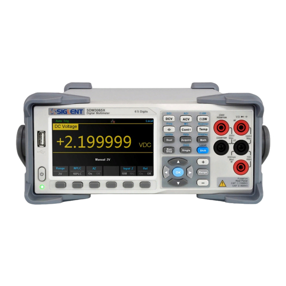
General Features and Specifications SDM3065X is a multimeter designed with 6½ digit reading resolution and dual-display suited for any application requiring high-precision, multifunction, and automated measurements. It features a combination of basic measurement, multiple math, and display functions, etc. General Features ... -
Page 8: Specifications
Specifications DC Characteristics Accuracy ± (% of reading + % of range) Test 24Hour 1Year Temperature ℃ ± 5℃ Current TCAL℃ ± 1℃ ℃ ± 5℃ coefficient Function Range ℃-5℃ ) 0℃to ( Burden ℃+5℃) to 50℃ ( Voltage 200.0000 0.0020+ 0.0015 0.0030 + 0.0020 0.0040 + 0.0023... - Page 9 [5] When Power Supply of frequency is 60 Hz, the cycles is 0.006, 0.06, 0.6,1,10,100 NPLC. SFDR & SINAD Spurious-Free Signal-to-Noise-and-Distortion Function Range Dynamic Range (SFDR) (SINAD) 200 mV 20 V 200 V 1000 V 200 uA SDM3065X Service Manual 3...
- Page 10 2 mA 20 mA 200 mA [1] Typical value. -1 dBFS, 1 kHz single tone. 100 us aperture time and auto zero off. AC Characteristics Accuracy ± (% of reading + % of range) 90 Day Temperature Frequency 1 Year ℃...
- Page 11 1.10 + 0.10 0.100 + 0.008 10.00000 5 Hz-10 Hz 0.35 + 0.08 0.35 + 0.10 0.35 + 0.10 0.035 + 0.008 10 Hz-5 kHz 0.15 + 0.08 0.15 + 0.10 0.15 + 0.10 0.015 + 0.008 SDM3065X Service Manual 5...
- Page 12 Additional Low Frequency Errors (% of reading) Additional Crest Factor Errors (non-sine wave) AC Filter Error (% of reading) Crest Factor Frequency >3 Hz >20 Hz >200 Hz 10 Hz-20 Hz 0.74 1 - 2 0.05 20 Hz-40 Hz 0.22 2 - 3 40 Hz-100 Hz 0.06...
- Page 13 [1] Specifications are for 90 minutes warm–up and using REL operation. Additional errors may be caused by non–film capacitors. [2] Specifications are the 1% to 110% of range on 2nF range and 10% to 110% of range on all other ranges SDM3065X Service Manual 7...
- Page 14 Temperature Characteristic Accuracy ± (% of Reading) Temperature Type 1 Year coefficient Optimum 0℃ to (TCAL℃ - 5℃) Function Probe Type TCAL℃±5 Range ℃ (TCAL℃ + 5℃)to 50℃ α=0.00385 0.16℃ 0.01℃ (R0 is 49Ω to 2.1 -200℃~660℃ kΩ) 0℃~1820℃ 0.76℃ 0.14℃...
- Page 15 200 Hz 1 s Gate time 0.1 s Frequency and Period 0.01 s 0.001 s Capacitance 100 mF Range [1] 20 V range, 1 kHz input. [2] The measurement period changes with the capacitance under test. SDM3065X Service Manual 9...
-
Page 16: Prepare Information
How to use self-test routine How to recall factory Default settings Fore more detailed information about multimeter operation, please refer to the User Guide for the SDM3065X. Functional check This functional check covers three areas, by which you can verify if the multimeter is working correctly. -
Page 17: Self Test
Display Number Hold Probe Hold Self Test The SDM3065X provides self-test functions, including keyboard Test, LCD Test, Beeper Test and Chip Test. Operating Steps: 1. Press [Shift] > [Utility] > Test /Admin > Board Test 2. To test the keyboard: Select keyboard to enter the key test interface. -
Page 18: Performance Verification
Application Recommended Equipment Zero Offset Verification Keysight 34172B DC Voltage and DC Current Gain Fluke 5522A Verification Siglent SDG2000X Series Function/Arbitrary Frequency Accuracy Verification Waveform Generator AC Voltage and AC Current Fluke 5522A Verification Capacitance Verification Fluke 5522A Performance verification step 1. -
Page 19: Test Considerations
1000 V ± 8 mV 200 Ω ± 8 mΩ 2 kΩ 20 mΩ 20 kΩ 200 mΩ 2 Ω Short 4-wire Ohms 200 kΩ 10 Ω 1 MΩ 100 Ω 10 MΩ 100 Ω 100 MΩ SDM3065X Service Manual 13... -
Page 20: Dc Voltage And Dc Current Gain Verification
DC Voltage and DC Current Gain Verification Input Error from Nominal Voltage Function Range (1 years) -200 mV ± 12.6 μV 200 mV 200 mV -2 V ± 82 μV ± 480 μV 10 V -20 V 20 V DC Volts ±... -
Page 21: Frequency Accuracy Verification
± 750 mV 75 V 100 kHz ± 1.8 V Input Error from Nominal (1 years) Irms Frequency Range 1 kHz ± 0.42 uA 200uA 200uA 10 kHz ± 0.21 uA 20mA 1 kHz 20mA ± 0.042 mA SDM3065X Service Manual 15... -
Page 22: Capacitance Verification
10 kHz ± 0.21mA 1 kHz ± 0.282 mA 1 kHz 200mA ± 0.28 mA 200mA 10 kHz ± 0.9 mA 20mA 1 kHz ± 3.23 mA 1 kHz ± 4.2 mA 10 kHz ± 21 mA 200mA 1 kHz ±... -
Page 23: Calibration Adjusting Procedures
Calibration Adjusting Procedures This chapter explains how to adjust the SDM3065X digital multimeter for optimum operating performance. Only qualified personnel should perform this procedure. Calibration Adjustment Interval The instrument should be calibrated on a regular interval determined by the accuracy requirements of your application. A 1-year interval is adequate for most applications. -
Page 24: Recommended Test Equipment
4-Wire Ohms Calibration Capacitance Calibration Temperature Calibration Recommended Test Equipment The recommended test equipment for the performance calibration is listed below. If the exact instrument is not available, substitute calibration standards of equivalent accuracy. Calibrator: FLUKE 5522A High precision digital multimeter:HP3458A Computer: Windows system, configured with GPIB Instrument Control Devices (like PCI-GPIB), installed the software mentioned below. -
Page 25: Test Considerations
Open the "Calibration.xlsx" in the folder "Calibration", then select the corresponding sheet in the "Calibration.xlsx" according to the function of SDM3065X you want to calibrate. b) Set the output of the calibrator according to the "Output Setting Value" in the table, then record the calibration value (pay attention to the units) of the high precision multimeter in the table. - Page 26 If the "Calibration Value" of the function you want to calibrate is not filled in the table, the calibration script will not work correctly. 3. Connect the Calibrator, PC and SDM3065X digital multimeter as shown below: 1. Connect the FLUKE5522A to the computer with GPIB cable 2.
- Page 27 "Test cable connection diagram" in the Appendix. 6. The calibration result will be prompted after procedure is done. Appendix Test cable connection diagram Message SDM3065X connection FLUKE5522A Note DCV/ACV Calibrate Cable connection:DC/AC voltage Resistance Calibrate Cable connection: Resistance - two-wire compensation SDM3065X Service Manual 21...
- Page 28 Resistance Calibrate Cable connection: Resistance - two-wire no compensation DCI/ACI Calibrate Cable connection: DC/AC current (<3A) DCI/ACI Calibrate Cable connection:DC/AC current (>3A) Resistance Calibrate Cable connection: Resistance - four-wire compensation Resistance Calibrate Cable connection: Resistance - four-wire no compensation Capacitance Calibrate Cable connection: disconnect Remove cable from...
-
Page 29: Assembly Procedures
Assembly Procedures This chapter describes how to remove the major modules from the SDM3065X. To install the removed modules or replace new modules, please follow corresponding operating steps in reverse order. Security Consideration Only qualified personnel should perform the disassembly procedures. - Page 30 Assembly Procedures This chapter describes how to remove the major modules from the SDM3065X multimeter. To install the removed modules or replace new modules, please follow corresponding operating steps in reverse order. Security Consideration Only qualified personnel should perform the disassembly procedures.
-
Page 31: Disassembly Procedures
2. Rotate the handle to the upright position and remove it by pulling outward where it attaches to the case. 3. Unscrew the four captive screws in the rear bezel and remove the foot pad as indicated by the arrow shown below SDM3065X Service Manual 25... - Page 32 4. Remove the screw on the bottom of the instrument and place it in a safe location for re-assembly. Slide off the instrument cover as indicated by the arrow shown below.
- Page 33 5. Remove the cable plug(in the red circle and yellow box shown below) connected to the main body 6. Unscrew the 5 captive screws in the rear metal cover and remove the rear metal cover. 7. Unscrew the 4 screws and remove the fan. SDM3065X Service Manual 27...
- Page 34 8. Remove the cable plug connected to the front pannel. 9. Remove the cable and unscrew all the screws,then you can remove thePCBA. This concludes the disassembly procedure. To re-assemble the instrument, reverse the procedure.
-
Page 35: Troubleshooting
SDM3065X digital multimeter. ESD Precautions While performing any internal test of the multimeter, please refer to the following precautions to avoid damages to its internal modules or components resulting from ESD. -
Page 36: Analog Board Drawing
Analog Board Drawing The analog board is a signal sampling board that converts the analog input into a digital signal. Please refer to the following drawing to quickly locate the test points on the analog board for easy resolution of the failures you encounter. -
Page 37: Main Board Drawing
Power Board Drawing The main function of the power board is to convert the AC voltage to DC voltage and supply power to the analog board and main board. SDM3065X Service Manual 31... -
Page 38: Check The Power Supply
Otherwise, it proves to be faulted, please return it to the factory to have it repaired or contact SIGLENT. Note: The main power supply provides an input fuse to protect against the... -
Page 39: Check The Analog Board
Table 6-4 Test DC voltages of the analog board Test point Name Test pin Voltage value (V) Error limit (V) 0 (GND) 1 or 2 +3.3 ± 0.2 1 or 2 ± 0.2 1 or 2 ± 0.2 ± 0.5 ± 0.5 SDM3065X Service Manual 33... -
Page 40: Analog Board Clock Check
5-6, it proves to be faulted, please return it to the factory to have it repaired or contact SIGLENT. Table 6-6 Test DC voltages of the main board Test point Name Voltage value (V) Error limit (V) ±... -
Page 41: Microprocessor Check
(4) Check the connection between the power supply and the main board. (5) If the instrument still does not work normally, please contact SIGLENT. 2. The instrument starts up with a dark screen: (1) Check the connection between the keypad circuit board and the main board. -
Page 42: Maintenance
In no case shall SIGLENT be liable for indirect, special or consequential damages. Repackaging for Shipment If the unit needs to be shipped to SIGLENT for service or repair, be sure: 1. Attach a tag to the unit identifying the owner and indicating the required service or repair. -
Page 43: Contact Siglent
District, Baoan District, Shenzhen, P.R. China Tel:0086-755-3688 7876 E-mail: sales@siglent.com http://www.siglent.com SIGLENT Technologies America, Inc Address: 6557 Cochran Rd Solon, Ohio 44139 E-mail: info@siglent.com http://www.siglentamerica.com SIGLENT Technologies EuropeGmbH Address: Liebigstrasse 2-20, Gebaeude 14, 22113 Hamburg Germany E-Mail: info-eu@siglent.com http://www.siglenteu.com SDM3065X Service Manual 37...
Need help?
Do you have a question about the SDM3065X and is the answer not in the manual?
Questions and answers