
Related Manuals for Rangemaster elan 90 dual fuel


Summary of Contents for Rangemaster elan 90 dual fuel
-
Page 1: User Guide
Britain’s No.1 Range Cooker USER GUIDE & INSTALLATION INSTRUCTIONS Elan 90 Dual Fuel... - Page 2 We o er cookware to work perfectly with all fuel types manufactured by Rangemaster, including induction hobs. You can be assured of functionality with style, as well as the quality and meticulous attention to detail you expect from the pioneers of range cooking.
-
Page 3: Table Of Contents
Contents Before You Start... Troubleshooting Important! Installation Installation and Maintenance Dear Installer Peculiar Smells Safety Requirements and Regulations If You Smell Gas Provision of Ventilation Ventilation Location of Cooker Personal Safety Conversion Cooker Care Positioning the Cooker Cleaning Moving the Cooker Cooker Overview Completing the Move Hotplate Burners... -
Page 5: Before You Start
1. Before You Start... If You Smell Gas Your cooker should give you many years of trouble-free cooking if installed and operated correctly. It is important • DO nOT turn electric switches on or off that you read this section before you start, particularly if you •... -
Page 6: Cooker Care
Always be certain that the controls are in the OFF position Foods for frying should be as dry as possible. Frost on frozen when the oven is not in use, and before attempting to clean foods or moisture on fresh foods can cause hot fat to bubble the cooker. -
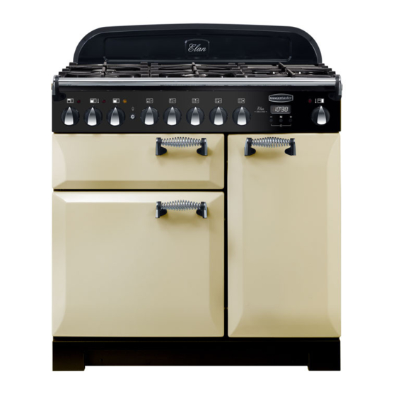
Page 7: Cooker Overview
2. Cooker Overview DocAUS.020-0003 - Overview - 90DF - Elan Fig.2-1 ºC ArtNo.215-0044 - 90 Elan induction The 90 dual fuel cooker (Fig.2-1) has the following features: Fig.2-2 5 hotplate burners including a wok burner A control panel A glide-out grill Main multi-function oven Tall fan oven... -
Page 8: Wok Burner
If, when you let go of the control knob, the burner goes out, Fig.2-3 then the FSD has not been bypassed. Turn the control knob to the OFF position and wait for one minute before you try again, this time making sure to hold in the control knob for slightly longer. -
Page 9: The Wok Cradle
The Wok Cradle Fig.2-9 The wok cradle is designed to t a 35 cm wok. If you use a di erent wok, make sure that it ts the cradle. Woks vary very widely in size and shape. It is important that the wok sits down on the pan support –... -
Page 10: The Glide-Out Grill
The Glide-out Grill Fig.2-15 Open the door and pull the grill pan carriage forward using the handle (Fig.2-15). The grill has two elements that allow either the whole area of the pan to be heated or just the right-hand half. Adjust the heat to suit by turning the control knob. -
Page 11: The Ovens
Fan Oven The Ovens This function operates the fan and the heating The clock must be set to the time of day before the ovens element around it. An even heat is produced will work. See the following section on ‘The Clock’ for throughout the oven, allowing you to cook large instructions on setting the time of day. -
Page 12: Operating The Ovens
half of the oven to cook. The oven temperature may also need Fig.2-18 to be lowered. Browning Element This function uses the element in the top of the oven only. It is a useful function for the browning or nishing of pasta dishes, vegetables in sauce, shepherds pie and lasagne, the item to be browned being already hot before switching to the top element. -
Page 13: The Clock
The Clock Fig.2-22 ArtNo.300-0004 2-button clock annotated You can use the timer (Fig.2-22) to turn the ovens on and o . The clock must be set to the time of day before the ovens will work. Note: When using the timer functions, rst set the clock as required before setting the oven temperature and selecting the oven function (multi-function ovens only). -
Page 14: Manual Cooking
Turn the Timer knob to the [D] position (Fig.2-27). Fig.2-27 Fig.2-28 Use the Adjusting knob to set the ‘cook time’ you need ArtNo.301-0010 2BC ArtNo.301-0009 2BC (Fig.2-28). Setting the cooking time Setting the cooking timer Turn the Timer knob to the [E] position. The display will show the current time of day plus the ‘cook time’... -
Page 15: Accessories
Accessories Fig.2-35 Flat shelf Oven Shelves – Left-hand (Main) Oven Shelf guard In addition to a at shelf, your cooker is supplied with a drop shelf (Fig.2-35). The drop shelf increases the possibilities for oven shelf spacing. Front The oven shelves can be easily removed and re tted. Shelf guard Pull the shelf forward until the back of the shelf is stopped by Drop shelf... -
Page 16: Cooking Tips
3. Cooking Tips Tips on Cooking with the Timer General Oven Tips If you want to cook more than one dish, choose dishes that The wire shelves should always be pushed rmly to the back require approximately the same cooking time. However, of the oven. -
Page 17: Cooking Table
4. Cooking Table DocNo.031-0004 - Cooking table - electric & fan single cavity The oven control settings and cooking times given in the table below are intended to be used Top (T) AS A GUIDE ONLY. Individual tastes may require the temperature to be altered to provide a preferred result. -
Page 18: Cleaning Your Cooker
5. Cleaning Your Cooker Essential Information Fig.5-1 Isolate the electricity supply before carrying out any thorough cleaning. Allow the cooker to cool. NEVER use paint solvents, washing soda, caustic cleaners, biological powders, bleach, chlorine based bleach cleaners, coarse abrasives or salt. DO NOT mix di erent cleaning products –... -
Page 19: The Griddle
The Griddle Fig.5-5 Always clean the griddle after use. Allow it to cool completely before removing. Immerse the griddle plate in hot soapy water. Use a soft cloth or, for stubborn stains, a nylon washing up brush. Note: If the griddle is washed in a dishwasher then some dishwasher residue may appear on the back. -
Page 20: Ovens
Ovens Fig.5-10 ‘Cook & Clean’ Panels The main oven has panels which have been coated with a special enamel that partly cleans itself. This does not stop all marks on the lining, but helps to reduce the amount of manual cleaning needed. The ‘Cook &... -
Page 21: Cleaning Table
Cleaning Table Cleaners listed (Table 5-1) are available from supermarkets or electrical retailers as stated. For enamelled surfaces use a cleaner that is approved for use on vitreous enamel. Regular cleaning is recommended. For easier cleaning, wipe up any spillages immediately. Hotplate Part Finish... -
Page 22: Troubleshooting
6. Troubleshooting Hotplate ignition or hotplate burners faulty Power failure Is the power on? Is the clock illuminated? In the event of a failure in the electrical supply, remember to reset the clock to make sure that the If not, there maybe something wrong with the power timed oven continues to operate. - Page 23 An oven light is not working Fig.6-1 The bulb has probably burnt out. You can buy a replacement bulb (which is not covered under the warranty) from a good electrical shop. Ask for a 15 W – ArtNo.324-0005 Oven light bulb 230 V lamp, FOR OVENS.
-
Page 24: Installation
INSTALLATION Check the appliance is electrically safe and gas sound when you have nished. 7. Installation Dear Installer In the UK the cooker must be installed in accordance with: Before you start your installation, please complete the details below, so that, if your customer has a problem relating to •... -
Page 25: Location Of Cooker
INSTALLATION Check the appliance is electrically safe and gas sound when you have nished. Checking the Parts: Location of Cooker The cooker may be installed in a kitchen/kitchen diner but 3 pan supports Griddle plate NOT in a room containing a bath or shower. This appliance is designed for domestic cooking only. -
Page 26: Positioning The Cooker
INSTALLATION Check the appliance is electrically safe and gas sound when you have nished. Positioning the Cooker Fig.7-1 ArtNo.090-0009 - 90 2BC cooker min spacings Fig.7-1 shows the minimum recommended distance from the cooker to nearby surfaces. 75 mm 75 mm 650 mm The cooker should not be placed on a base. -
Page 27: Completing The Move
INSTALLATION Check the appliance is electrically safe and gas sound when you have nished. Lowering the Two Rear Rollers Fig.7-5 To adjust the height of the rear of the cooker, rst t a 13 mm spanner or socket wrench onto the hexagonal adjusting nut (Fig.7-5). -
Page 28: Conversion To Another Gas
INSTALLATION Check the appliance is electrically safe and gas sound when you have nished. Conversion to Another Gas Fig.7-10 If the appliance is to be converted to another gas do the conversion at this point. See the conversion section of these instructions and see the instructions in the conversion kit. -
Page 29: Gas Connection
INSTALLATION Check the appliance is electrically safe and gas sound when you have nished. Gas Connection Fig.7-13 This must be in accordance with the relevant standards. The exible hose (not supplied with the cooker) must be in accordance with the relevant standards. Hoses may be purchased at most builders’... -
Page 30: Electrical Connection
INSTALLATION Check the appliance is electrically safe and gas sound when you have nished. Electrical Connection Fig.7-14 The cooker must be installed by a quali ed electrician, in accordance with all relevant British Standards/Codes of Practice (in particular BS 7671), or with the relevant national and local regulations. -
Page 31: Conversion To Lp Gas
WARNING – SERVICING TO BE CARRIED OUT ONLY BY AN AUTHORISED PERSON Disconnect from electricity and gas before servicing. Check appliance is safe when you have nished. 8. Conversion to LP Gas Check the ‘Technical Data’ section at the back of the book Fig.8-1 that the hob is convertible to the gas you want to use. -
Page 32: Stick On Label
WARNING – SERVICING TO BE CARRIED OUT ONLY BY AN AUTHORISED PERSON Disconnect from electricity and gas before servicing. Check appliance is safe when you have finished. Stick on Label Stick the LP gas label over the natural gas part of the appliance data label. -
Page 33: Circuit Diagram
9. Circuit Diagram P095199 P028728 br b The connections shown in the circuit diagram are for single-phase. The ratings are for 230 V 50 Hz. Code Description Code Description Code Colour Grill control Right-hand fan oven thermostat Blue Grill element left-hand side Right-hand fan oven switch Brown Grill element right-hand side... -
Page 34: Technical Data
10. Technical Data ArtNo.105-0008 - Technical data - 90 induction - Elan THE COOKER IS CATEGORY: II 2H3+. It is supplied set for group H natural gas. A conversion kit from NG to LP is packed with the cooker. INSTALLER: Please leave these instructions with the User. DATA BADGE LOCATION: Cooker back, serial number repeater badge below oven door opening. - Page 35 Gas Safe registered engineer for gas appliances or an approved electrician for electrical models. CONSUMER SERVICE For a competitive quote and to arrange for a Rangemaster approved If you have any product enquiries, or in the event of a problem engineer to attend, call Consumer Services on: 0870 7895107.
- Page 36 Registered in England and Wales. Registration No. 354715 Registered O ce: Juno Drive, Leamington Spa, Warwickshire, CV31 3RG Rangemaster continuously seeks improvements in speci cation, design and production of products and thus, alterations take place periodically. Whilst every e ort is made to produce up-to-date literature, this booklet should not be regarded as an infallible guide to...
Need help?
Do you have a question about the elan 90 dual fuel and is the answer not in the manual?
Questions and answers