Table of Contents
Advertisement
Quick Links
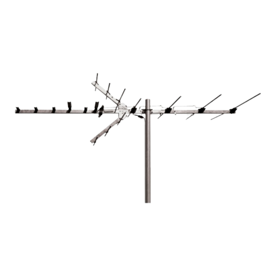
ANT3037X
Outdoor Antenna
Installation Manual
Point Toward Stations
Please read the IMPORTANT SAFETY INFORMATION sheet included in
Installation of this antenna near power lines is dangerous. For your safety,
BEFORE YOU START!!!
this package.
WARNING
follow the installation instructions.
Mast not included
with antenna.
1
Advertisement
Table of Contents

Related Manuals for RCA ANT3037X


Summary of Contents for RCA ANT3037X
-
Page 1: Before You Start
ANT3037X Outdoor Antenna Installation Manual Point Toward Stations Mast not included with antenna. BEFORE YOU START!!! Please read the IMPORTANT SAFETY INFORMATION sheet included in this package. WARNING Installation of this antenna near power lines is dangerous. For your safety,... -
Page 2: Parts List
Parts List Back Assembly (VHF) Front Assembly (UHF) Small Flange Nut (6) Washer (6) Corner Refl ector (2) Large Screw (2) U-Bolt Mast Clamp Insert Large Flange Nut for U-Bolt (2) Matching Transformer Low Band VHF Add-On Kit For RF Channels 2–6 and/or FM (Not Needed for Most Installations, See Page 3.) Large Screw... - Page 3 Things to Consider Before Installing the Antenna Location Selection Digital broadcast signals travel via line of sight. That means the fewer objects between your antenna and the broadcast tower, the stronger your signal will be. Installing your antenna in the attic may reduce the signal by as much as 50%, so it is always recommended to install the antenna outdoors for maximum performance.
-
Page 4: Assembling The Antenna
Assembling the Antenna Start by unfolding the VHF elements on the back assembly until the elements are perpendicular to the boom (Figure 1). You should hear the elements click into place. After Before VHF Elements Boom Boom Figure 1 Unfold the six UHF elements on the front assembly until they are perpendicular to the boom. - Page 5 Slide the crimped end of the front assembly boom into the open end of the back assembly boom (Figure 4). Re-insert the screw into the plastic block closest to the mast clamp, and secure with the fl ange nut. Front Assembly Back Assembly Crimped End Screw...
- Page 6 Insert the open end of one corner refl ector in-between the top of the refl ector brackets (Figure 7). (Elements should be on top.) Align the holes in the brackets with the hole in the corner refl ector. Insert a large screw through the holes.
- Page 7 If you determined that you need the Low Band VHF Add-On Kit, proceed with the steps on the next page. If you determined that you do not need the Low Band VHF Add-On Kit (page 2), continue with attaching the coax cable on page 9.
- Page 8 Insert the large screw through the hole in the bottom of the boom (Figure 11). Place the element extension with crimped ends onto the screw. Then, install the clip onto the element extension with crimped ends so that the holes in both parts align. Thread a small fl ange nut on the screw, and tighten.
- Page 9 Slide the element sleeve over the element. Align the holes in the element sleeve and element. Then, slide the element extension into the element sleeve. Align the holes in the element sleeve and element extension. Insert a small screw through the top of each hole, and thread a small fl ange nut onto each screw.
-
Page 10: Mounting The Antenna
Remove the rubber boot from the matching Rubber Boot transformer. Slide the rubber boot over the coax cable and install the connector. If your Fork coax cable has the connector already on it, you will need to cut an X in the boot hole so that the boot will slide over the connector. - Page 11 Providing Lightning Protection for the Antenna 1. Mount lightning arrestor or 75 ohm grounding block as close as possible to where lead-in enters house. 2. Ground wires for both mast and lead-in should be copper or aluminum wire, number 8 or larger. 3.
- Page 12 The received signal is not strong enough to ensure consistent performance. If you have questions, contact RCA at 1-800-290-6650 or visit RCAAudioVideo.com. Note: We recommend using this antenna with a high quality preamplifi er, such as the RCA TVPRAMP1R, available at many retailers or from RCAAudioVideo.com.
-
Page 13: Troubleshooting
Troubleshooting Issue Possible Cause There is static or snow in the Digital television is all or nothing; the picture. picture is crystal clear, or there isn’t one. Static means there is interference between the digital tuner and the television screen. If you use a digital converter, one of the connections or the cable between the converter and television may be bad, or the channel... - Page 14 U.S.A.: Audiovox Return Center, 150 Marcus Blvd., Hauppauge, NY 11788 CANADA: Audiovox Return Center, c/o Genco, 6685 Kennedy Road, Unit #3 Door 14, Mississauga Ontario L5T 3A5 ©2013 VOXX Accessories Corporation 3502 Woodview Trace, Suite 220, Indianapolis, IN 46268 ANT3037X NA IB 01...
Need help?
Do you have a question about the ANT3037X and is the answer not in the manual?
Questions and answers