Table of Contents
Advertisement
HC-20_US.qxd 14.7.1 9:13 ページ a
INSTALLATION AND OPERATION INSTRUCTIONS
HC-20
MODEL
IMPORTANT
READ AND UNDERSTAND INSTRUCTIONS BEFORE INSTALLING OR USING UNIT.
RETAIN INSTRUCTIONS FOR FUTURE REFERENCE. CHECK LOCAL CODES AND ORDINANCES FOR PERMITTED USE.
····················································· 2
····················································· 4
······················································· 5
HEAT CONVECTOR
················································ 1
································ 3
········································ 4
····································· 5
···························· 6
························· 7
······························· 7
CONTENTS
···················································· 11
····················································· 11
······················································· 14
············································· 16
··················· 8
································ 10
····································· 15
Advertisement
Table of Contents

Related Manuals for Toyotomi HC-20


Summary of Contents for Toyotomi HC-20
-
Page 1: Table Of Contents
HC-20_US.qxd 14.7.1 9:13 ページ a HEAT CONVECTOR INSTALLATION AND OPERATION INSTRUCTIONS HC-20 MODEL IMPORTANT READ AND UNDERSTAND INSTRUCTIONS BEFORE INSTALLING OR USING UNIT. RETAIN INSTRUCTIONS FOR FUTURE REFERENCE. CHECK LOCAL CODES AND ORDINANCES FOR PERMITTED USE. CONTENTS SECTION A: SECTION E: Specifications ················································... -
Page 2: Section A
HC-20_US.qxd 14.7.1 9:13 ページ 1 SECTION A: SPECIFICATIONS Model: HC-20 Type: Hot Water Heating, Floor Standing Type Heat Rating Range: 3,000 to 20,000 BTU/h (0.88 to 5.9 kW) *See the chart below for details. Max. Allowable Pressure: 142 PSI (0.98 MPa) Heat Exchanger Capacity: 0.16 gal. -
Page 3: Section B
HC-20_US.qxd 14.7.1 9:13 ページ 2 SECTION B: UNPACKING UNPACKING 1. Unpack the unit carefully. 2. Check to see if there are any loose screws that may have occurred in transit. 3. Take accessories and the instruction manual out of the carton. ACCESSORY PARTS 1. -
Page 4: Section C
HC-20_US.qxd 14.7.1 9:13 ページ 3 SECTION C: SAFETY TIPS FOR INSTALLATION The instructions which are contained in this manual are classified into the following two types, which are “WARNING” and “CAUTION”. These instructions are intended to provide important information for safe operation. “WARNING”... -
Page 5: Section D
HC-20_US.qxd 14.7.1 9:13 ページ 4 SECTION D: INSTALLATION WARNING: This unit must be installed in accordance with these instructions, local codes, ordinances and/or in the absence of local codes National Plumbing standards. Check and comply with all state and local codes before beginning the installation. This unit should be installed by a licensed, authorized person(s) due to the necessity of making electrical and water connections. -
Page 6: Plumbing
HC-20_US.qxd 14.7.1 9:13 ページ 5 PLUMBING NOTE: Make sure the piping for the unit is laid out properly, and also check for any water leakage. 1. Install heat insulation material on the water piping to prevent heat loss. 2. Copper or polyethylene pipe should be used for connecting pipes. 3. -
Page 7: Permanent Wiring Installation
HC-20_US.qxd 14.7.1 9:13 ページ 6 PERMANENT WIRING INSTALLATION WARNING: TO AVOID ANY RISK OF FIRE AND ELECTRIC SHOCK. Make sure the Main circuit breaker and power supply cord is disconnected before servicing. Electric shock may cause serious injury. It is recommended that installation should be conducted by a Licensed Electrician. -
Page 8: External Output Terminal Wiring
HC-20_US.qxd 14.7.1 9:13 ページ 7 EXTERNAL OUTPUT TERMINAL WIRING This unit has an External output terminal for low-voltage (24 volts or less) contacts to connected to a circulation pump control or zone valve. When connecting the circulation control or zone valve unit to this terminal, it is possible to stop the circulation by the output from internal contact switch in the Heat convector. -
Page 9: Section E
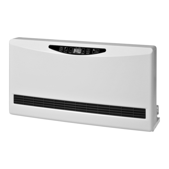
HC-20_US.qxd 14.7.1 9:13 ページ 8 SECTION E: OPERATING CONTROLS AND PART NAMES Air release screw Operation panel External output Front panel (for circulation control or zone valve) Air filter Junction box 12. Thermistor Louvers (Room Temperature) Water supply (NPT 1/2 female) Water return (NPT 1/2 female) 6. - Page 10 HC-20_US.qxd 14.7.1 9:13 ページ 9 POWER switch: Main switch turns the unit on or off. 2. AUTO/MANUAL button: Button switches fan speed to either AUTO and MANUAL. TIMER button: Button turns Timer operation mode on or off. CHILD LOCK button: The button turns CHILD LOCK operation mode on or off.
-
Page 11: Section F
HC-20_US.qxd 14.7.1 9:13 ページ 10 SECTION F: SAFETY TIPS FOR OPERATION The instructions which are contained in this manual are classified into the following two types, which are “WARNING” and “CAUTION”. These instructions are intended to provide important information for safe operation. “WARNING”... -
Page 12: Section G
HC-20_US.qxd 14.7.1 9:13 ページ 11 SECTION G: OPERATION BEFORE USE 1. Position of the Unit Make sure the position of the unit is level. 2. Plug in the Unit Plug unit into a 120V AC electrical outlet. On digital display will appear two sets of dashes. - Page 13 HC-20_US.qxd 14.7.1 9:13 ページ 12 C. When room temperature exceeds the selected setting by approx. 4˚F (2˚C), the Fan will automatically stop. As room temperature drops, the Fan will automatically re-start to maintain the desired temperature. NOTE: Initial setting of the temperature is Fahrenheit. If you like to change to Celsius, contact your dealer. 2.
- Page 14 HC-20_US.qxd 14.7.1 9:13 ページ 13 Example: Your normal room temperature is set for 70 degrees. You work 70˚F 70˚F (Ordinary set temp.) (Ordinary set temp) from 8 am until 5 pm. You want the room temperature to drop to 62 degrees while you are at work and you want the room to 62˚F return to 70 degrees at 4 pm so it will be warm when you get Press...
-
Page 15: Section H
HC-20_US.qxd 14.7.1 9:13 ページ 14 SECTION H: TEST RUN PREPARATION 1. Make sure there is no water leaking from the unit and piping. 2. Make sure electrical connections and grounding are wired properly. 3. Check for air trapped in the plumbing. OPERATION 1. -
Page 16: Section I
HC-20_US.qxd 14.7.1 9:13 ページ 15 SECTION I: ROUTINE MAINTENANCE CAUTION: Be sure to unplug the unit before performing any checks or cleaning. FOR OPTIMUM UNIT PERFORMANCE, THE PARTS SHOWN BELOW SHOULD BE CLEANED REGULARLY: 1. Clean Louvers (ONCE A MONTH) Dust and stains should be wiped off louvers with a damp cloth. -
Page 17: Section J
HC-20_US.qxd 14.7.1 9:13 ページ 16 SECTION J: TROUBLESHOOTING PLEASE NOTE THE FOLLOWING BEFORE REQUESTING FOR HELP FOR REPAIR AND SERVICES The following conditions can happen during operation of the unit. CONDITION REASON - Power outage. Does not operate. - Power supply cord is disconnected. - Child Lock is on. -
Page 18: Limited Warranty
WHO IS COVERED : The original purchaser at retail. WHAT WE WILL DO : TOYOTOMI will either repair or replace, at its option, all defective parts free of charge that are covered by this limited warranty on a carry-in basis, to your nearest authorized dealer or distributor of TOYOTOMI.
Need help?
Do you have a question about the HC-20 and is the answer not in the manual?
Questions and answers