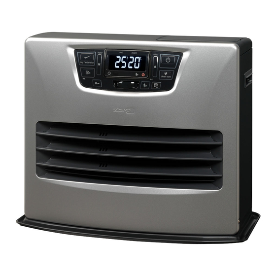
Toyotomi Laser 300 Service Manual
Laser vented heating system
Hide thumbs
Also See for Laser 300:
- Installation and operation instruction manual (36 pages) ,
- Service manual (60 pages)

Related Manuals for Toyotomi Laser 300


Summary of Contents for Toyotomi Laser 300
- Page 1 VENTED HEATER SERVICE MANUAL Laser 300 (TypeA) Laser 530 (TypeA) Laser 560 (TypeA) Laser 730 (TypeA)
-
Page 2: Table Of Contents
L A S E R H E A T I N G S Y S T E M S Table of Contents Section 1 Description Page 1-8 Introduction 1-26 Fuel Delivery System Physical Specifications 1-27 Electrical System Description of Functions 1-28 Safety Mechanisms Description... -
Page 3: Introduction
W × D × H (inches) Weight Hole • A cabinet • A forced flue venting system 17-3/8” × 21-3/4” × 15-1/8” 31 lbs. Laser 300 (440 × 555 × 385 mm) (14kg) • A combustion system • An air circulation system 19-5/8” × 23-5/8” × 16-1/2” 38 lbs. 2-3/4 Laser 530 •... -
Page 4: Description
The blower motor assembly on Laser 560/730 is a dual mounting posts within the burner. function fan with the intake air and exhaust air fans Laser 300: 20479543 Laser 530: 20478343 mounted on a common shaft. Inside of the blower case Laser 560: 20478343 Laser 730: 20478643 are separated into two compartments by a sealed plate. - Page 5 See Fig. 1-2. Laser 300: 20470219 Laser 530: 20470319 Laser 300/Laser 530/Laser 560/Laser 730: 20470234 Laser 560: 20470419 Laser 730: 20470619...
-
Page 6: Burne
The heater will start with normal operation. temperatures, the exhaust pipe will become hot Laser 300/Laser 530/Laser 560/Laser 730: 20470206 during operation. The insulating cloth cover protects the user from accidental contact burn with these hot 1-23 Pressure Relief Plate metal surfaces. - Page 7 L A S E R H E A T I N G S Y S T E M S Section 1 Description Model Laser 530 1-25 Forced Flue Venting System The forced flue venting system channels air to and from the heater.
-
Page 8: Power Failure Recovery System
L A S E R H E A T I N G S Y S T E M S Section 1 Description due to power failure. The time, however, is stored by the cycle, before turning back on. The circulation fan motor will remain on during this time. -
Page 9: Error Codes History
L A S E R H E A T I N G S Y S T E M S Section 1 Description ON or the unit comes back on from a power failure, the normal operation push these buttons again at the same operation lamp will flash (0.5 Hz) and both the blower time for 3 seconds, the unit will then shift back to the motor and circulation fan motor will turn to high... - Page 10 L A S E R H E A T I N G S Y S T E M S Section 1 Description seconds. The display will show “AL Hi”, flash for 3 times, When Fuel Pump Level is at “L 1” condition, a beep and then shift to off mode.
-
Page 11: Routine Maintenance
L A S E R H E A T I N G S Y S T E M S Section 2 Routine Maintenance At the time of the demonstration or installation, heater Introductlon maintenance should be discussed with the user; Heater maintenance is divided into two classifications;... - Page 12 L A S E R H E A T I N G S Y S T E M S Section 2 Routine Maintenance ACTIVITY MATERIAL REMARKS Inspect the burner ring, and the flame Clean all carbon deposits. Replace if sensor. excessively warped or cracked.
-
Page 13: Flame Rod Sensor
Failed ignition. How to replace/attach the burner matts; n Failure to maintain combustion. n Noise from the blower motor. For Laser 300 Fuel nozzle Place the edge of rectangular burner Fig. A mat (Part # 20479513) under the fuel... -
Page 14: Removal Of Water Deposits And
L A S E R L A S E R H E A T I N G H E A T I N G S Y S T E M S S Y S T E M S Section 3 Servicing NOTE: A water block fuel filter is recommended on the... -
Page 15: Lines
L A S E R L A S E R H E A T I N G H E A T I N G S Y S T E M S S Y S T E M S Section 3 Servicing STEP 3: Reassembly of Heater Inspect Intake/Exhaust Air Lines... -
Page 16: Filter
L A S E R L A S E R H E A T I N G H E A T I N G S Y S T E M S S Y S T E M S Section 3 Servicing STEP 2: Inspection and Cleaning 3-10... -
Page 17: Blower Motor Assembly
L A S E R L A S E R H E A T I N G H E A T I N G S Y S T E M S S Y S T E M S Section 3 Servicing 3-11 Cleaning Blower Motor (Only Laser 560/730) - Page 18 L A S E R H E A T I N G S Y S T E M S Section 3 Servicing Burner thermistor temperature indication Display ºC Display ºC Display ºC Display ºC Display ºC Display ºC — 137.9 108.9 88.0 66.4...
- Page 19 L A S E R H E A T I N G S Y S T E M S Section 3 Servicing Flame electric current value indication μA μA μA μA μA μA more than S E R V I C E M A N U A L...
- Page 20 S E R V I C E M A N U A L...
- Page 21 L A S E R H E A T I N G S Y S T E M S Section 4 Trouble Shooting Electrical System S E R V I C E M A N U A L...
-
Page 22: Resistor/Capacitor Value
L A S E R H E A T I N G S Y S T E M S Section 4 Trouble Shooting Resistor/Capacitor Value Resistor Value Laser COMPONENT Laser300 Laser530 Laser560 730/730AT Igniter at cold condition (73°F(23°)) 17Ω±10% Primary Side 1 to 3 3.7Ω±30% Secondary Side 5 to 6 0.6Ω±30%... - Page 23 S Y S T E M S Section 4 Trouble Shooting Control Circuit Board Time Chart MA-252 series LASER 300 / LASER 530 / LASER 560 / LASER 730 A: LASER 300 / LASER 530 B: LASER 560 / LASER 730 Item Specification Conditions...
- Page 24 L A S E R L A S E R H E A T I N G H E A T I N G S Y S T E M S S Y S T E M S Section 4 Trouble Shooting Control Circuit Board Time Chart...
-
Page 25: Trouble Shooting
L A S E R L A S E R H E A T I N G H E A T I N G S Y S T E M S S Y S T E M S Section 4 Trouble Shooting Control Circuit Board Time Chart... - Page 26 L A S E R L A S E R H E A T I N G H E A T I N G S Y S T E M S S Y S T E M S Section 4 Trouble Shooting Control Circuit Board Time Chart...
- Page 27 L A S E R L A S E R H E A T I N G H E A T I N G S Y S T E M S S Y S T E M S Section 4 Trouble Shooting Control Circuit Board Time Chart...
- Page 28 L A S E R L A S E R H E A T I N G H E A T I N G S Y S T E M S S Y S T E M S Section 4 Trouble Shooting Control Circuit Board Time Chart...
- Page 29 L A S E R L A S E R H E A T I N G H E A T I N G S Y S T E M S S Y S T E M S Section 4 Trouble Shooting Control Circuit Board Time Chart...
- Page 30 L A S E R L A S E R H E A T I N G H E A T I N G S Y S T E M S S Y S T E M S Section 4 Trouble Shooting Control Circuit Board Time Chart...
- Page 31 L A S E R L A S E R H E A T I N G H E A T I N G S Y S T E M S S Y S T E M S Section 4 Trouble Shooting Control Circuit Board Time Chart...
- Page 32 L A S E R L A S E R H E A T I N G H E A T I N G S Y S T E M S S Y S T E M S Section 4 Trouble Shooting Control Circuit Board Time Chart...
- Page 33 L A S E R L A S E R H E A T I N G H E A T I N G S Y S T E M S S Y S T E M S Section 4 Trouble Shooting Control Circuit Board Time Chart...
- Page 34 L A S E R L A S E R H E A T I N G H E A T I N G S Y S T E M S S Y S T E M S Section 4 Trouble Shooting Control Circuit Board Time Chart...
- Page 35 L A S E R H E A T I N G S Y S T E M S Section 4 Trouble Shooting GENERAL CHECKS Is power available in wall outlet? Is ON/OFF switch on? Is power plug inserted in wall outlet? Is operation mode on “MANUAL”? Has there been a power interruption? Is set temperature in “HIGH”...
- Page 36 L A S E R H E A T I N G S Y S T E M S Section 4 Trouble Shooting FAILURE CHECK1 RESULT CHECK2 RESULT CHECK3 RESULT CHECK4 RESULT CHECK5 RESULT CAUSE SOLUTION Flame rod sensor touches burner Correct or change flame rod sensor Stops Does ignite?
- Page 37 L A S E R H E A T I N G S Y S T E M S Section 4 Trouble Shooting FAILURE CHECK1 RESULT CHECK2 RESULT CHECK3 RESULT CHECK4 RESULT CHECK5 RESULT CAUSE SOLUTION Flame rod sensor touches burner Stops Does flame Correct or change flame rod sensor...
- Page 38 L A S E R H E A T I N G S Y S T E M S Section 4 Trouble Shooting FAILURE CHECK1 RESULT CHECK2 RESULT CHECK3 RESULT CHECK4 RESULT CHECK5 RESULT CAUSE SOLUTION Clean fan cover Is window Yes.
-
Page 39: Room Temperature Sensor
L A S E R H E A T I N G S Y S T E M S Section 4 Trouble Shooting FAILURE CHECK1 RESULT CHECK2 RESULT CHECK3 RESULT CHECK4 RESULT CHECK5 RESULT CAUSE SOLUTION Does blower Is a unit Yellow high Normal Normal... - Page 40 H E A T I N G S Y S T E M S S Y S T E M S Section 4 Trouble Shooting Laser 300 Parts Description S E R V I C E M A N U A L...
-
Page 41: Fuse
H E A T I N G H E A T I N G S Y S T E M S S Y S T E M S Section 4 Trouble Shooting Laser 300 Parts Description REF # PART # PART NAME REF #... - Page 42 L A S E R L A S E R H E A T I N G H E A T I N G S Y S T E M S S Y S T E M S Section 4 Trouble Shooting Laser 530 Parts Description...
-
Page 43: Pressure Relief Plate
L A S E R L A S E R H E A T I N G H E A T I N G S Y S T E M S S Y S T E M S Section 4 Trouble Shooting Laser 530 Parts Description... - Page 44 L A S E R L A S E R H E A T I N G H E A T I N G S Y S T E M S S Y S T E M S Section 4 Trouble Shooting Laser 560 Parts Description...
- Page 45 L A S E R L A S E R H E A T I N G H E A T I N G S Y S T E M S S Y S T E M S Section 4 Trouble Shooting Laser 560 Parts Description...
- Page 46 L A S E R L A S E R H E A T I N G H E A T I N G S Y S T E M S S Y S T E M S Section 4 Trouble Shooting Laser 730 / Laser 730 AT Parts Description...
- Page 47 L A S E R L A S E R H E A T I N G H E A T I N G S Y S T E M S S Y S T E M S Section 4 Trouble Shooting Laser 730 / Laser 730 AT Parts Description...
- Page 48 TOYOTOMI U.S.A., INC. 604 Federal Road, Brookfield, CT 06804 www.toyotomiusa.com New 11/15 Part #B1500021 Printed in Japan...
Need help?
Do you have a question about the Laser 300 and is the answer not in the manual?
Questions and answers