Mitsubishi Electric SEZ-KD25VA Service Manual
Split-type, heat pump air conditioners
Hide thumbs
Also See for SEZ-KD25VA:
- Operation manual (18 pages) ,
- Installation manual (16 pages) ,
- Manual (118 pages)
Table of Contents
Advertisement
Advertisement
Table of Contents
Troubleshooting

Related Manuals for Mitsubishi Electric SEZ-KD25VA


Summary of Contents for Mitsubishi Electric SEZ-KD25VA
- Page 1 SPLIT-TYPE, HEAT PUMP AIR CONDITIONERS 2012 TECHNICAL & SERVICE MANUAL Series SEZ Model name Model name <Indoor unit> <Indoor unit> SEZ-KD25VA(L) SEZ-KD35VA(L) SEZ-KD50VA(L) SEZ-KD60VA(L) SEZ-KD71VA(L) INDOOR UNIT TEMP ON/OFF TEMP. ON/OFF WIRED REMOTE WIRELESS REMOTE CONTROLLER CONTROLLER...
-
Page 3: Table Of Contents
CONTENTS 1. PART NAMES AND FUNCTIONS ···········································································2 2. SPECIFICATIONS ···································································································5 3. OUTLINES AND DIMENSIONS·············································································18 4. WIRING DIAGRAM ································································································20 5. REFRIGERANT SYSTEM DIAGRAM····································································21 6. TROUBLESHOOTING ···························································································22 7. DISASSEMBLY PROCEDURE··············································································34... -
Page 4: Part Names And Functions
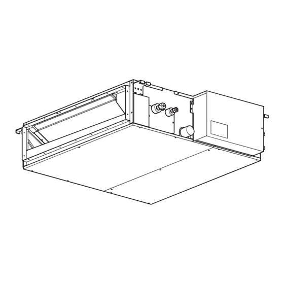
PART NAMES AND FUNCTIONS Indoor Unit SEZ-KD25VA(L) SEZ-KD35VA(L) SEZ-KD50VA(L) SEZ-KD60VA(L) SEZ-KD71VA(L) Air outlet Air outlet duct flange Air inlet Wired remote controller Once the controls are set, the same operation mode can be repeated by simply pressing the ON/OFF button. - Page 5 ● Display “Sensor” indication Displayed when the remote controller sensor is used. Day-of-Week For purposes of this explanation, Shows the current day of the week. all parts of the display are shown as lit. During actual operation, only Time/Timer Display the relevant items will be lit.
-
Page 6: Wireless Remote Controller
Wireless remote controller ● Operation buttons CHECK TEST RUN SET TEMPERATURE button ON/OFF button MODEL SELECT SET TEMPERATURE button sets and Pushing button starts operation. any desired room temperature. Pushing again stops operation. NOT AVAILABLE TEMP ON/OFF AUTO STOP/AUTO START button FAN SPEED button Used for selecting timed starting or st- This button is used to set fan speed to... -
Page 7: Specifications
SPECIFICATIONS SEZ-KD25VA(L) SEZ-KD35VA(L) Model Name Operation Mode Cooling Heating Cooling Heating Power source 220 - 240V (50/60Hz) 220 - 240V (50/60Hz) Power input 0.04 0.05 Current 0.39 0.46 Temperature set range Remote controller ˚ C( ˚ F) 19 to 30 (67 to 86) -
Page 8: 50/60Hz
SEZ-KD50VA(L) SEZ-KD60VA(L) Model Name Operation Mode Cooling Heating Cooling Heating Power source 220 - 240V (50/60Hz) 220 - 240V (50/60Hz) Power input 0.07 0.07 Current 0.63 0.63 Temperature set range Remote controller ˚ C( ˚ F) 19 to 30 (67 to 86) 17 to 28 (63 to 83) 19 to 30 (67 to 86) 17 to 28 (63 to 83) -
Page 9: 50/60Hz
SEZ-KD71VA(L) Model Name Operation Mode Cooling Heating Power source 220 - 240V (50/60Hz) Power input 0.10 Current 0.84 Temperature set range Remote controller ˚ C( ˚ F) 19 to 30 (67 to 86) 17 to 28 (63 to 83) Airflow direction Sirocco fan x 4 Type x Quantity External static press... - Page 10 NOISE CRITERION CURVES <50/60Hz> <50/60Hz> SEZ-KD25VA(L) SEZ-KD25VA(L) NOTCH LINE NOTCH LINE SPL(dB) SPL(dB) External static pressure: 5Pa High External static pressure: 15Pa High Middle Middle NC-70 NC-70 NC-60 NC-60 NC-50 NC-50 NC-40 NC-40 NC-30 NC-30 APPROXIMATE APPROXIMATE TERESHOLD OF TERESHOLD OF...
- Page 11 <50/60Hz> <50/60Hz> SEZ-KD35VA(L) SEZ-KD35VA(L) NOTCH SPL(dB) LINE NOTCH SPL(dB) LINE High High External static pressure: 5Pa External static pressure: 15Pa Middle Middle NC-70 NC-70 NC-60 NC-60 NC-50 NC-50 NC-40 NC-40 NC-30 NC-30 APPROXIMATE APPROXIMATE TERESHOLD OF TERESHOLD OF HEARING FOR HEARING FOR NC-20 NC-20...
- Page 12 <50/60Hz> <50/60Hz> SEZ-KD50VA(L) SEZ-KD50VA(L) NOTCH SPL(dB) LINE NOTCH SPL(dB) LINE High High External static pressure: 5Pa External static pressure: 15Pa Middle Middle NC-70 NC-70 NC-60 NC-60 NC-50 NC-50 NC-40 NC-40 NC-30 NC-30 APPROXIMATE APPROXIMATE TERESHOLD OF TERESHOLD OF HEARING FOR HEARING FOR NC-20 NC-20...
- Page 13 <50/60Hz> <50/60Hz> SEZ-KD60VA(L) SEZ-KD60VA(L) NOTCH SPL(dB) LINE NOTCH SPL(dB) LINE High High External static pressure: 5Pa External static pressure: 15Pa Middle Middle NC-70 NC-70 NC-60 NC-60 NC-50 NC-50 NC-40 NC-40 NC-30 NC-30 APPROXIMATE APPROXIMATE TERESHOLD OF TERESHOLD OF HEARING FOR HEARING FOR NC-20 NC-20...
- Page 14 <50/60Hz> <50/60Hz> SEZ-KD71VA(L) SEZ-KD71VA(L) NOTCH SPL(dB) LINE NOTCH SPL(dB) LINE High High External static pressure: 5Pa External static pressure: 15Pa Middle Middle NC-70 NC-70 NC-60 NC-60 NC-50 NC-50 NC-40 NC-40 NC-30 NC-30 APPROXIMATE APPROXIMATE TERESHOLD OF TERESHOLD OF HEARING FOR HEARING FOR NC-20 NC-20...
-
Page 15: Middle
INDOOR FAN PERFORMANCE AND CORRECTED AIR FLOW SEZ-KD25VA(L) SEZ-KD25VA(L) (External static pressure 5Pa) 220-240V 50/60Hz (External static pressure 15Pa) 220-240V 50/60Hz Limit Limit High Middle High Rated point Middle Rated point Airflow rate(m /min) Airflow rate(m /min) SEZ-KD25VA(L) SEZ-KD25VA(L) (External static pressure 35Pa) 220-240V 50/60Hz... -
Page 16: 50/60Hz
SEZ-KD35VA(L) SEZ-KD35VA(L) (External static pressure 5Pa) 220-240V 50/60Hz (External static pressure 15Pa) 220-240V 50/60Hz Limit Limit High High Middle Rated point Middle Rated point Airflow rate(m /min) Airflow rate(m /min) SEZ-KD35VA(L) SEZ-KD35VA(L) (External static pressure 35Pa) 220-240V 50/60Hz (External static pressure 50Pa) 220-240V 50/60Hz Limit Limit Rated point... -
Page 17: 50/60Hz
SEZ-KD50VA(L) SEZ-KD50VA(L) (External static pressure 5Pa) 220-240V 50/60Hz (External static pressure 15Pa) 220-240V 50/60Hz Limit Limit High High Middle Middle Rated point Rated point Airflow rate(m /min) Airflow rate(m /min) SEZ-KD50VA(L) SEZ-KD50VA(L) (External static pressure 35Pa) 220-240V 50/60Hz (External static pressure 50Pa) 220-240V 50/60Hz Limit Limit High... -
Page 18: Middle
SEZ-KD60VA(L) SEZ-KD60VA(L) (External static pressure 5Pa) 220-240V 50/60Hz (External static pressure 15Pa) 220-240V 50/60Hz Limit Limit High Middle High Middle Rated point Rated point Airflow rate(m /min) Airflow rate(m /min) SEZ-KD60VA(L) SEZ-KD60VA(L) (External static pressure 35Pa) 220-240V 50/60Hz (External static pressure 50Pa) 220-240V 50/60Hz Limit Limit High... -
Page 19: Middle
SEZ-KD71VA(L) SEZ-KD71VA(L) (External static pressure 5Pa) 220-240V 50/60Hz (External static pressure 15Pa) 220-240V 50/60Hz Limit Limit High Rated point High Middle Middle Rated point Airflow rate(m /min) Airflow rate(m /min) SEZ-KD71VA(L) SEZ-KD71VA(L) (External static pressure 35Pa) 220-240V 50/60Hz (External static pressure 50Pa) 220-240V 50/60Hz Limit High Limit... -
Page 20: Outlines And Dimensions
OUTLINES AND DIMENSIONS SEZ-KD25VA(L) Unit : mm SEZ-KD35VA(L) SEZ-KD50VA(L) SEZ-KD60VA(L) SEZ-KD71VA(L) 157.5 37 100 outlet inlet L-{2.9 2XE-{2.9 Air filter 625 (Suspension bolt pitch) Knockout hole {27 Suspension bolt hole (Remote controller transmission line) 4-14X30 Slot 2 Refrigerant piping flare connection (liquid) - Page 21 SEZ-KD25VA(L) SEZ-KD35VA(L) SEZ-KD50VA(L) SEZ-KD60VA(L) SEZ-KD71VA(L) Secure enough access space to allow for the maintenance, inspection, and replacement of the motor, fan, drain pump, heat exchanger, and electric box in one of the following ways. Select an installation site for the indoor unit so that its maintenance access space will not be obstructed by beams or other objects.
-
Page 22: Wiring Diagram
WIRING DIAGRAM SEZ-KD25VA(L) SEZ-KD35VA(L) SEZ-KD50VA(L) SEZ-KD60VA(L) SEZ-KD71VA(L) INSIDE SECTION OF CONTROL BOX TB15 TO MA REMOTE CONTROLLER I.B. ✻ For SEZ-KD • CN01 (Black) CN32 CN3C (Blue) CN51 CN41 ZNR02 L1:only CN2L CN22 (Blue) ON OFF DC310~340V FUSE ZNR01 SEZ-KD71VA(L) -
Page 23: Refrigerant System Diagram
REFRIGERANT SYSTEM DIAGRAM SEZ-KD25VA(L) SEZ-KD35VA(L) SEZ-KD50VA(L) SEZ-KD60VA(L) SEZ-KD71VA(L) Strainer Heat exchanger Refrigerant GAS pipe connection (Flare) Condenser/evaporator temperature thermistor (TH5) Refrigerant flow in cooling Refrigerant flow in heating Refrigerant LIQUID pipe connection (Flare) Pipe temperature thermistor/liquid Room temperature (TH2) thermistor (TH1) -
Page 24: Troubleshooting
TROUBLESHOOTING 6-1. CAUTIONS ON TROUBLESHOOTING (1) Before troubleshooting, check the followings: 1 Check the power supply voltage. 2 Check the indoor/outdoor connecting wire for mis-wiring. (2) Take care the followings during servicing. 1 Before servicing the air conditioner, be sure to turn off the remote controller first to stop the main unit, and then turn off the breaker. - Page 25 • If the unit cannot be operated properly after the test run has been performed, refer to the following table to remove the cause. Symptom Cause Wired remote controller LED 1, 2 (PCB in outdoor unit) For about 2 •For about 2 minutes after power-on,op- After LED 1, 2 are lighted, LED 2 is PLEASE WAIT minutes after...
- Page 26 [Output pattern A] Errors detected by indoor unit Wired remote Wireless remote controller controller Symptom Remark Beeper sounds/OPERATION INDICATOR lamp flashes Check code (Number of times) Intake sensor error Pipe (Liquid or 2-phase pipe) sensor error P2, P9 Indoor/outdoor unit communication error E6, E7 Drain sensor error Drain pump error...
-
Page 27: Auto Restart Function
For description of each LED (LED1, 2, 3) provided on the indoor controller, refer to the following table. LED 1 (power for microcomputer) Indicates whether control power is supplied. Make sure that this LED is always lit. LED 2 (power for remote controller) Indicates whether power is supplied to the remote controller. -
Page 28: Self-Diagnosis Action Table
Note: Refer to the manual of outdoor unit for the details of display 6-3. SELF-DIAGNOSIS ACTION TABLE such as F, U, and other E. Abnormal point and detection method Countermeasure Error Code Cause Room temperature 1 Defective thermistor 1–3 Check resistance value of thermistor. thermistor (TH1) characteristics 0: ······15.0k"... - Page 29 Abnormal point and detection method Countermeasure Error Code Cause Freezing/overheating protection is (Cooling or drying mode) (Cooling or drying mode) working 1 Clogged filter (reduced airflow) 1 Check clogging of the filter. 1 Freezing protection (Cooling mode) 2 Short cycle of air path 2 Remove shields.
- Page 30 Abnormal point and detection method Countermeasure Error Code Cause Abnormality of pipe temperature ther- 1 Defective thermistor 1–3 Check resistance value of thermistor. mistor / Condenser-Evaporator (TH5) characteristics For characteristics, refer to (P1) above. 2 Check contact failure of connector (CN44) 1 The unit is in three-minute resume pro- 2 Contact failure of connector on the indoor controller board.
- Page 31 Abnormal point and detection method Countermeasure Error Code Cause Indoor/outdoor unit communication ∗ Check LED display on the outdoor control cir- 1 Contact failure, short circuit or, error (Signal receiving error) cuit board. (Connect A-control service tool, mis-wiring (converse wiring) of 1 Abnormal if indoor controller board PAC-SK52ST.) indoor/outdoor unit connecting...
-
Page 32: Troubleshooting By Inferior Phenomena
6-4. TROUBLESHOOTING BY INFERIOR PHENOMENA Note: Refer to the manual of outdoor unit for the detail of remote controller. Phenomena Cause Countermeasure (1)LED2 on indoor controller board • When LED1 on indoor controller board is also off. is off. 1 Power supply of rated voltage is not supplied to out- 1 Check the voltage of outdoor power door unit. - Page 33 6-5. TEST POINT DIAGRAM 6-5-1. Indoor controller board SEZ-KD25VA(L) SEZ-KD35VA(L) SEZ-KD50VA(L) SEZ-KD60VA(L) SEZ-KD71VA(L) Fuse(6.3A 250V) CN01 Power supply voltage (220 - 240VAC) Emergency operation Model selection Capacity setting CN01 CN32 Remote start/stop adapter CN22 For MA remote controller cable con- nection (10 - 13 VDC (Between 1 and 3.))
- Page 34 6-6. TROUBLE CRITERION OF MAIN PARTS SEZ-KD25VA(L) SEZ-KD35VA(L) SEZ-KD50VA(L) SEZ-KD60VA(L) SEZ-KD71VA(L) Part name Check method and criterion Room temperature Measure the resistance with a tester. thermistor (Part temperature 10°C ~ 30°C) (TH1) Normal Abnormal Pipe temperature 8kΩ~20kΩ Opened or short-circuited...
- Page 35 6-7. DC FAN MOTOR (FAN MOTOR/ INDOOR CONTROLLER BOARD) Check method of DC fan motor (fan motor / indoor controller circuit board) Notes · High voltage is applied to the connecter (CNMF) for the fan motor. Give attention to the service. ·...
-
Page 36: Disassembly Procedure
DISASSEMBLY PROCEDURE Exercise caution when removing heavy parts. SEZ-KD25VA(L) SEZ-KD35VA(L) SEZ-KD50VA(L) SEZ-KD60VA(L) SEZ-KD71VA(L) 1. Control box 1. Removing the control box cover (1) Remove the two fixing screws on the cover (A) to remove it. Fig. 1 Fig. 2 2. Thermistor (Intake air) 1. - Page 37 Exercise caution when removing heavy parts. 3. Drainpan 1. Removing the filter and the bottom plate (1) Push up the tab on the filter, and pull out the filter in the direction of the arrow 1. (2) Remove the fixing screws on the bottom plate (D), (E) to remove it.
- Page 38 Exercise caution when removing heavy parts. 4. Thermistor (Condenser / evaporator) (Liquid pipe) 1. Remove the drain pan according to the proce- dure in section [3]. 2. Removing the Heat exchanger cover (1) Remove the four fixing screws on the heat exchanger cover (F) to remove it.
- Page 39 Exercise caution when removing heavy parts. 5. Fan and fan motor 1. Removing the filter and the bottom plate (1) Push down the tab on the filter, and pull out the filter in the direction of the arrow 1. (2) Remove the fixing screws on the bottom plate (J) to remove it.
-
Page 40: Bearing Disassembly
Exercise caution when removing heavy parts. 6. Bearing [KD50·60·71VA(L) model only] 1. Removing the bearing (1) Remove the two fixing screws on the bearing cover (K) to remove it. Fig. 13 (2) Remove the two bearing retainer screws to remove the bearing. Fig. - Page 44 http://Global.MitsubishiElectric.com New publication effective Sep. 2012 Specifications subject to change without notice HWE0711C...
Need help?
Do you have a question about the SEZ-KD25VA and is the answer not in the manual?
Questions and answers