Lexmark 4300 Series Service Manual
4300 series photo all-in-one
Hide thumbs
Also See for 4300 Series:
- User manual (66 pages) ,
- Install manual (2 pages) ,
- Quick start manual (2 pages)
Table of Contents
Advertisement
Quick Links
Advertisement
Table of Contents

Related Manuals for Lexmark 4300 Series


Summary of Contents for Lexmark 4300 Series
- Page 1 Lexmark™ 4300 Series Photo All-In-One 4421-XXX • Table of contents • Start diagnostics • Safety and notices • Trademarks • Index Lexmark and Lexmark with diamond design are trademarks of Lexmark International, Inc., registered in the United States and/or other countries.
- Page 2 Lexmark and Lexmark with diamond design are trademarks of Lexmark International, Inc., registered in the United States and/or other countries. Other trademarks are the property of their respective owners.
-
Page 3: Table Of Contents
4421-XXX Table of contents Safety information ..........v Preface . - Page 4 4421-XXX Removals ..........4-3 General precautions on removals .
-
Page 5: Safety Information
4421-XXX Safety information • The safety of this product is based on testing and approvals of the original design and specific components. The manufacturer is not responsible for safety in the event of use of unauthorized replacement parts. • The maintenance information for this product has been prepared for use by a professional service person and is not intended to be used by others. - Page 6 4421-XXX Sicherheitshinweise • Die Sicherheit dieses Produkts basiert auf Tests und Zulassungen des ursprünglichen Modells und bestimmter Bauteile. Bei Verwendung nicht genehmigter Ersatzteile wird vom Hersteller keine Verantwortung oder Haftung für die Sicherheit übernommen. • Die Wartungsinformationen für dieses Produkt sind ausschließlich für die Verwendung durch einen Wartungsfachmann bestimmt.
- Page 7 4421-XXX Informació de Seguretat • La seguretat d'aquest producte es basa en l'avaluació i aprovació del disseny original i els components específics. El fabricant no es fa responsable de les qüestions de seguretat si s'utilitzen peces de recanvi no autoritzades. •...
- Page 8 4421-XXX viii Service Manual...
-
Page 9: Preface
4421-XXX Preface This manual contains maintenance procedures for service personnel. It is divided into the following chapters: 1. General information contains a general description of the All-In-One and the maintenance approach used to repair it. Special tools and test equipment are listed, as well as general environmental and safety instructions. - Page 10 4421-XXX Service Manual...
-
Page 11: General Information
4421-XXX 1. General information The Lexmark™ 4300 Series (4421-XXX) Photo All-In-One features an electro-mechanical color scanner, printer, and copier that creates characters and graphics by composing programmed patterns of ink dots using a printhead and liquid ink. The printhead uses small heater plates and nozzles to control ink flow and the formation of characters on the print media. -
Page 12: Power Consumption
4421-XXX Power consumption • Printing — 14.1 watts • Idle — 9.7 watts • Sleep — 8.0 watts Scanner specifications Scanner Type Flatbed, CIS Scan Modes True Color: • 48 bit internal • 24 bit external Gray Mode: • 16 bit internal •... -
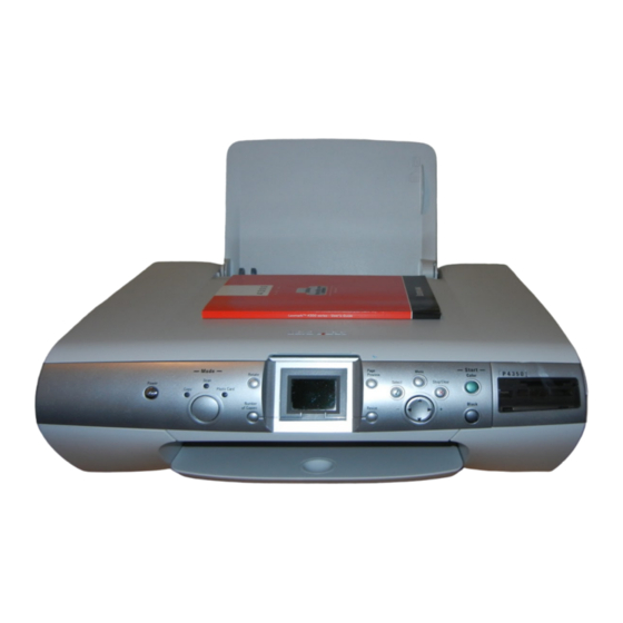
Page 13: Control Panel
4421-XXX Control panel Buttons Functions Power This button turns the All-In-One on and off. Rotate This button rotates the image on the control panel display 90 degrees for easier viewing of photos. Page Preview This button allows you to preview an image before it is printed, scanned, or copied. - Page 14 4421-XXX Buttons Functions Cancel • This button cancels a copy, scan, or print job. • In Photo Card mode, this button deselects the preview photo selected. Other helpful information about this button: • When viewing a photo, you can cancel all photo selections.
- Page 15 4421-XXX Buttons Functions Up Arrow • This button allows you to scroll through menu options. • This button changes the selected area when cropping an image. • In Photo Card mode, this button allows you to skip forward through the memory card to view every tenth picture on the control panel display.
-
Page 16: Navigating The Control Panel Menus
4421-XXX Buttons Functions Number of In Copy and Photo Card modes: Copies – This button specifies the number of copies to print. In Scan mode: – This button does not function. Mode This button selects Copy, Scan, or Photo Card mode. Navigating the control panel menus 1. -
Page 17: Acronyms
4421-XXX Acronyms Automatic Document Feeder Automatic Sheet Feeder Bill of Material Charge Coupled Device Contact Image Sensor DBCS Double Byte Character Set Direct Print Service End of Form Electrostatic Discharge Flexible Flat Cable Flat Printhead Cable Field Replaceable Unit HVPS High Voltage Power Supply Liquid Crystal Display Light-Emitting Diode... - Page 18 4421-XXX Service Manual...
-
Page 19: Diagnostic Information
Press the Power button to turn the All-In-One on. 1. The Power and Copy lights come on. 2. Lexmark 4300 Series appears on the LCD. 3. The Copy, Scan, and Photo Card lights go through a flashing sequence, and then the Copy light stays on. -
Page 20: Error Codes
4421-XXX Error codes Catastrophic errors In this state, the All-In-One is in an error mode such that operation cannot continue. These errors affect the entire All-In-One. The LCD is on and operating. An error message is displayed on the LCD. The All-In-One accepts data, but discards it and does not respond. - Page 21 4421-XXX Code Name Description Action 0002 Hardware General hardware Unplug the All-In-One; Failure failure (unable to wait a few seconds, localize failure to a then plug the specific system) All-In-One back in and turn the power on. If the error remains, clean the NVRAM by pressing the Up Arrow and Menu...
-
Page 22: Non-Catastrophic Errors
4421-XXX Non-catastrophic errors In this state, an error has occurred, but the All-In-One can continue to operate. You may need to intervene using a button press, or the machine may time out and return to the Error! Reference source not found state, depending upon the error. - Page 23 4421-XXX Code Name Description Action 1202 Data Error Incorrect data has Unplug the All-In-One; been sent from the wait a few seconds, host computer to the then plug the printer. All-In-One back in and turn the power on. If the error remains, replace USB cable.
-
Page 24: Post Symptom Table
4421-XXX Code Name Description Action 2200 Scan Carrier The scan carrier has Unplug the All-In-One; Stall stalled. wait a few seconds, then plug the All-In-One back in and turn the power on. If the error remains, check all connections to the scanner. If connections are okay and error continues, replace the system... -
Page 25: Symptom Tables
4421-XXX Symptom tables Locate the symptom in the following tables and take the appropriate action. Carrier transport problems Symptom Action • No carrier movement Go to the “Carrier transport service check” on page 2-10. • Slow carrier movement • Carrier stops. •... -
Page 26: Printer Communication Problems
4421-XXX Printer communication problems Symptom Action Not able to print Test Page Check the USB cable and system board cable connections. If connections are okay, replace the system board. Go to “System board removal” on page 4-16. Scanner problems Symptom Action •... -
Page 27: Power Problems
4421-XXX Power problems Symptom Action There is no power in the Go to the “Power service check” All-In-One; motors do not operate. on page 2-14. Print quality problems Symptom Action • Voids in characters Go to the “Print quality service check”... -
Page 28: Service Checks
4421-XXX Service checks Carrier transport service check Action • System Board Check the carrier transport motor connector J18 on the system board. If it is connected, check for • Carrier approximately 30 V dc on pins 1 and 2 or at the wire Transport connections located on the rear of the carrier transport Motor... -
Page 29: Cis Module Assembly Service Check
4421-XXX Action Carrier Assembly Check the following parts for wear or damage: • Printhead cartridge latch • Latch spring • Carrier • Printhead cables Reseat the printhead cables in the system board. If any of these parts are defective, replace the carrier assembly. -
Page 30: Maintenance Station Service Check
4421-XXX Maintenance station service check The maintenance station has three functions: 1. Wipes (cleans) the printhead nozzle plates 2. Provides a place for printheads to fire all nozzles, keeping them clean for printing 3. Seals the printheads when they are not being used to prevent the nozzles from drying Action Maintenance... -
Page 31: Paper Feed Service Check
4421-XXX Paper feed service check If the All-In-One does not have paper jam problems, continue with this service check. If the All-In-One has paper jam problems, examine the printer for the following before you begin the service check: • Check the entire paper path for obstructions. •... -
Page 32: Power Service Check
4421-XXX Action Midframe Check the following for wear: Assembly • Small feed rollers • Large feed roller • Exit roller • Star rollers If any of the rollers are worn and causing a paper feed problem, replace the print engine. Go to “Print engine removal”... -
Page 33: Print Quality Service Check
To clean the nozzles using the computer: 1. Load plain paper. 2. Open the Lexmark Solution Center. 3. From the Maintenance tab, click Clean to fix horizontal streaks. 4. Click Print. A nozzle page prints, forcing ink through the nozzles to clean the clogged nozzles. - Page 34 4421-XXX FRU/Problem Action Color print Be sure the print cartridge nozzle plate is clean. Clean cartridge cross with a soft cloth. contamination If cross contamination occurs, check for: • Maintenance station wiper damage • Used tape on the printhead nozzle plate If the wiper is damaged, replace the maintenance station.
-
Page 35: Scan And Copy Quality Service Check
(jagged or rough) can be adjusted by performing the printhead alignment. To align the print cartridges: 1. Load plain paper. 2. Open the Lexmark Solution Center. 3. From the Maintenance tab, click Align to fix blurry edges. 4. Click Print to print an alignment page and to automatically align the cartridges. - Page 36 4421-XXX FRU / Problem Action Blank Copies If blank copies are found, make sure the original document is facing down on the scanner bed. Check the print cartridges to see if they need to be cleaned or replaced. Check the Copy Quality settings. 1.
-
Page 37: Diagnostic Aids
4421-XXX 3. Diagnostic aids Self Test mode To enter the Self Test mode, press the Up Arrow and Menu button simultaneously. The LCD displays the Self Test menu screen when the Self Test mode is enabled. Note: Press Cancel on any message screen to return to the Self Test menu. - Page 38 4421-XXX 9. Media Sensor Test—The media sensor reads the current paper type. A message displays the type of paper. If no paper is detected, None appears on the LCD. 10. Last USB Connect Speed—Shows the status and connection speed of the USB connection.
-
Page 39: Repair Information
4421-XXX 4. Repair information This chapter explains how to make adjustments to the All-In-One and how to remove defective parts. Warning: Read the following before handling electronic parts. Handling ESD-sensitive parts Many electronic products use parts that are known to be sensitive to electrostatic discharge (ESD). -
Page 40: Adjustments
4421-XXX Adjustments The user is directed in the Lexmark Solution Center to perform the printhead alignment adjustments after replacing a print cartridge. Removal procedures The following procedures are arranged according to the name of the All-In-One part discussed. CAUTION: Unplug the power cord before removing any parts. -
Page 41: Removals
4421-XXX Removals General precautions on removals Use caution when disassembling and reassembling components. The close proximity of cables to moving parts makes proper routing a must. When components are removed or replaced, any cables disturbed must be replaced as closely as possible to their original positions. Before removing any component from the machine, be sure you note the cable routing. -
Page 42: Asf Guide With Spring Removal
4421-XXX ASF guide with spring removal 1. Flex the ASF guide and remove tab (A) from the hole. 2. Remove the guide and spring. Service Manual... - Page 43 4421-XXX 3. When reinstalling, be sure the spring goes back into hole (B). Repair information...
-
Page 44: Card Reader Access Door Removal
4421-XXX Card reader access door removal 1. Press tab (A). 2. Lift and remove the door. Control panel cover removal 1. Use your fingers to loosen the control panel cover. 2. Lift and remove. Service Manual... -
Page 45: Scanner Module Assembly Removal
4421-XXX Scanner module assembly removal 1. Lift and remove the scanner lid. 2. Flex tab (A) to the left and remove the paper support. 3. Lift the scanner module assembly. Repair information... - Page 46 4421-XXX 4. Press tabs (B) on the scanner support and remove the support. 5. Press two latches (C) and lift the scanner module assembly. Service Manual...
- Page 47 4421-XXX 6. Remove three screws (D) from the midframe cover. Repair information...
- Page 48 4421-XXX 7. Use a screwdriver to release tab (E) and lift the midframe cover. 8. Unplug all cables from the system board. 9. Lift and remove the scanner module assembly. 4-10 Service Manual...
-
Page 49: Print Engine Removal
4421-XXX Print engine removal 1. Remove the scanner module assembly. 2. Remove eight screws (A). 4-11 Repair information... - Page 50 4421-XXX 3. Lift and remove the small exit roller assembly (B). 4. Press tab (C) on the small feed roller. 4-12 Service Manual...
-
Page 51: Base Assembly
4421-XXX 5. Press tabs (D) and loosen the rear cover. 6. Lift and remove the print engine. Base assembly 1. Remove the scanner module assembly. 2. Remove the rear cover. 3. Remove the print engine. The base assembly remains. 4-13 Repair information... -
Page 52: Carrier Assembly Removal
4421-XXX Carrier assembly removal 1. Remove the scanner module assembly. 2. Remove the print engine. 3. Disconnect the carrier cables from the system board. 4. Remove the carrier shaft retainer clips (A). 5. Remove the carrier shaft through the left side. 4-14 Service Manual... - Page 53 4421-XXX 6. Disconnect the encoder strip (B). 7. Press the carrier belt tensioner (C) and remove the belt (D). 8. Lift and remove the carrier assembly. 4-15 Repair information...
-
Page 54: System Board Removal
4421-XXX System board removal 1. Remove the scanner module assembly. 2. Remove the print engine. 3. Disconnect all cables. 4. Remove three screws (A). 5. Remove the system board. Warning: When removing the system board, be careful not to damage the end-of-forms flag (B). -
Page 55: Maintenance Station Removal
4421-XXX Maintenance station removal 1. Remove the scanner module assembly. 2. Remove the print engine. 3. Press three clips (A). 4-17 Repair information... - Page 56 4421-XXX 4. Slide the maintenance station forward and down to remove. 4-18 Service Manual...
-
Page 57: Rear Cover Removal
4421-XXX Rear cover removal 1. Remove the scanner module assembly. 2. Press four clips (A). 3. Remove the rear cover. 4-19 Repair information... - Page 58 4421-XXX 4-20 Service Manual...
-
Page 59: Locations And Connectors
4421-XXX 5. Locations and connectors System board Connector Connectors Description Approximate voltage (total number of pins) Media Sensor Carrier — Card Reader Pin 2 9 V dc Carrier Carrier Card Reader Control Panel Card Reader Paper Feed Encoder Dial — Scanner Motor Pins 1,2,3,4 1 V dc... - Page 60 4421-XXX Service Manual...
-
Page 61: Preventive Maintenance
4421-XXX 6. Preventive maintenance This chapter contains lubrication specifications. Follow these recommendations to prevent problems and maintain optimum performance. Lubrication specifications Lubricate only when parts are replaced or as needed, not on a scheduled basis. Use grease P/N 99A0394 to lubricate the following: •... - Page 62 4421-XXX Service Manual...
-
Page 63: Parts Catalog
4421-XXX 7. Parts catalog How to use this parts catalog The following legend is used in the parts catalog: Asm- Part Units/ Units/ Description Index number mach • Asm-index: Identifies the assembly and the item in the diagram. For example, 3-1 indicates assembly 3 and item number 1. •... -
Page 64: Assembly 1: Covers, Scanner, And Base
4421-XXX Assembly 1: Covers, scanner, and base Service Manual... - Page 65 4421-XXX Assembly 1: Covers, scanner, and base Asm- Part Units/ Units/ Description Index number mach 56P2612 Support, paper (001, 002) 56P2772 Guide, ASF with spring (001, 002) 56P3901 Module, scanner assembly (001, 002) 56P3902 Cover, rear (001, 002) 56P2614 Support, scanner (001, 002) 56P2615 Base, printer assembly (001, 002) 56P2796...
- Page 66 4421-XXX Assembly 1 (cont.): Covers, scanner, and base Service Manual...
- Page 67 4421-XXX Covers, scanner, and base Assembly 1 (cont.): Asm- Part Units/ Units/ Description Index number mach 56P3915 Cover, control panel Traditional Chinese (001, 002) 56P3916 Cover, control panel Russian (001, 002) 56P3917 Badge, P4350 model number (001) 56P3918 Badge, P4330 model number (002) 7373897 Plain package B/M includes: carton, cushion set, and sealing tape USA/...
-
Page 68: Assembly 2: Engine, Carrier, And Electronics
4421-XXX Assembly 2: Engine, carrier, and electronics Service Manual... -
Page 69: Index
4421-XXX Assembly 2: Engine, carrier, and electronics Asm- Part Units/ Units/ Description Index number mach 56P3900 Board, system 4350 (001) 56P3919 Board, system 4330 (002) 21G0175 Engine, print assembly (001, 002) 13D0400 Supply, power (LV) 120 V (001, 002) 56P2611 Carrier, assembly with cables and belt (001, 002) 56P2617... - Page 70 4421-XXX Service Manual...
- Page 71 4421-XXX Index ESD-sensitive parts abbreviations acronyms handling ESD-sensitive parts adjustments 2-17 lubrication specifications buttons Black Start Cancel maintenance station problems Color Start menus, control panel Down Arrow Left Arrow (-) Menu Mode paper feed 2-16 Number of Copies paper feed motor 2-13 Page Review paper feed problems...
- Page 72 4421-XXX system board 4-16 safety information scanner problems scanner specifications Self Test mode service checks carrier transport 2-10 CIS module assembly 2-11 maintenance station 2-12 paper feed 2-13 power 2-14 print quality 2-15 scan/copy quality 2-17 start symptom tables carrier transport problems control panel problems maintenance station problems paper feed problems...
-
Page 73: Part Number Index
4421-XXX Part number index Description Page 11B5621 Cord, power UK/Ireland/Hong Kong (001, 002) ... . . 11B5622 Cord, power Chile/Europe/Asia (001, 002) ....11B5624 Cord, power Australia (001, 002) . - Page 74 4421-XXX 56P3918 Badge, P4330 model number (002) ..... . 56P3919 Board, system 4330 (002) ......7373897 Plain package B/M USA/Canada/LAD (001, 002) .
Need help?
Do you have a question about the 4300 Series and is the answer not in the manual?
Questions and answers