Thermablaster WDFT060-VF-IR User Manual
Vent-free gas wall heater
Hide thumbs
Also See for WDFT060-VF-IR:
- Owner's manual (34 pages) ,
- Operational instructions (2 pages)
Table of Contents
Advertisement
WARNING:
This appliance is equipped for
(Natural and/or Propane) gas. Field
conversion is not permitted other than
between natural or propane gases in dual
fuel models only.
CAUTION - FOR YOUR SAFETY
INSTALLER: Leave this manual with the appliance
CONSUMER: Retain this manual for future reference
This is an unvented gas-fired heater. It uses air (oxygen) from the room in
which it is installed. Provisions for adequate combustion and ventilation
air must be provided. Refer to Air For Combustion and Ventilation
section on page
This appliance may be installed in an aftermarket, permanently located,
manufactured (mobile) home, where not prohibited by local codes.
This appliance is only for use with propane or natural gas.
This appliance is equipped with a simple means to switch between
propane and natural gas in dual fuel models only. Field conversion by
any other means including the use of a kit is not permitted.
8
of this manual.
Warranty is void if not professionally installed.
Conforms to ANSI Z21.11-2b-2013. Gas-Fired Room Heater Volume II, Unvented Room Heater
Vent-Free Gas Wall Heater
MODEL:
WDFT060/100/250-VF-IR (DUAL FUEL)
WNT060/100/250-VF-IR (NATURAL GAS)
WLT060/100/250-VF-IR (PROPANE GAS)
1
Reecon North America
1090 Freeport Road
nd
2
Floor
Pittsburgh, PA 15238
Advertisement
Table of Contents

Related Manuals for Thermablaster WDFT060-VF-IR


Summary of Contents for Thermablaster WDFT060-VF-IR
- Page 1 WARNING: This appliance is equipped for Vent-Free Gas Wall Heater (Natural and/or Propane) gas. Field conversion is not permitted other than MODEL: WDFT060/100/250-VF-IR (DUAL FUEL) between natural or propane gases in dual WNT060/100/250-VF-IR (NATURAL GAS) fuel models only. WLT060/100/250-VF-IR (PROPANE GAS) CAUTION - FOR YOUR SAFETY INSTALLER: Leave this manual with the appliance CONSUMER: Retain this manual for future reference...
-
Page 2: Product Specifications
PRODUCT SPECIFICATIONS Model WDFT060-VF-IR WDFT100-VF-IR WDFT250-VF-IR 6000 10000 25000 BTU(available) Gas type Using natural gas Using natural gas Using natural gas Press regulator setting 4 in w.c. 4 in w.c. 4 in w.c. Inlet gas pressure (inches of water) for purpose of input adjustment Maximum 7 in w.c. - Page 3 Model WNT060-VF-IR WNT100-VF-IR WNT250-VF-IR 6000 10000 25000 BTU(available) Gas type natural gas natural gas natural gas Press regulator setting 4 in w.c. 4 in w.c. 4 in w.c. Inlet gas pressure (inches of water) for purpose of input adjustment Maximum 7 in w.c.
-
Page 4: Important Safety Information
1. IMPORTANT SAFETY INFORMATION IMPORTANT: Read this owner’s manual carefully and completely before trying to assemble, operate, or service this heater. Improper use of this heater can cause serious injury or death from burns, fire, explosion, electrical shock, and carbon monoxide poisoning. Only a qualified installer, service agent, or local gas supplier may install and service this product. -
Page 5: Qualified Installing Agency
CAUTION: Two gas line installations at the same time are prohibited. The access plate to the simple switching means on the dual fuel models shall not be opened while the heater is in operation. 1. This heater shall not be installed in a room or space unless the required volume of indoor combustion air is provided by the method described in the National Fuel Gas Code, ANSI Z223.1/NFPA 54, the International Fuel Gas Code, or applicable local codes. -
Page 6: Product Features
accessories, repair and service the heater. The term “qualified agency” means any individual, firm, corporation, or company that either in person or through a representative is engaged in and is responsible for: a.) Installing, testing, or replacing gas piping or b.) Connecting, installing, testing, repairing, or servicing equipment;... -
Page 7: Water Vapor: A By-Product Of Unvented Room Heaters
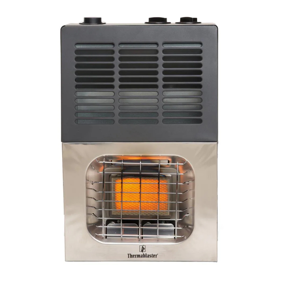
Before installing heater, make sure you have the items listed below: Igniter button Control knob Plaque plates NAT and LP gas conversion (WDFT only) Grill Figure 1 - Vent-Free Gas Heater Infrared UNPACKING 1. Remove heater from carton. 2. Remove all protective packaging applied to heater for shipping 3. -
Page 8: Determining Fresh-Air Flow For Heater Location
2. Unconfined Space 3. Confined Space The information on the followed pages will help you classify your space and provide adequate ventilation. Confined and Unconfined Space The National Fuel Gas Code, ANSI Z223 .1/NFPA 54 defines a confined space as a space whose volume is less than 50 cu. - Page 9 3. Add the BTU/hr of all fuel burning appliances in the space. Vent-free heater BTU/hr Gas water heater* BTU/hr Gas furnace BTU/hr Vented gas heater BTU/hr Gas heater logs BTU/hr Other gas appliances* + BTU/hr Total = BTU/hr Example: Gas water heater 30,000 BTU/hr Vent-free heater + 26,000 BTU/hr...
-
Page 10: Installation
Ventilation Air From lnside Building This fresh air would come from an adjoining unconfined space. When ventilating to an adjoining unconfined space, you must provide two permanent openings: one within 12 inches of the ceiling and one within 12 inches of the floor on the wall connecting the two spaces (see options 1 and 2, Figure 2). You can also remove the door into adjoining room (see option 3, Figure 2). - Page 11 CAUTION: This heater creates warm air currents. These currents move heat to wall surfaces next to heater. Installing heater next to vinyl or cloth wall coverings or operating heater where impurities (such as tobacco smoke, aromatic candles, cleaning fluids, oil or kerosene lamps, etc.) in the air exist, may cause walls to discolor.
-
Page 12: Connecting To Gas Supply
8. CONNECTING TO GAS SUPPLY WARNING: A qualified service technician must connect heater to gas supply. Follow all local codes. WARNING: This appliance requires a 3/8-inch NPT (National Pipe Thread) inlet connection to the pressure regulator. WARNING: Never connect heater to private (non-utility) gas wells. This gas is commonly known as wellhead gas. - Page 13 CAUTION: Two gas li nes installa ation at the same time is forbidde en. Do not t he open co over while th he heater is ru unning. Heate er is pre-set t at factory for propane e gas; no c changes are requir red for conn...
- Page 14 After gas s conversio on, make su ure to repla knob loc ck and the s screw. Reverse s steps 1 thro ough 7 to co onvert back k to LP gas s if needed. For chang ing from na atural gas supply to propane su...
-
Page 15: Checking Gas Connections
CHECKING GAS CONNECTIONS WARNING: Test all gas piping and connections for leaks after installing or servicing. Correct all leaks at once. WARNING: Never use an open flame to check for a leak. Apply a mixture of liquid soap and water to all joints. -
Page 16: Operation
9. OPERATION FOR YOUR SAFETY READ BEFORE LIGHTING WARNING: If you do not follow these instructions exactly, a fire or explosion may result causing property damage, personal injury or loss of life. 1) When lighting the pilot, follow these instructions exactly. 2) BEFORE LIGHTING, smell all around the appliance area for gas. - Page 17 Lighting INSTRUCTIONS Before Lighting 1. Make sure the heater is properly installed and connected. Open the external safety shut off valve (not part of the heater) on gas inlet line to the heater. 2. Wait five (5) minutes to clear out air inside gas lines. Smell if there is any leakage. IMPORTANT: If you smell any gas, don’t try to light any appliances, do not touch electrical switches or use any phone in the building.
-
Page 18: Inspecting Burner
Heater Models: WDFT250-VF-IR WNT250-VF-IR WLT250-VF-IR Igniter button Temperature/Pilot Control button Figure11 1. Turn the appliance combination control valve button to the “Pilot” position. 2. Push down the appliance combination control valve button and keep it depressed for several seconds, so that all the air in the manifolds are clear. 3. -
Page 19: Care And Maintenance
10. CARE AND MAINTENANCE WARNING: Turn off heater and let cool before servicing CAUTION: You must keep control areas, burner, and circulating air passageways of the heater clean. Inspect these areas of heater before each use. Have heater inspected yearly by a qualified service technician. -
Page 20: Troubleshooting
11. TROUBLE SHOOTING WARNING: If you smell gas: 1) Open the window and door immediately. 2) Shut off gas supply. 3) Do not try to light any appliance. 4) Do not touch any electrical switch; do not use any phone in your building. 5) Immediately call your gas supplier from a neighbor’s phone. - Page 21 Burner backfiring 1. Burner orifice is clogged or 1. Clean burner orifice (see Care and during combustion. damaged. Maintenance, page 15) or replace. 2. Burner is damaged. 2. Contact customer service. 3. Gas regulator is defective. 3. Replace gas regulator. Yellow flame during 1.
- Page 22 ILLU USTRATE E D PARTS S (Models s : WDFT0 060-VF-IR R)
- Page 23 PARTS LIST (Model: WDFT060-VF-IR) Code Description Code Description Grill NG Nozzle Body cover LPG Nozzle Scatter panel Nozzle holder Gas elbow Gas allocator Appliance regulator connecter 2 26 Ceramic plaque Appliance regulator bracket LPG ODS Appliance regulator NG ODS Appliance regulator connecter 1 29...
- Page 24 ILLU USTRATE E D PARTS S (Model: : WDFT10 00-VF-IR) )
- Page 25 PARTS LIST (Model: WDFT100-VF-IR) Code Description Code Description Grill Nozzle holder Body cover NG Nozzle Scatter panel LPG Nozzle Gas elbow Nozzle holder nut Appliance regulator connecter 2 Air introducing tube Appliance regulator bracket Ceramic plaque Appliance regulator LPG ODS Appliance regulator connecter 1 NG ODS Shell...
- Page 26 ILLU USTRATE E D PARTS S (Model: : WDFT25 50-VF-IR) )
- Page 27 PARTS LIST (Model: WDFT250-VF-IR) Code Description Code Description Grill LPG ODS Body cover NG ODS Scatter panel Right insulation board Shell Combination control valve seat Rear insulation board Gas Valve bracket Left insulation board Combination control valve Over-heat cut-off Gas Connecter Rear cover Gas pipe nut Installation bracket...
- Page 28 ILLU USTRATE E D PARTS S (Models s : WNT06 60-VF-IR/W W LT060- - VF-IR)
- Page 29 Part List (Models: WNT060-VF-IR/WLT060-VF-IR) Code Description Code Description Grill Nozzle holder bracket Body cover LP Nozzle (WLT060-VF-IR) Scatter panel NG Nozzle (WNT060-VF-IR) Gas elbow Nozzle holder Appliance regulator connecter 2 Gas allocator Appliance regulator bracket Ceramic plaque NG Appliance regulator NG ODS (WNT060-VF-IR) (WNT060-VF-IR) LP Appliance regulator...
- Page 30 ILLU USTRATE E D PARTS S (Models s : WNT10 00-VF-IR/W W LT100- - VF-IR)
- Page 31 Part List (Models: WNT100-VF-IR/WLT100-VF-IR) Code Description Code Description Grill Nozzle holder bracket Body cover Nozzle holder Scatter panel LP Nozzle (WLT100-VF-IR) Gas elbow NG Nozzle (WNT100-VF-IR) Appliance regulator connecter 2 Nozzle holder fixing nut Appliance regulator bracket Air introducing tube NG Appliance regulator Ceramic plaque (WNT100-VF-IR)
- Page 32 ILLU USTRATE E D PARTS S (Models s : WNT25 50-VF-IR/W W LT250- - VF-IR)
- Page 33 Part List (Models: WNT250-VF-IR/WLT250-VF-IR) Code Description Code Description Grill Ceramic plaque Body Cover NG ODS (WNT260-VF-IR) Scatter panel LP ODS (WLT260-VF-IR) Shell Right insulation board Rear insulation board Combination control valve seat Left insulation board Valve bracket Rear cover Combination control valve Installation bracket Connecter Fixing racket...
- Page 34 Annual Service Schedule Service Performed Service Date Please send in the form below to our office listed below or register online at www.thermablaster.com Reecon North America Attn: Thermablaster 1090 Freeport Road Floor Pittsburgh, PA 15238 ------------------------------------------------------------------------------------------------------------------------------- Contact Information Product Information...
Need help?
Do you have a question about the WDFT060-VF-IR and is the answer not in the manual?
Questions and answers