Table of Contents
Advertisement
Quick Links
WARNING: This appliance is equipped for
(Natural and/or Propane) gas. Field
conversion is not permitted other than
between natural or propane gases in dual
fuel models only.
CAUTION - FOR YOUR SAFETY
INSTALLER: Leave this manual with the appliance
CONSUMER: Retain this manual for future reference
This is an unvented gas-fired heater. It uses air (oxygen) from the room in
which it is installed. Provisions for adequate combustion and ventilation
air must be provided. Refer to Air For Combustion and Ventilation
section on page 8 of this manual.
This appliance may be installed in an aftermarket, permanently located,
manufactured (mobile) home, where not prohibited by local codes.
This appliance is only for use with propane or natural gas.
This appliance is equipped with a simple means to switch between
propane and natural gas in dual fuel models only. Field conversion by
any other means including the use of a kit is not permitted.
Warranty is void if not professionally installed.
Conforms to ANS Z21.11-2-2013. Gas-Fired Room Heater Volume II, Unvented Room Heater
- 1 -
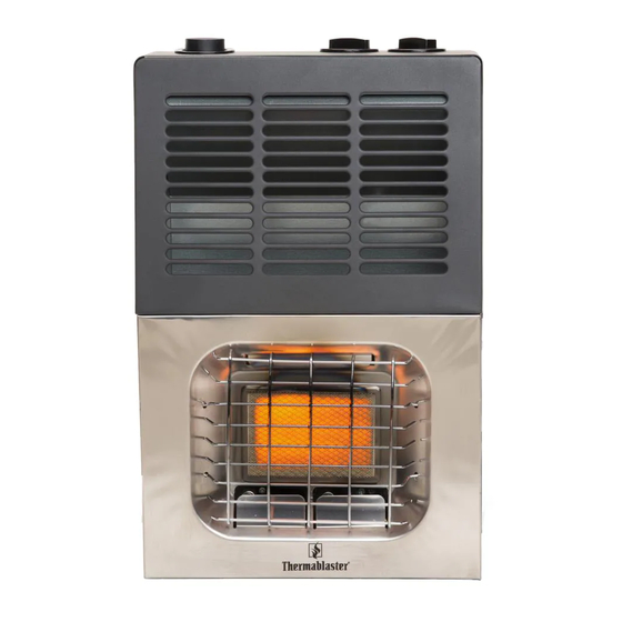
Vent-Free Gas Wall Heater
MODEL: WDFT060/100/250-VF-IR (DUAL FUEL)
WNT060/100/250-VF-IR (NATURAL GAS)
WLT060/100/250-VF-IR (PROPANE GAS)
Reecon North America
1090 Freeport Road
nd
2
Floor
Pittsburgh, PA 15238
Advertisement
Table of Contents

Related Manuals for Thermablaster WDFT060-VF-IR


Summary of Contents for Thermablaster WDFT060-VF-IR
- Page 1 WARNING: This appliance is equipped for Vent-Free Gas Wall Heater (Natural and/or Propane) gas. Field conversion is not permitted other than MODEL: WDFT060/100/250-VF-IR (DUAL FUEL) between natural or propane gases in dual WNT060/100/250-VF-IR (NATURAL GAS) fuel models only. WLT060/100/250-VF-IR (PROPANE GAS) CAUTION - FOR YOUR SAFETY INSTALLER: Leave this manual with the appliance CONSUMER: Retain this manual for future reference...
-
Page 2: Product Specifications
PRODUCT SPECIFICATIONS 1)For Dual Fuel Model WDFT060-VF-IR WDFT100-VF-IR WDFT250-VF-IR Input Rating (Btu/hr) 6000 10000 25000 Gas type Using natural gas Using natural gas Using natural gas Manifold Pressure (W.C.) 5.2” 5.2” 5.2” Nominal Input Pressure (W.C.) 7” 7” 7” Gas type... - Page 3 3) For Propane Gas Model WLT060-VF-IR WLT100-VF-IR WLT250-VF-IR Input Rating (Btu/hr) 6000 10000 25000 Gas type Manifold Pressure (W.C.) 10” 10” 10” Nominal Inlet pressure (W.C.) 11” 11” 11” Ignition Electric Pulse Electric Pulse Electric Pulse Package Dimension inches 15.7×7.5×25.6 18.1×7.5×28.7 30.25”×11.00”×28.75”...
-
Page 4: Important Safety Information
1. IMPORTANT SAFETY INFORMATION IMPORTANT: Read this owner’s manual carefully and completely before trying to assemble, operate, or service this heater. Improper use of this heater can cause serious injury or death from burns, fire, explosion, electrical shock, and carbon monoxide poisoning. Only a qualified installer, service agent, or local gas supplier may install and service this product. - Page 5 WARNING: Failure to position the parts in accordance with these diagrams or failure use only parts specifically approved with this heater may result in property damage or personal injury. CAUTION: Two gas line installations at the same time are prohibited. The ignition button on the dual fuel models shall not be depressed while the heater is in operation.
-
Page 6: Product Features
QUALIFIED INSTALLING AGENCY Only a qualified agency should install and replace gas piping, gas utilization equipment or accessories, repair and service the heater. The term “qualified agency” means any individual, firm, corporation, or company that either in person or through a representative is engaged in and is responsible for: a.) Installing, testing, or replacing gas piping or b.) Connecting, installing, testing, repairing, or servicing equipment;... - Page 7 3. Preparing for installation Before beginning assembly or operation of the product, make sure all parts are present. Compare parts with package contents list and diagram above. If any part is missing or damaged, do not attempt to assemble, install or operate the product. Contact customer service for replacement parts. Before installing heater, make sure you have the items listed below: Igniter knob Thermostat knob...
-
Page 8: Water Vapor: A By-Product Of Unvented Room Heaters
4. WATER VAPOR: A BY-PRODUCT OF UNVENTED ROOM HEATERS Water vapor is a by-product of gas combustion. An unvented room heater produces approximately one (1) ounce (30 ml) of water for every 1,000 BTUs (0.3 KWs) of gas input per hour. Unvented room heaters are recommended as supplemental heat (a room) rather than a primary heat source (an entire house). -
Page 9: Determining Fresh-Air Flow For Heater Location
Unusually Tight Construction The air that leaks around doors and windows may provide enough fresh air for combustion and ventilation. However, in buildings of unusually tight construction, you must provide additional fresh air. Unusually tight construction is defined as construction where: a) Walls and ceilings exposed to the outside atmosphere have a continuous water vapor retarder with a rating of one perm (6×10-11kg per pa-sec-m ) or less with openings gasket or sealed and... - Page 10 4. Compare the maximum BTU/hr the space can support with the actual amount of BTU/hr used BTU/hr (maximum the space can support) BTU/hr (actual amount of BTU/hr used) Example: 51,200 BTU/hr (maximum the space can support) 56,000 BTU/hr (actual amount of BTU/hr used) The space in the above example is a confined space because the actual BTU/hr used is more than the maximum BTU/hr the space can support.
-
Page 11: Installation
Ventilation Air From Outdoors Provide extra fresh air by using ventilation grills or ducts. You must provide two permanent openings: one within 12 inches of the ceiling and one within 12 inches of the floor. Connect these items directly to the outdoors or spaces open to the outdoors. -
Page 12: Locating Heater
Check Gas Type Be sure your gas supply is right for your heater. Otherwise, call dealer where you bought the heater from for proper type heater. Clearances to Combustibles Carefully follow the instructions below. This heater is a freestanding unit designed to be mounted on a wall. -
Page 13: Natural Gas Models
NATURAL GAS MODELS: CAUTION: Check your gas line pressure before connecting heater to gas line. Gas line pressure must be no greater than 8 inches of water column. If gas line pressure is higher, damage on appliance regulator could occur. External regulator PROPANE MODELS: CAUTION: Never connect heater directly to the gas supply. - Page 14 Pressure Testing Gas Supply Piping System Test Pressures In Excess Of 1/2 PSIG (3.5kPa) 1. Disconnect heater with its appliance main gas valve (control valve) and equipment shutoff valve from gas supply piping system. Pressures in excess of 1/2 PSIG will damage heater regulator. 2.
-
Page 15: Operation
9. OPERATION FOR YOUR SAFETY READ BEFORE LIGHTING WARNING: If you do not follow these instructions exactly, a fire or explosion may result causing property damage, personal injury or loss of life. 1) When lighting the pilot, follow these instructions exactly. 2) BEFORE LIGHTING, smell all around the appliance area for gas. - Page 16 Heater Models: WDFT060/100-VF-IR WNT060/100-VF-IR WLT060/100-VF-IR Igniter button Gas valve button Temperature control button Figure - 9 1. Turn the thermostat Control button to full position, turn the appliance gas valve ( -PILOT-OFF) button to the “Pilot” position. 2. Push down the appliance gas valve and keep it depressed for several minutes, so that all the air in the manifests are cleared out.
-
Page 17: Inspecting Burner
1. Turn the appliance combination control valve button to the “Pilot” position. This should line up with arrow on the top of the heater. 2. Push down the appliance combination control valve button and keep it depressed for several minutes, so that all the air in the manifests are cleared out. -
Page 18: Care And Maintenance
10. CARE AND MAINTENANCE WARNING: Turn off heater and let cool before servicing CAUTION: You must keep control areas, burner, and circulating air passageways of the heater clean. Inspect these areas of heater before each use. Have heater inspected yearly by a qualified service technician. -
Page 19: Troubleshooting
11. TROUBLE SHOOTING WARNING: If you smell gas: 1) Open the window and door immediately. 2) Shut off gas supply. 3) Do not try to light any appliance. 4) Do not touch any electrical switch; do not use any phone in your building. 5) Immediately call your gas supplier from a neighbor’s phone. - Page 20 Burner backfiring during 1. Burner orifice is clogged, 1. Clean burner or replace burner orifice, combustion. 2. Burner is damaged. 2. Contact customer service. 3. Burner is not correctly aligned 3. Contact customer service. 4. Gas regulator or/and appliance 4. Contact customer service. regulator are defective.
- Page 21 ILLUSTRATED PARTS (Models: WDFT060-VF-IR) - 21 -...
- Page 22 PARTS LIST (Model: WDFT060-VF-IR) Code Description Code Description Grill Nozzle holder Body cover NAT supplemental nozzle Scatter panel LP nozzle Appliance regulator connecter 2 26 Nozzle seat Appliance regulator bracket Ceramic plaque Appliance regulator LPG ODS Appliance regulator connecter 1 29...
- Page 23 ILLUSTRATED PARTS (Model: WDFT100-VF-IR) - 23 -...
- Page 24 PARTS LIST (Model: WDFT100-VF-IR) Code Description Code Description Grill Nozzle seat Body cover NAT supplemental nozzle Scatter panel LP nozzle Appliance regulator connecter 2 Nozzle seat nut Appliance regulator Air introducing tube Appliance regulator bracket Ceramic plaque Appliance regulator connecter 1 NG ODS Shell LPG ODS...
- Page 25 ILLUSTRATED PARTS (Model: WDFT250-VF-IR) - 25 -...
- Page 26 PARTS LIST (Model: WDFT250-VF-IR) Code Description Code Description Grill Burner fixing racket 1 Body cover Burner fixing racket 2 Scatter panel NAT ODS Shell Right insulation board Rear insulation board LP ODS Left insulation board Control valve seat Pulse igniter Control valve bracket Battery pack Combination gas control valve...
- Page 27 ILLUSTRATED PARTS (Models: WNT060-VF-IR/WLT060-VF-IR) - 27 -...
- Page 28 Part List (Models: WNT060-VF-IR/WLT060-VF-IR) Code Description Code Description Grill Nozzle seat nut Body cover Nozzle holder Scatter panel LP nozzle Appliance regulator connecter 2 24 NAT supplemental nozzle Appliance regulator bracket Nozzle seat Appliance regulator Ceramic plaque Appliance regulator connecter 1 27 LPG ODS Gas distribution valve assembly NG ODS...
- Page 29 ILLUSTRATED PARTS (Models: WNT100-VF-IR/WLT100-VF-IR) - 29 -...
- Page 30 Part List (Models: WNT100-VF-IR/WLT100-VF-IR) Code Description Code Description Grill Nozzle seat Body cover NAT supplemental nozzle Scatter panel LP nozzle Appliance regulator connecter 2 Nozzle seat nut Appliance regulator Air introducing tube Appliance regulator bracket Ceramic plaque Appliance regulator connecter 1 NG ODS Shell LPG ODS...
- Page 31 ILLUSTRATED PARTS (Models: WNT250-VF-IR/WLT250-VF-IR) - 31 -...
- Page 32 Part List (Models: WNT250-VF-IR/WLT250-VF-IR) Code Description Code Description Grill Burner fixing racket 2 Body cover LP ODS Scatter panel NAT ODS Shell Right insulation board Rear insulation board Control valve seat Left insulation board Control valve bracket Pulse igniter Combination gas control valve Battery pack Connecter Bottom cover...
- Page 33 If you have additional support questions please call our customer service at 1-877-670-8428 or visit www.thermablaster.com Annual Service Schedule Service Performed Service Date Please send in the form below to our office listed below or register online at www.thermablaster.com Reecon North America Attn: Thermablaster 1090 Freeport Road Floor...
Need help?
Do you have a question about the WDFT060-VF-IR and is the answer not in the manual?
Questions and answers